CN215980646U - Elastic eccentric speed reducer - Google Patents
Elastic eccentric speed reducer Download PDFInfo
- Publication number
- CN215980646U CN215980646U CN202122198688.7U CN202122198688U CN215980646U CN 215980646 U CN215980646 U CN 215980646U CN 202122198688 U CN202122198688 U CN 202122198688U CN 215980646 U CN215980646 U CN 215980646U
- Authority
- CN
- China
- Prior art keywords
- elastic
- eccentric
- sleeve
- planet carrier
- transmission
- Prior art date
- Legal status (The legal status is an assumption and is not a legal conclusion. Google has not performed a legal analysis and makes no representation as to the accuracy of the status listed.)
- Active
Links
Images


Landscapes
- Retarders (AREA)
Abstract
The utility model discloses an elastic eccentric speed reducer, which comprises an elastic eccentric sleeve fixedly arranged on an input shaft of the speed reducer, wherein the periphery of the elastic eccentric sleeve is provided with at least two eccentric mounting positions with different phase angles, each eccentric mounting position is respectively provided with a transmission bearing, the periphery of each transmission bearing is respectively provided with a transmission gear, the periphery of each transmission gear is meshed with a fixedly arranged fixed gear ring, and the elastic eccentric sleeve is provided with an elastic adjustment increment which enables the transmission gear to be fully meshed with the fixed gear ring; the elastic eccentric sleeve has elastic deformation, and the elastic adjustment increment enables the transmission gear and the meshing teeth of the fixed gear ring to be in a sufficient meshing relationship, so that the fixed gear ring and the transmission gear are always in a close fit relationship, errors existing in assembly in the prior art are compensated and eliminated, and a gear side gap does not exist between the transmission gear and the fixed gear ring when the transmission gear rotates reversely.
Description
Technical Field
The utility model relates to the technical field of speed reducers, in particular to an elastic eccentric speed reducer.
Background
With the rapid development of industrial automation technology, robots are increasingly gaining attention as important industrial automation equipment, and the application of robots is increasingly widespread. The robot technology mainly concentrates the latest research results of various technologies such as mechanical engineering, automatic control, artificial intelligence and the like, embodies the latest achievement of photoelectric integration, and is one of the fields with the most active scientific and technical development in the present day. The mechanical arm is an automatic mechanical device which is widely applied in the technical field of robots at present, plays an extremely important role in production and life, and in practical application, a plurality of industrial process links need the mechanical arm to carry out assembling and extracting operations. The mechanical arm can receive instructions and accurately position to a certain point on a three-dimensional (or two-dimensional) space to perform operation, and the labor efficiency can be greatly improved.
The mechanical arm joint is a core component of the mechanical arm, and the overall structure, the load capacity and the sensing capacity of the joint directly influence the overall operation level of the mechanical arm. At present, a motor, a speed reducer, an encoder, a brake and a driver are commonly adopted for a common mechanical arm joint to carry out a transmission mechanism connected in series.
The speed reducer mainly adopts a special planetary speed reducer, particularly a speed reducer with small tooth difference, and has flexible structure and various application forms. The small-tooth-difference speed reducer is mostly sleeved in two or more eccentric directions by using at least two gears, and the gears are fixed through the eccentric sleeves, so that the effects of improving the speed reduction ratio and increasing the output torque are achieved. In the prior art, CN111342609A discloses an integrated speed reducer, in which a speed reducer includes an eccentric mechanism, an external gear, a gear ring and an eccentric bearing, wherein the eccentric mechanism is an eccentric sleeve having three eccentric portions, an eccentric bearing is respectively installed outside each eccentric sleeve, an external gear is respectively installed outside each eccentric bearing, the outer periphery of each external gear is in mesh transmission with the inner periphery of the gear ring, the eccentric sleeves in the prior art are made of rigid materials, and when manufacturing and design tolerances exist in the eccentric bearing, the external gear or the gear ring, there may be an error in the mesh between the external gear and the gear ring, resulting in a large transmission precision. And in order to guarantee the cooperation installation of external gear and ring gear, there is the fit clearance just when the meshing tooth of external gear and ring gear is designed, when the external gear is rotatory towards same direction all the time, contact all the time between the meshing tooth one side of external gear and the meshing tooth of ring gear, can guarantee transmission accuracy, but once the external gear is when reverse rotation, the meshing tooth opposite side of external gear need idle running a section distance just can contact the meshing tooth surface of ring gear, the distance of this idle running is called "flank clearance", the existence of this flank clearance can lead to appearing the hysteresis between input and the output, lead to corresponding slowly, influence planetary gear's precision, in order to improve the precision, it becomes the present urgent problem of solving to reduce the flank clearance.
SUMMERY OF THE UTILITY MODEL
The utility model aims to solve the technical problem of providing an elastic eccentric speed reducer which has a simple structure and a reasonable design, can effectively eliminate backlash and improve precision.
In order to solve the technical problems, the technical scheme of the utility model is as follows: elastic eccentric reduction gear, including the elastic eccentric cover of fixed mounting on the reduction gear input shaft, the periphery of elastic eccentric cover is provided with the eccentric installation position that two at least phase angles are different, each install a drive bearing respectively on the eccentric installation position, each drive bearing's periphery is installed a drive gear respectively, all drive gear's periphery meshing has a fixed gear ring of fixed mounting, be provided with on the elastic eccentric cover and make drive gear with the elastic adjustment increment of fixed gear ring full meshing.
The elastic eccentric sleeve comprises at least N elastic branch sleeve bodies, the end parts of the elastic branch sleeve bodies are in contact with each other, sleeve body fixing devices are arranged between the elastic branch sleeve bodies, the periphery of each elastic branch sleeve body is provided with an eccentric mounting position, the phase angle between every two adjacent eccentric mounting positions is 360 degrees/N, and N is larger than or equal to 2.
The sleeve body fixing device comprises fixing holes formed in the surfaces of the elastic sleeve sub bodies, and connecting pins used for fixing the elastic sleeve sub bodies are installed in the corresponding fixing holes between the elastic sleeve sub bodies.
The elastic eccentric sleeve is an integrated eccentric sleeve, two eccentric mounting positions are arranged on the periphery of the integrated eccentric sleeve, and the phase angle of the two eccentric mounting positions is 180 degrees.
The elastic eccentric sleeve is fixedly bonded with the transmission bearing.
And the elastic eccentric sleeve is fixedly bonded with the input shaft of the speed reducer.
The end face of one side of the elastic eccentric sleeve is provided with an inner bearing which is abutted against the step of the input shaft of the speed reducer, the end face of the other side of the elastic eccentric sleeve is provided with an outer bearing, the inner bearing and the outer bearing are both arranged on the input shaft of the speed reducer, and the outer bearing is also provided with a locking pressing plate which is fixedly connected with the end part of the input shaft of the speed reducer.
The planet carrier upper cover and the planet carrier lower cover are respectively and correspondingly provided with a coaxial matched planet carrier upper cover and a coaxial matched planet carrier lower cover, an anti-loosening fixing device for installing all the transmission gears is connected between the planet carrier upper cover and the planet carrier lower cover, and a torque transmission device penetrating through each transmission gear is further arranged between the planet carrier upper cover and the planet carrier lower cover.
Locking fixing device include with planet carrier upper cover, the fixed check bolt of planet carrier lower cover screw thread, check bolt by the planet carrier upper cover runs through all drive gear threaded connection is to the planet carrier lower cover, all drive gear with be provided with the position sleeve between the check bolt, the both ends of position sleeve support respectively and lean on planet carrier upper cover and planet carrier lower cover.
The torque transmission device comprises a torque transmission pin shaft, the torque transmission pin shaft penetrates through all the transmission gears, two ends of the torque transmission pin shaft are respectively positioned on the upper cover and the lower cover of the planet carrier, and a pin shaft sleeve is respectively arranged between each transmission gear and the torque transmission pin shaft.
According to the technical scheme, the elastic eccentric speed reducer comprises an elastic eccentric sleeve fixedly mounted on an input shaft of the speed reducer, at least two eccentric mounting positions with different phase angles are arranged on the periphery of the elastic eccentric sleeve, a transmission bearing is mounted on each eccentric mounting position, a transmission gear is mounted on the periphery of each transmission bearing, a fixed gear ring fixedly mounted is meshed with the periphery of all the transmission gears, and an elastic adjustment increment for fully meshing the transmission gears and the fixed gear ring is arranged on the elastic eccentric sleeve; the utility model has the beneficial effects that: the elastic eccentric sleeve is arranged, the elastic adjustment increment which enables the transmission gear to be fully meshed with the fixed gear ring and is used for compensating the gear side clearance is arranged on the elastic eccentric sleeve, and the elastic eccentric sleeve has elastic deformation, so that the elastic adjustment increment is reserved when the elastic eccentric sleeve is arranged, and the transmission gear and the meshing teeth of the fixed gear ring are in a full meshing relationship when the elastic eccentric sleeve is installed, so that the fixed gear ring and the transmission gear are always in a close fit relationship and are used for compensating and eliminating errors existing in assembly in the prior art, the gear side clearance does not exist between the transmission gear and the fixed gear ring when the transmission gear rotates reversely, and the response frequency and the transmission precision of the joint reducer can be effectively improved; and because the elastic eccentric sleeve has elastic deformation and has a buffering effect, the impact in the gear transmission process can be effectively reduced, the service life of the gear and the bearing is prolonged, the noise is low, and the operation is stable. The elastic eccentric sleeve has the advantages of simple structure, good manufacturability and low cost, is mainly used for a high-performance and high-precision planetary gear reducer, and can effectively eliminate the tooth side clearance in gear transmission.
Drawings
The drawings are only for purposes of illustrating and explaining the present invention and are not to be construed as limiting the scope of the present invention. Wherein:
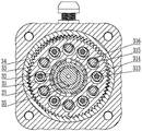
FIG. 1 is a schematic structural diagram of an embodiment of the present invention;
FIG. 2 is an enlarged schematic view at A in FIG. 1;
FIG. 3 is a schematic view of another embodiment of the present invention;
FIG. 4 is a side cross-sectional view of an embodiment of the utility model;
in the figure: 1-a joint shell; 2-a motor assembly; 21-motor output shaft; 22-a stator; 23-a rotor; 3-a retarder assembly; 31-an elastic eccentric sleeve; 32-a drive bearing; 33-a transmission gear; 34-fixed gear ring; 35-a fixing hole; 36-an inner bearing; 37-an outer bearing; 38-locking the pressure plate; 39-planet carrier upper cover; 310-inner support bearing; 311-planet carrier lower cover; 312 — an outer support bearing; 313-a lockbolt; 314-a positioning sleeve; 315-moment transmission pin; 316-pin boss; 4-encoder components.
Detailed Description
The utility model is further illustrated below with reference to the figures and examples. In the following detailed description, certain exemplary embodiments of the present invention are described by way of illustration only. Needless to say, a person skilled in the art realizes that the described embodiments can be modified in various different ways without departing from the spirit and scope of the present invention. Accordingly, the drawings and description are illustrative in nature and not intended to limit the scope of the claims.
As shown in fig. 1 and 2, the mechanical arm joint includes a joint housing 1, the joint housing 1 is used as a mounting carrier of a joint reducer, and is formed by buckling a main housing and a side end cover, and the main housing and the side end cover can be connected by threads or fixed by screws. The joint shell body 1 is internally provided with a motor component 2, a speed reducer component 3, an encoder component 4 and a driving component, and all the components are arranged in the joint shell body 1 to form an integrated joint structure.
A motor output shaft 21 is fixed at the output end of the motor component 2, the motor output shaft 21 is also a speed reducer input shaft, the motor component 2 comprises a stator 22 and a rotor 23 which are matched with each other, the outer periphery of the stator 22 of the motor component 2 is fixed in the joint shell 1 in an interference fit manner, and the inner periphery of the rotor 23 of the motor component 2 is fixed on the motor output shaft 21 in an interference fit manner; one side of the motor output shaft 21 is provided with a speed reducer assembly 3, an output end of the speed reducer assembly 3 is fixed with an output shaft, and the speed reducer assembly 3 is a speed reducer.
Referring to fig. 2, 3 and 4, the elastic eccentric reducer, includes an elastic eccentric sleeve 31 fixedly installed on an input shaft of the reducer, in this embodiment, the motor output shaft 21 is used as the input shaft of the speed reducer, the periphery of the elastic eccentric sleeve 31 is provided with at least two eccentric mounting positions with different phase angles, each eccentric mounting position is respectively provided with a transmission bearing 32, the periphery of each transmission bearing 32 is respectively provided with a transmission gear 33, the periphery of all the transmission gears 33 is engaged with a fixed gear ring 34 which is fixedly arranged, the periphery of the fixed gear ring 34 is fixedly installed in the joint housing 1, and the elastic eccentric sleeve 31 is provided with an elastic adjustment increment which enables the transmission gear 33 to be fully meshed with the fixed gear ring 34, wherein the elastic adjustment increment is represented by delta, and the elastic adjustment increment delta is equal to a theoretical center distance a-a designed center distance a between the transmission gear 33 and the fixed gear ring 34.1Design center distance a1Less than the theoretical center distance a; the theoretical center distance a between the transmission gear 33 and the fixed gear ring 34 is the difference between the radii of the fixed gear ring 34 and the transmission gear 33 after meshing, that is, the theoretical center distance a is the pitch radius r of the fixed gear ring 341Pitch circle radius r of the transmission gear 332The theoretical center distance a is designed to enable an assembly gap, namely a tooth side gap, to exist between the meshing teeth of the fixed gear ring 34 and the transmission gear 33, in order to compensate the tooth side gap, the elastic eccentric sleeve 31 is arranged, the elastic eccentric sleeve 31 is provided with an elastic adjustment increment which enables the transmission gear 33 and the fixed gear ring 34 to be fully meshed for compensating the tooth side gap, the elastic adjustment increment is reserved when the elastic eccentric sleeve 31 is designed because the elastic eccentric sleeve 31 has elastic deformation, and the transmission gear 33 and the meshing teeth of the fixed gear ring 34 are in a full meshing relationship when being installed, so that the fixed gear ring 34 and the transmission gear 33 are always in a close fit relationship for compensating and eliminating errors existing in assembly in the prior art and ensuring that the transmission gear 33 is reversely rotated,a tooth side gap does not exist between the transmission gear 33 and the fixed gear ring 34, so that the response frequency and the transmission precision of the joint speed reducer can be effectively improved; and because the elastic eccentric sleeve 31 has elastic deformation and has a buffering effect, the impact in the gear transmission process can be effectively reduced, the service life of the gear and the bearing is prolonged, the noise is low, and the operation is stable. The elastic eccentric sleeve 31 has the advantages of simple structure, good manufacturability and low cost, is mainly used for a high-performance and high-precision planetary gear reducer, and can effectively eliminate the tooth side clearance in gear transmission.
In the present embodiment, the elastic adjustment increment Δ is a floating value, which can be changed in real time according to the engagement condition between the transmission gear 33 and the fixed gear ring 34, so as to adapt to different engagement states, for example, when there is a dead point when the transmission gear 33 moves, the elastic adjustment increment Δ becomes smaller at this time, so as to facilitate the transmission gear 33 to cross the dead point.
In order to ensure the connection stability between the elastic eccentric sleeve 31 and the driving bearing 32, the elastic eccentric sleeve 31 and the driving bearing 32 are bonded and fixed.
The elastic eccentric sleeve 31 can be of an integrated structure or a split structure. When the elastic eccentric sleeve 31 is an integrated eccentric sleeve, two eccentric mounting positions are arranged on the periphery of the integrated eccentric sleeve, and the phase angle of the two eccentric mounting positions is 180 degrees, at the moment, the transmission bearings 32 can be respectively mounted on two sides of the elastic eccentric sleeve 31; when the elastic eccentric sleeve 31 is of a split structure, the elastic eccentric sleeve 31 comprises at least N elastic sub-sleeve bodies, the end parts of the elastic sub-sleeve bodies are in contact with each other, sleeve body fixing devices are arranged between the elastic sub-sleeve bodies, the periphery of each elastic sub-sleeve body is respectively provided with an eccentric mounting position, the phase angle between every two adjacent eccentric mounting positions is 360 degrees/N, N is more than or equal to 2, the number of the elastic sub-sleeve bodies is at least two, can be two, three, four or more, when two elastic sub-sleeve bodies are arranged, the two elastic sub-sleeve bodies are fixedly connected through the sleeve body fixing device, and the phase angle between the eccentric mounting positions of the two elastic sub-sleeve bodies is 180 degrees, when three elastic sub-sleeve bodies are arranged, the three elastic branch sleeve bodies are fixedly connected through the sleeve body fixing device, and the phase angle between the eccentric installation positions of the three elastic branch sleeve bodies is 120 degrees. In the present embodiment, three elastic bushings and three transmission bearings 32 are provided for example, and the three transmission bearings 32 in fig. 1 have the same structure, but have a radial phase angle of 120 °, and three transmission gears 33 are matched to realize stable transmission of the reducer.
In this embodiment, the structure of the transmission bearing 32 is different from that of a conventional bearing, the inner ring of the transmission bearing 32 is fixed on the elastic glove body, a ball is arranged between the inner ring of the transmission gear 33 and the transmission bearing 32, and the inner ring of the transmission gear 33 is equivalent to the outer ring of the transmission bearing 32.
The sleeve body fixing device comprises fixing holes 35 arranged on the surfaces of the elastic sleeve body, and connecting pins used for fixing the elastic sleeve body are arranged in the corresponding fixing holes 35 between the elastic sleeve bodies. And each elastic branch sleeve body is penetrated and fixed through the fixing pin and used for ensuring the phase relation among the elastic branch sleeve bodies.
When the elastic eccentric sleeve 31 is assembled by three elastic bushing blocks, see fig. 2 and 3, at this time, the three elastic bushing blocks are formed by processing the same die, and each elastic bushing block is correspondingly provided with three fixing holes with 120-degree angles, the processing precision of the elastic bushing block processed by the same die can keep consistent in height, during installation, the three elastic bushing blocks are sequentially installed in a staggered mode by 120 degrees, namely the installation holes at the same position on the elastic bushing blocks are sequentially staggered by 120 degrees, and at this time, the connecting pins are inserted into the installation holes on the same axis, so that the phase angle between the eccentric installation positions on the elastic eccentric bushing blocks is 120 degrees.
According to the utility model, the elastic eccentric sleeve 31 is adopted to replace a traditional metal eccentric sleeve, so that the gear backlash between gears can be compensated by using the elastic characteristic, the processing is convenient, the elastic eccentric sleeve 31 is processed by a mould without adopting machining modes such as grinding and turning, and the like, and after the casting of each elastic eccentric sleeve 31 is finished, the elastic eccentric sleeve is fixed by the connecting pin, so that the processing is convenient, and the cost is low.
The elastic eccentric sleeve 31 is fixedly bonded with the motor output shaft 21, and is used for ensuring the connection stability between the elastic eccentric sleeve 31 and the motor output shaft 21.
An inner bearing 36 which is abutted against the step of the motor output shaft 21 is arranged on one side end surface of the elastic eccentric sleeve 31, the end of the elastic eccentric sleeve 31 is abutted against the inner ring of the inner bearing 36, the other end surface of the elastic eccentric sleeve 31 is provided with an outer bearing 37, the inner bearing 36 and the outer bearing 37 are both arranged on the motor output shaft 21, a locking pressing plate 38 fixedly connected with the end part of the motor output shaft 21 is also arranged outside the outer bearing 37, the locking pressure plate 38 is fixedly mounted at the end of the motor output shaft 21 through a fixing bolt, and the locking pressure plate 38 is matched and pressed on the inner ring of the outer bearing 37, the outer side of the outer bearing 37 is positioned by the locking pressure plate 38, the outer side of the inner bearing 36 is positioned by a step of the motor output shaft 21, and the locking pressing plate 38 is matched with the step and used for positioning the axial position of each elastic eccentric sleeve 31.
The inner bearing 36 is supported on the inner periphery of the carrier upper cover 39, and an inner bearing 310 is provided between the outer periphery of the carrier upper cover 39 and the joint housing. The outer bearing 37 is supported on the inner periphery of the carrier lower cover 311, and an outer support bearing 312 is provided between the outer periphery of the carrier lower cover 311 and the joint housing.
Outer end faces of two sides of all the transmission gears 33 are correspondingly provided with a planet carrier upper cover 39 and a planet carrier lower cover 311 which are coaxially matched, an anti-loosening fixing device for installing all the transmission gears 33 is connected between the planet carrier upper cover 39 and the planet carrier lower cover 311, and a torque transmission device penetrating through each transmission gear 33 is further arranged between the planet carrier upper cover 39 and the planet carrier lower cover 311.
The anti-loosening fixing device comprises anti-loosening bolts 313 fixed by threads of an upper planet carrier cover 39 and a lower planet carrier cover 311, the anti-loosening bolts 313 are formed by penetrating all the upper planet carrier cover 39 through the transmission gears 33 and connected to the lower planet carrier cover 311 in a threaded manner, all the transmission gears 33 and the anti-loosening bolts 313 are provided with positioning sleeves 314, two ends of each positioning sleeve 314 are abutted to the upper planet carrier cover 39 and the lower planet carrier cover 311 respectively, and the positioning sleeves 314 are used for positioning the distance between the upper planet carrier cover 39 and the lower planet carrier cover 311.
The torque transmission device comprises torque transmission pin shafts 315, the torque transmission pin shafts 315 penetrate through all the transmission gears 33, two ends of each torque transmission pin shaft 315 are respectively positioned on the upper planet carrier cover 39 and the lower planet carrier cover 311, pin shaft sleeves 316 are respectively arranged between each transmission gear 33 and the torque transmission pin shafts 315, the peripheries of the pin shaft sleeves 316 are respectively installed on the transmission gears 33 in a tangent fit mode, and the pin shaft sleeves 316 are used for guaranteeing the installation accuracy between the transmission gears 33.
In this embodiment, twelve through holes are correspondingly provided on each transmission gear 33, six positioning holes one and six threaded holes are correspondingly provided on the lower cover 311 of the planet carrier, the six positioning holes one and the six threaded holes are alternately arranged and correspond to the twelve through holes one by one, the positioning hole one is a blind hole, six positioning holes two corresponding to the positioning holes one and six stepped holes corresponding to the threaded holes one by one are correspondingly provided on the upper cover 39 of the planet carrier, the locking bolt 313 passes through the through hole corresponding to each transmission gear 33 from the stepped hole and is connected to the corresponding threaded hole by a screw thread, the torque transmission pin 315 passes through the positioning hole two in sequence, each transmission gear 33 is connected to the positioning hole one correspondingly, the torque transmission pin 315 is tightly matched with the positioning hole two and the positioning hole one, the positioning hole two is a through hole, in order to ensure the axial positioning of the torque transfer pin 315, a bolt hole is further formed outside the positioning hole, a positioning nut is installed in the bolt hole, and the positioning nut abuts against the end portion of the torque transfer pin 315 to ensure the axial position of the torque transfer pin 315. The anti-loosening bolt 313 is a hexagon socket head cap screw.
In this embodiment, the locking bolt 313 is used to fixedly connect the two parts of the upper cover 39 and the lower cover 311 of the planet carrier, and to transmit torque through the torque transmission pin 315 and the pin sleeve 316, and in the present invention, the locking bolt 313 and the torque transmission pin 315 are alternately matched, so that not only a good fixed installation effect can be achieved, but also the torque transmission precision of the joint speed reducer can be effectively improved.
The foregoing shows and describes the general principles, essential features, and advantages of the utility model. It will be understood by those skilled in the art that the present invention is not limited to the embodiments described above, which are described in the specification and illustrated only to illustrate the principle of the present invention, but that various changes and modifications may be made therein without departing from the spirit and scope of the present invention, which fall within the scope of the utility model as claimed. The scope of the utility model is defined by the appended claims and equivalents thereof.
Claims (10)
1. Elastic eccentric reduction gear, its characterized in that: the elastic eccentric sleeve is fixedly arranged on an input shaft of the speed reducer, at least two eccentric mounting positions with different phase angles are arranged on the periphery of the elastic eccentric sleeve, a transmission bearing is respectively arranged on each eccentric mounting position, a transmission gear is respectively arranged on the periphery of each transmission bearing, a fixed gear ring fixedly arranged is meshed with the periphery of each transmission gear, and an elastic adjustment increment for fully meshing the transmission gear with the fixed gear ring is arranged on the elastic eccentric sleeve.
2. The elastic eccentric reducer of claim 1, wherein: the elastic eccentric sleeve comprises at least N elastic branch sleeve bodies, the end parts of the elastic branch sleeve bodies are in contact with each other, sleeve body fixing devices are arranged between the elastic branch sleeve bodies, the periphery of each elastic branch sleeve body is provided with an eccentric mounting position, the phase angle between every two adjacent eccentric mounting positions is 360 degrees/N, and N is larger than or equal to 2.
3. The elastic eccentric reducer of claim 2, wherein: the sleeve body fixing device comprises fixing holes formed in the surfaces of the elastic sleeve sub bodies, and connecting pins used for fixing the elastic sleeve sub bodies are installed in the corresponding fixing holes between the elastic sleeve sub bodies.
4. The elastic eccentric reducer of claim 1, wherein: the elastic eccentric sleeve is an integrated eccentric sleeve, two eccentric mounting positions are arranged on the periphery of the integrated eccentric sleeve, and the phase angle of the two eccentric mounting positions is 180 degrees.
5. The elastic eccentric reducer of claim 1, wherein: the elastic eccentric sleeve is fixedly bonded with the transmission bearing.
6. The elastic eccentric reducer of claim 1, wherein: and the elastic eccentric sleeve is fixedly bonded with the input shaft of the speed reducer.
7. The elastic eccentric reducer of claim 1, wherein: the end face of one side of the elastic eccentric sleeve is provided with an inner bearing which is abutted against the step of the input shaft of the speed reducer, the end face of the other side of the elastic eccentric sleeve is provided with an outer bearing, the inner bearing and the outer bearing are both arranged on the input shaft of the speed reducer, and the outer bearing is also provided with a locking pressing plate which is fixedly connected with the end part of the input shaft of the speed reducer.
8. The elastic eccentric reducer of claim 1, wherein: the planet carrier upper cover and the planet carrier lower cover are respectively and correspondingly provided with a coaxial matched planet carrier upper cover and a coaxial matched planet carrier lower cover, an anti-loosening fixing device for installing all the transmission gears is connected between the planet carrier upper cover and the planet carrier lower cover, and a torque transmission device penetrating through each transmission gear is further arranged between the planet carrier upper cover and the planet carrier lower cover.
9. The elastic eccentric reducer of claim 8, wherein: locking fixing device include with planet carrier upper cover, the fixed check bolt of planet carrier lower cover screw thread, check bolt by the planet carrier upper cover runs through all drive gear threaded connection is to the planet carrier lower cover, all drive gear with be provided with the position sleeve between the check bolt, the both ends of position sleeve support respectively and lean on planet carrier upper cover and planet carrier lower cover.
10. The elastic eccentric reducer of claim 8, wherein: the torque transmission device comprises a torque transmission pin shaft, the torque transmission pin shaft penetrates through all the transmission gears, two ends of the torque transmission pin shaft are respectively positioned on the upper cover and the lower cover of the planet carrier, and a pin shaft sleeve is respectively arranged between each transmission gear and the torque transmission pin shaft.
Priority Applications (1)
| Application Number | Priority Date | Filing Date | Title |
|---|---|---|---|
| CN202122198688.7U CN215980646U (en) | 2021-09-10 | 2021-09-10 | Elastic eccentric speed reducer |
Applications Claiming Priority (1)
| Application Number | Priority Date | Filing Date | Title |
|---|---|---|---|
| CN202122198688.7U CN215980646U (en) | 2021-09-10 | 2021-09-10 | Elastic eccentric speed reducer |
Publications (1)
| Publication Number | Publication Date |
|---|---|
| CN215980646U true CN215980646U (en) | 2022-03-08 |
Family
ID=80465239
Family Applications (1)
| Application Number | Title | Priority Date | Filing Date |
|---|---|---|---|
| CN202122198688.7U Active CN215980646U (en) | 2021-09-10 | 2021-09-10 | Elastic eccentric speed reducer |
Country Status (1)
| Country | Link |
|---|---|
| CN (1) | CN215980646U (en) |
Cited By (1)
| Publication number | Priority date | Publication date | Assignee | Title |
|---|---|---|---|---|
| WO2024055933A1 (en) * | 2022-09-16 | 2024-03-21 | 柔昊精密科技(苏州)有限公司 | Small-tooth-difference planetary speed-reduction mechanism and tooth shape design method therefor |
-
2021
- 2021-09-10 CN CN202122198688.7U patent/CN215980646U/en active Active
Cited By (1)
| Publication number | Priority date | Publication date | Assignee | Title |
|---|---|---|---|---|
| WO2024055933A1 (en) * | 2022-09-16 | 2024-03-21 | 柔昊精密科技(苏州)有限公司 | Small-tooth-difference planetary speed-reduction mechanism and tooth shape design method therefor |
Similar Documents
| Publication | Publication Date | Title |
|---|---|---|
| WO2011091770A1 (en) | Filtering gear reducer | |
| CN101907149B (en) | Double cycloid single-stage reducer of industrial robot | |
| CN110739798B (en) | Planetary gear motor capable of realizing full closed-loop control and joint robot | |
| CN104565333A (en) | Method for automatically eliminating limited angle gear backlash | |
| CN215980646U (en) | Elastic eccentric speed reducer | |
| JP2866249B2 (en) | Speed reducer series with internal meshing planetary gear structure | |
| CN109048869B (en) | Wrist body transmission structure and six-axis robot | |
| CN113635341A (en) | End transmission structure of industrial robot wrist transmission structure | |
| CN108775383B (en) | Adjustable precise planetary gear reducer | |
| CN108044645B (en) | Variable-thickness robot joint transmission structure | |
| CN116398617A (en) | Anti-backlash method for torque reducing motor module | |
| CN111868412B (en) | Planetary gearbox and related robot joint and robot | |
| CN214661789U (en) | RV reducer adopting herringbone gear planetary reduction mechanism | |
| CN215202053U (en) | End transmission structure of industrial robot wrist transmission structure | |
| CN215701697U (en) | Flexible servo harmonic joint actuator | |
| CN216078162U (en) | Off-axis simple two-gear speed change mechanism | |
| CN112178134B (en) | Large-scale high-rigidity impact-resistant precise speed reducer | |
| CN210034297U (en) | Single-stage large reduction ratio gear reducer | |
| CN109458452B (en) | Gear engagement gap adjusting mechanism | |
| CN113146603A (en) | Flexible servo harmonic joint actuator | |
| CN214924559U (en) | Torque module | |
| CN210128044U (en) | Planetary reducer of robot | |
| CN210318407U (en) | Integrated robot joint structure | |
| CN214946313U (en) | Speed reducer assembly and mechanical arm joint | |
| CN214560916U (en) | Nested bevel gear transmission module for heavy-duty robot |
Legal Events
| Date | Code | Title | Description |
|---|---|---|---|
| GR01 | Patent grant | ||
| GR01 | Patent grant |