CN215974422U - Incomplete book rewinder of aluminium strip material - Google Patents
Incomplete book rewinder of aluminium strip material Download PDFInfo
- Publication number
- CN215974422U CN215974422U CN202122343472.5U CN202122343472U CN215974422U CN 215974422 U CN215974422 U CN 215974422U CN 202122343472 U CN202122343472 U CN 202122343472U CN 215974422 U CN215974422 U CN 215974422U
- Authority
- CN
- China
- Prior art keywords
- bearing seat
- support
- aluminum strip
- rack
- clamping plate
- Prior art date
- Legal status (The legal status is an assumption and is not a legal conclusion. Google has not performed a legal analysis and makes no representation as to the accuracy of the status listed.)
- Active
Links
Images

Abstract
The utility model provides a residual coil rewinding machine for an aluminum strip, which is used for treating a waste aluminum strip and comprises a rack, an uncoiling device, a tension device and a coiling device, wherein the uncoiling device, the tension device and the coiling device are arranged on the rack; the uncoiling device comprises a first bearing seat, a second bearing seat, a first material supporting roller, a second material supporting roller and a sleeve, wherein the first bearing seat and the second bearing seat are relatively fixed on the rack; the tension device comprises a first support, a second support arranged on the first support, a third bearing seat, a fourth bearing seat, a first guide roller, a second guide roller, a clamping plate member and an air cylinder, wherein the third bearing seat, the fourth bearing seat, the first guide roller, the second guide roller, the clamping plate member and the air cylinder are oppositely arranged on two sides of the second support and are fixed on the first support, the first guide roller is arranged on the third bearing seat, the second guide roller is arranged on the fourth bearing seat, the clamping plate member is arranged on the second support, and the air cylinder is arranged on the second support and is used for driving the clamping plate member to clamp the aluminum strip. The utility model has simple structure, cost saving and high working efficiency.
Description
[ technical field ] A method for producing a semiconductor device
The utility model relates to the technical field of aluminum processing equipment, in particular to a residual aluminum strip coil rewinding machine.
[ background of the utility model ]
The aluminum strip residual coil rewinding machine is auxiliary equipment produced by an aluminum strip cold rolling plant, and the residual coil of the rewinding machine is processed, so that the production efficiency is improved conveniently. Because the existing aluminum strip production and after-sale (tailing return) can generate a residual waste coil with a sleeve, the aluminum strip is directly returned to the furnace, impurities generated by the sleeve have large influence on alloy components, the process is not allowed, a large amount of smoke is generated by returning a paper sleeve to the furnace, and the environmental protection treatment difficulty and cost are increased. For this, two approaches are now generally used: 1. and (4) rewinding the residual roll on the existing production equipment. 2. And processing on special stub roll rewinding equipment.
However, the existing equipment for processing the waste coil occupies production equipment and production time, and the production equipment has high power and high cost. High requirement on the operating skill of workers, high maintenance cost and the like.
Therefore, there is a need to provide a new aluminum strip residual coil rewinding machine to solve the above technical problems.
[ Utility model ] content
The utility model aims to overcome at least one technical problem and provide an aluminum strip residual coil rewinding machine convenient to assemble.
In order to achieve the purpose, the utility model provides an aluminum strip residual coil rewinding machine which is used for processing waste aluminum strips and comprises a rack, an uncoiling device arranged at one end of the rack, a coiling device arranged at the other end of the rack and a tension device arranged between the uncoiling device and the coiling device, wherein the aluminum strips are coiled on the coiling device from the uncoiling device, the tension device and the coiling device in sequence;
the uncoiling device comprises a first bearing seat, a second bearing seat, a first material supporting roller, a second material supporting roller and a sleeve, wherein the first bearing seat and the second bearing seat are relatively fixed on one end of the rack;
tension device is including being fixed in relatively first support in the frame, set up in second support on the first support, set up relatively the second support both sides are fixed in third bearing seat, fourth bearing seat of first support, set up in first deflector roll on the third bearing seat, set up in second deflector roll on the fourth bearing seat, set up in splint component on the second support and set up in on the second support and be used for the drive the splint component presss from both sides tightly the cylinder of aluminium strip.
Furthermore, the coiling device comprises a third support fixed on the other end of the rack relatively, a fifth bearing seat arranged on the third support, a coiling shaft arranged on the fifth bearing seat, a speed reducer in transmission connection with one end of the coiling shaft and a driving piece in transmission connection with the speed reducer.
Furthermore, the tension device further comprises a supporting plate fixed on one side of the first support close to the uncoiling device and a roll stopping and peeling rubber roller arranged on the supporting plate.
Furthermore, the second bracket penetrates inwards to form a guide groove, and two ends of the clamping plate member are arranged in the guide groove in a matched mode.
Still further, the clamping plate member comprises an upper clamping plate and a lower clamping plate which are oppositely arranged in the guide groove, and the aluminum strip is arranged between the upper clamping plate and the lower clamping plate.
Furthermore, the upper splint and the lower splint are respectively coated with wool felt.
Furthermore, the air cylinder and the clamping plate component are fixedly connected through an earring.
Further, the driving member is an air shaft coiler.
Further, the winding shaft is an air-inflation type winding shaft.
Compared with the prior art, the aluminum strip residual coil rewinding machine comprises a rack, an uncoiling device arranged at one end of the rack, a coiling device arranged at the other end of the rack and a tension device arranged between the uncoiling device and the coiling device, wherein an aluminum strip is coiled on the uncoiling device, the tension device and the coiling device in sequence; the clamping plate component is driven by the cylinder to provide tension for the aluminum strip, so that the stability of the coiling device in the process of coiling the aluminum strip is good, the cost is saved, and the working efficiency is improved.
[ description of the drawings ]
In order to more clearly illustrate the technical solutions in the embodiments of the present invention, the drawings needed to be used in the description of the embodiments are briefly introduced below, it is obvious that the drawings in the following description are only some embodiments of the present invention, and other drawings can be obtained by those skilled in the art without inventive efforts, wherein:
fig. 1 is a schematic perspective view of a residual aluminum strip coil rewinding machine provided by the utility model;
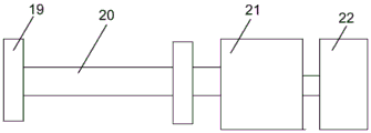
fig. 2 is a schematic structural diagram of a winding device provided by the utility model.
In the figure, 100, an aluminum strip residual coil rewinding machine 1, a rack 2, an uncoiling device 3, a tension device 4, a coiling device 5, a first bearing seat 6, a second bearing seat 7, a sleeve 8, a first material supporting roller 9, a second material supporting roller 10, a first support 11, a second support 12, a third bearing seat 13, a fourth bearing seat 14, a first guide roller 15, a second guide roller 16, a clamping plate member 161, an upper clamping plate 162, a lower clamping plate 17, a cylinder 18, a third support 19, a fifth bearing seat 20, a coiling shaft 21, a speed reducer 22, a driving member 23, a baffle rubber roller stripping 24, a supporting plate 25, a guide groove 26, wool felt cloth 27 and an ear ring.
[ detailed description ] embodiments
The technical solutions in the embodiments of the present invention will be clearly and completely described below with reference to the drawings in the embodiments of the present invention, and it is obvious that the described embodiments are only a part of the embodiments of the present invention, and not all of the embodiments. All other embodiments, which can be derived by a person skilled in the art from the embodiments given herein without making any creative effort, shall fall within the protection scope of the present invention.
Referring to fig. 1-2, the utility model provides an aluminum strip residual coil rewinding machine 100 for processing waste aluminum strips, which comprises a frame 1, an uncoiling device 2 arranged at one end of the frame 1, a coiling device 4 arranged at the other end of the frame 1, and a tension device 3 arranged between the uncoiling device 2 and the coiling device 4, wherein the aluminum strips are sequentially coiled from the uncoiling device 2, the tension device 3 to the coiling device 4. The residual coil is placed on the uncoiling device 2, uncoiled through the uncoiling device 2, fixed on the coiling device 4 through the tension device 3, and automatically collected through the coiling device 4. Therefore, the rewinding machine is simple and reliable in structure, small in occupied area, low in manufacturing and running cost and convenient to operate and maintain.
The uncoiling device 2 comprises a first bearing seat 5, a second bearing seat 6, a first material supporting roller 8, a second material supporting roller 9 and a sleeve 7, wherein the first bearing seat 5 and the second bearing seat 6 are relatively fixed at one end of the rack 1, the first material supporting roller 8 is arranged on the first bearing seat 5, the second material supporting roller 9 is arranged on the second bearing seat 6, the sleeve 7 winds the aluminum strip, and the sleeve 7 is placed between the first material supporting roller 8 and the second material supporting roller 9. The first bearing seat 5 and the second bearing seat 6 are fixed at one end, and the first material supporting roller 8 and the second material supporting roller 9 are respectively arranged on the first bearing seat 5 and the second bearing seat 6, so that the first material supporting roller 8 and the second material supporting roller 9 can rotate conveniently. And the sleeve 7 with the residual coil is arranged between the first material supporting roller 8 and the second material supporting roller 9, when the residual coil aluminum strip is uncoiled, the sleeve 7 is driven to rotate between the first material supporting roller 8 and the second material supporting roller 9 along with the coiling device 4 to coil the residual coil and uncoil, and the support effect is good and the use is convenient.
The tension device 3 comprises a first support 10 fixed on the frame 1, a second support 11 arranged on the first support 10, a third bearing seat 12 and a fourth bearing seat 13 which are arranged on two sides of the second support 11 and fixed on the first support 10, a first guide roller 14 arranged on the third bearing seat 12, a second guide roller 15 arranged on the fourth bearing seat 13, a clamping plate member 16 arranged on the second support 11 and a cylinder 17 arranged on the second support 11 and used for driving the clamping plate member 16 to clamp the aluminum strip. By providing the first bracket 10 and the second bracket 11 on the frame 1, it is convenient to install the third bearing housing 12, the fourth bearing housing 13, the first guide roller 14, the second guide roller 15, the clamp member 16, and the air cylinder 17, respectively. The first support 10 is at a certain distance from the support of the frame 1, so that the residual coil uncoiled on the uncoiling device 2 is coiled to an upward pulling force to tension the residual coil, thereby facilitating the coiling treatment of the residual coil by the coiling device 4. The first guide roller 14 and the second guide roller 15 facilitate the smooth diversion of the strip into and out of the tensioner by passing the stub roll sequentially through the first guide roller 14, the nip member 16, the second guide roller 15 onto the take-up 4. Wherein, the cylinder 17 is two, sets up on second support 11 relatively, drives the both ends of splint component 16 through two cylinders 17 and carries out tension control to incomplete book and adjust, and it is more convenient that incomplete book is rolled up on coiling apparatus 4.
In this embodiment, the winding device 4 includes a third bracket 18 fixed to the other end of the frame 1, a fifth bearing seat 19 disposed on the third bracket 18, a winding shaft 20 disposed on the fifth bearing seat 19, a speed reducer 21 connected to one end of the winding shaft 20 in a transmission manner, and a driving member 22 connected to the speed reducer 21 in a transmission manner. The driving member 22 drives the speed reducer 21 to rotate, the speed reducer 21 drives the winding shaft 20 arranged on the fifth bearing seat 19 to rotate, the residual coil is arranged on the winding shaft 20, and the residual coil can be wound by the rotation of the winding shaft 20.
The fifth bearing seat 19 is detachably fixed on the third bracket 18, so that the winding shaft 20 can be conveniently dismounted. The strip can be fixed on the coiling shaft 20 by using an adhesive tape, so that the aluminum sleeve 7 is not added, the tension is removed after the coiling is finished, the inner ring of the residual coil can rebound a little to be enlarged, and the air expansion shaft can smoothly unload materials after the diameter is reduced.
In this embodiment, the tension device 3 further includes a supporting plate 24 fixed on one side of the first bracket 10 close to the unwinding device 2, and a roll blocking and peeling rubber roller 23 disposed on the supporting plate 24. The backup pad 24 is used for the installation to set up and keep off the book and shell rubber roll 23, through keeping off the below that the rubber roll 23 was shelled to the book with the aluminium strip setting, utilizes the taut aluminium strip of coiling apparatus 4, and tension device 3 through middle setting provides tension for keep off the book and shell rubber roll 23 and can place the incomplete book and roll out, can also tear the sticky tape that the strip afterbody glues on sleeve 7 simultaneously.
In this embodiment, the second bracket 11 is formed with a guide groove 25 extending inward, and both ends of the clamp member 16 are fitted into the guide groove 25. The arrangement of the clamping plate member 16 is convenient, so that the air cylinder 17 drives the clamping plate member 16 to clamp the aluminum strip more conveniently.
In the present embodiment, the clamp member 16 includes an upper clamp 161 and a lower clamp 162 oppositely disposed in the guide groove 25, and the aluminum strip is disposed between the upper clamp 161 and the lower clamp 162. The tension device 3 is designed into the form of the upper clamping plate 162 and the lower clamping plate 162, the lower clamping plate 162 is fixed on the frame 1, the upper clamping plate 161 is fixed on the output shaft of the air cylinder 17, the tension is improved for the passed residual coil through the air cylinder 17 by the upper clamping plate 161 and the lower clamping plate 162, so that the residual coil of the coiling device 4 obtains enough coiling tension, and the coiling is smoothly completed.
In this embodiment, the upper and lower nip plates 161 and 162 are covered with the felt 26, respectively. The upper and lower nip plates 161 and 162 are respectively coated with felt 26 to increase friction, and the band passes through the nip of the nip plates.
In this embodiment, the cylinder 17 is fixedly connected to the clamp member 16 by an ear ring 27. The two cylinders 17 at two ends drive the upper clamping plate 161 of the fixed earring 27 to move up and down, and as the clamping plate is coated with the wool felt cloth, friction force is formed between the clamping plate and the surface of the aluminum strip under the action of pressure when the clamping plate moves down, namely tension is established between the clamping plate and a coiling machine; when the splint moved up, it separated from the aluminum plate and the tension disappeared.
In this embodiment, the driving member 22 is an ac motor, and is controlled by a frequency converter, so as to achieve the effect of stepless speed change.
In the present embodiment, the winding shaft 20 is an air-inflation type winding shaft 20. The air is conveniently exhausted through the air release valve at the shaft end after the winding is finished, and the air expansion shaft can smoothly discharge the material after the diameter is reduced.
While the foregoing is directed to embodiments of the present invention, it will be understood by those skilled in the art that various changes may be made without departing from the spirit and scope of the utility model.
Claims (9)
1. A residual coil rewinding machine for aluminum strip materials is used for processing waste aluminum strip materials and is characterized by comprising a rack, an uncoiling device arranged at one end of the rack, a coiling device arranged at the other end of the rack and a tension device arranged between the uncoiling device and the coiling device, wherein the aluminum strip materials are coiled from the uncoiling device, the tension device and the coiling device in sequence;
the uncoiling device comprises a first bearing seat, a second bearing seat, a first material supporting roller, a second material supporting roller and a sleeve, wherein the first bearing seat and the second bearing seat are relatively fixed on one end of the rack;
tension device is including being fixed in relatively first support in the frame, set up in second support on the first support, set up relatively the second support both sides are fixed in third bearing seat, fourth bearing seat of first support, set up in first deflector roll on the third bearing seat, set up in second deflector roll on the fourth bearing seat, set up in splint component on the second support and set up in on the second support and be used for the drive the splint component presss from both sides tightly the cylinder of aluminium strip.
2. The aluminum strip residual coil rewinding machine as claimed in claim 1, wherein the rewinding device comprises a third bracket relatively fixed to the other end of the rack, a fifth bearing seat arranged on the third bracket, a winding shaft arranged on the fifth bearing seat, a speed reducer in transmission connection with one end of the winding shaft, and a driving member in transmission connection with the speed reducer.
3. The aluminum strip residual coil rewinding machine as claimed in claim 1, wherein the tension device further comprises a support plate fixed on one side of the first support close to the unwinding device and a coil blocking and peeling rubber roller arranged on the support plate.
4. The aluminum strip stub roll rewinding machine as claimed in claim 1, wherein said second support extends inwardly to form a guide slot, and wherein said clamping plate member is fitted at both ends thereof into said guide slot.
5. The aluminum strip stub roll winder of claim 4 wherein the clamp member includes an upper clamp and a lower clamp oppositely disposed in the guide slot, the aluminum strip being disposed between the upper clamp and the lower clamp.
6. The aluminum strip stub roll rewinding machine as claimed in claim 5, wherein said upper and lower clamping plates are respectively coated with a felt.
7. The aluminum strip stub roll rewinding machine as claimed in claim 1, wherein said cylinder is fixedly connected to said clamping plate member by means of an earring.
8. The stub aluminum strip rewind reel of claim 2 wherein said drive is an air-tensioned spool coiler.
9. The stub aluminum strip rewind as claimed in claim 2 wherein said take-up spool is an air-filled take-up spool.
Priority Applications (1)
| Application Number | Priority Date | Filing Date | Title |
|---|---|---|---|
| CN202122343472.5U CN215974422U (en) | 2021-09-26 | 2021-09-26 | Incomplete book rewinder of aluminium strip material |
Applications Claiming Priority (1)
| Application Number | Priority Date | Filing Date | Title |
|---|---|---|---|
| CN202122343472.5U CN215974422U (en) | 2021-09-26 | 2021-09-26 | Incomplete book rewinder of aluminium strip material |
Publications (1)
| Publication Number | Publication Date |
|---|---|
| CN215974422U true CN215974422U (en) | 2022-03-08 |
Family
ID=80571084
Family Applications (1)
| Application Number | Title | Priority Date | Filing Date |
|---|---|---|---|
| CN202122343472.5U Active CN215974422U (en) | 2021-09-26 | 2021-09-26 | Incomplete book rewinder of aluminium strip material |
Country Status (1)
| Country | Link |
|---|---|
| CN (1) | CN215974422U (en) |
-
2021
- 2021-09-26 CN CN202122343472.5U patent/CN215974422U/en active Active
Similar Documents
| Publication | Publication Date | Title |
|---|---|---|
| CN108190585B (en) | Automatic stripping and connecting device for winding of compound machine | |
| CN215974422U (en) | Incomplete book rewinder of aluminium strip material | |
| CN111807110A (en) | Automatic rolling device for tearing cloth of tire bead ring wrapping cloth | |
| CN213111831U (en) | Toilet paper production coiling mechanism | |
| CN201891005U (en) | Cloth cover drawing device | |
| CN2487714Y (en) | Automatic web roll mounting blowing device for winding machine | |
| CN211920318U (en) | Feeding device and film cutting machine | |
| CN211812524U (en) | From type scroll rewinding machine | |
| CN114798743A (en) | Rewinding process for strip steel recoiling machine | |
| CN115246591A (en) | Film winding and unwinding device capable of automatically changing roll and control method thereof | |
| CN212831761U (en) | Automatic rolling device for tearing cloth of tire bead ring wrapping cloth | |
| CN208761778U (en) | A kind of coiler | |
| CN216686793U (en) | Slip sheet coiling mechanism | |
| CN218275851U (en) | Automatic cable stripping machine | |
| CN220316787U (en) | Film rewinder | |
| CN220537078U (en) | Large-scale rewinding machine for insulating paper | |
| CN111703131A (en) | Filter paper winder of filter production usefulness | |
| CN219929124U (en) | Duplex position broken film vacuum rolling equipment | |
| CN214003547U (en) | Unwinding device of non-woven fabric roll moisture-proof film packaging equipment | |
| CN110667100A (en) | Film coating equipment and roll changing mechanism thereof | |
| CN215047371U (en) | Isolating film finishing and rewinding device | |
| CN217498302U (en) | Automatic lap of package device of coating aluminium foil | |
| CN209779283U (en) | Dustless cloth cutting machine | |
| CN219859684U (en) | Material belt winding device | |
| CN216863064U (en) | PET release film splitting machine |
Legal Events
| Date | Code | Title | Description |
|---|---|---|---|
| GR01 | Patent grant | ||
| GR01 | Patent grant |