CN215967384U - Full-automatic efficient energy-saving longitudinal shearing production line - Google Patents
Full-automatic efficient energy-saving longitudinal shearing production line Download PDFInfo
- Publication number
- CN215967384U CN215967384U CN202122764178.1U CN202122764178U CN215967384U CN 215967384 U CN215967384 U CN 215967384U CN 202122764178 U CN202122764178 U CN 202122764178U CN 215967384 U CN215967384 U CN 215967384U
- Authority
- CN
- China
- Prior art keywords
- support
- bolted
- transmission device
- bearing
- production line
- Prior art date
- Legal status (The legal status is an assumption and is not a legal conclusion. Google has not performed a legal analysis and makes no representation as to the accuracy of the status listed.)
- Active
Links
Images


Landscapes
- Shearing Machines (AREA)
Abstract
The utility model relates to the technical field of longitudinal shearing equipment and discloses a full-automatic efficient energy-saving longitudinal shearing production line which comprises a transmission device, wherein the top of the transmission device is bolted with a longitudinal shearing machine, one side of the transmission device is provided with a support, and the inside of the support is rotatably connected with a rotating roller through a bearing; according to the utility model, the coiled material is sleeved on the surface of the discharging wheel, one end of the coiled material penetrates through the space between the rotating roller and the moving roller, then the coiled material is transmitted at the top of the transmission device, and is cut when passing through the interior of the slitting machine, and then the rotating roller is driven to rotate by the first motor, so that the coiled material can be effectively leveled by the matching of the rotating roller and the moving roller; according to the utility model, the turntable drives the connecting block to move through the matching of the connecting bearing by rotating the turntable, and then the connecting block drives the moving roller to adjust up and down through the matching of the moving bearing, so that a user can conveniently adjust according to the thickness of the coiled material.
Description
Technical Field
The utility model relates to the technical field of longitudinal shearing equipment, in particular to a full-automatic efficient energy-saving longitudinal shearing production line.
Background
A disk slitting machine belongs to a device for slitting metal plates and is a production line consisting of uncoiling, feeding, shearing, coiling and other devices. The material for production and processing can be selected from hard alloy, alloy steel, high-speed steel, tungsten steel, stainless steel and other materials. But current indulge and cut production line can not effectively carry out the flattening to the coiled material, still can not effectively adjust according to the thickness of coiled material simultaneously to reduce its practicality, for solving above-mentioned problem, we provide a full-automatic energy-efficient indulge and cut production line.
SUMMERY OF THE UTILITY MODEL
The utility model aims to provide a full-automatic efficient energy-saving longitudinal shearing production line, which has the advantages of effectively leveling coiled materials and effectively adjusting according to the thickness of the coiled materials, and solves the problems that the existing longitudinal shearing production line cannot effectively level the coiled materials and cannot effectively adjust according to the thickness of the coiled materials.
In order to achieve the purpose, the utility model provides the following technical scheme: a full-automatic high-efficiency energy-saving longitudinal shearing production line comprises a transmission device, wherein the top of the transmission device is bolted with a longitudinal shearing machine, a bracket is arranged on one side of the transmission device, the inside of the bracket is rotationally connected with a rotating roller through a bearing, the back of the bracket is bolted with a first motor, the output end of the first motor is bolted with the rotating roller, the top of the rotating roller is provided with a moving roller, the two sides of the bracket are both provided with sliding grooves, the inside of each sliding groove is connected with a connecting block in a sliding way, the bottom of the connecting block is bolted with a movable bearing, the interior of the movable bearing is sleeved with the movable roller, the inner part of the bracket is connected with a threaded rod through threads, the bottom of the threaded rod is sleeved with a connecting bearing, the bottom of the connecting bearing is bolted with the connecting block, one side of the support is provided with a support, and the inside of the support is rotatably connected with a discharging wheel.
Preferably, one side of the conveying device is provided with a supporting seat, and the top of the supporting seat is rotatably connected with a winding wheel through a bearing.
Preferably, one end of the winding wheel is sleeved with a first gear, the surface of the first gear is sleeved with a chain, the top of the supporting seat is bolted with a second motor, the output end of the second motor is sleeved with a second gear, and the surface of the chain is sleeved with the second gear.
Preferably, the top of the threaded rod is sleeved with a turntable, and the surface of the turntable is sleeved with anti-skid lines.
Preferably, a first connecting frame is bolted to one side of the supporting seat, and the other end of the first connecting frame is bolted to the transmission device.
Preferably, one side of the transmission device is bolted with a second connecting frame, the other end of the second connecting frame is bolted with the support, one side of the support is bolted with a third connecting frame, and the other end of the third connecting frame is bolted with the support.
Compared with the prior art, the utility model has the following beneficial effects:
according to the utility model, the coiled material is sleeved on the surface of the discharging wheel, one end of the coiled material penetrates through the space between the rotating roller and the moving roller, then the coiled material is transmitted at the top of the transmission device, and is cut when passing through the interior of the slitting machine, and then the rotating roller is driven to rotate by the first motor, so that the coiled material can be effectively leveled by the matching of the rotating roller and the moving roller;
according to the utility model, the turntable drives the connecting block to move through the matching of the connecting bearing by rotating the turntable, and then the connecting block drives the moving roller to adjust up and down through the matching of the moving bearing, so that a user can conveniently adjust according to the thickness of the coiled material.
Drawings
FIG. 1 is a front view of the structure of the present invention;
FIG. 2 is a side view of a portion of the structure of the present invention;
fig. 3 is a partial enlarged view of the utility model at a in fig. 1.
In the figure: 1. a transmission device; 2. a slitting machine; 3. a support; 4. a rotating roller; 5. a first motor; 6. a moving roller; 7. a chute; 8. moving the bearing; 9. connecting blocks; 10. a threaded rod; 11. a support; 12. a discharge wheel; 13. a supporting seat; 14. a winding wheel; 15. a first gear; 16. a chain; 17. a second motor; 18. a turntable; 19. a first connecting frame; 20. a second link frame; 21. a third connecting frame; 22. and connecting the bearing.
Detailed Description
The technical solutions in the embodiments of the present invention will be clearly and completely described below with reference to the drawings in the embodiments of the present invention, and it is obvious that the described embodiments are only a part of the embodiments of the present invention, and not all of the embodiments. All other embodiments, which can be derived by a person skilled in the art from the embodiments given herein without making any creative effort, shall fall within the protection scope of the present invention.
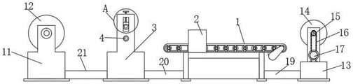
Referring to fig. 1-3, a full-automatic, efficient, energy-saving and longitudinal shearing production line comprises a transmission device 1, a longitudinal shearing machine 2 is bolted to the top of the transmission device 1, a support 3 is arranged on one side of the transmission device 1, a rotating roller 4 is rotatably connected inside the support 3 through a bearing, a first motor 5 is bolted to the back of the support 3, the output end of the first motor 5 is bolted to the rotating roller 4, a moving roller 6 is arranged on the top of the rotating roller 4, sliding grooves 7 are formed in two sides of the support 3, a connecting block 9 is slidably connected inside the sliding grooves 7, a moving bearing 8 is bolted to the bottom of the connecting block 9, the inside of the moving bearing 8 is sleeved to the moving roller 6, a threaded rod 10 is connected to the inside of the support 3, a connecting bearing 22 is sleeved to the bottom of the threaded rod 10, the bottom of the connecting bearing 22 is bolted to the connecting block 9, a support 11 is arranged on one side of the support 3, and a discharging wheel 12 is rotatably connected to the inside of the support 11.
Further, one side of transmission device 1 is provided with supporting seat 13, and the top of supporting seat 13 is connected with rolling wheel 14 through the bearing rotation, through setting up rolling wheel 14, can effectively carry out the rolling to the coiled material after cuting.
Further, first gear 15 has been cup jointed to the one end of rolling wheel 14, and chain 16 has been cup jointed on the surface of first gear 15, and the top bolt of supporting seat 13 has been connected with second motor 17, and the output of second motor 17 has cup jointed the second gear, and the surface and the second gear of chain 16 cup joint, through setting up second motor 17, can effectively drive rolling wheel 14.
Further, the top of the threaded rod 10 is sleeved with a rotating disc 18, the surface of the rotating disc 18 is sleeved with anti-slip threads, and the threaded rod 10 can be rotated conveniently by a user through the arrangement of the rotating disc 18.
Furthermore, one side of the supporting seat 13 is bolted with a first connecting frame 19, the other end of the first connecting frame 19 is bolted with the transmission device 1, and the supporting seat 13 can be effectively connected with the transmission device 1 by arranging the first connecting frame 19.
Further, one side of the transmission device 1 is bolted with a second connecting frame 20, the other end of the second connecting frame 20 is bolted with the support 3, one side of the support 3 is bolted with a third connecting frame 21, the other end of the third connecting frame 21 is bolted with the support 11, and the support 3 can be effectively connected with the support 11 by arranging the third connecting frame 21.
The working principle is as follows: the user overlaps the coiled material on the surface of blowing wheel 12, pass live-rollers 4 and remove between the roller 6 with the one end of coiled material afterwards, transmit at transmission device 1's top afterwards, cut when indulging the inside of shearing machine 2 again, drive live-rollers 4 through first motor 5 afterwards and rotate, the cooperation that makes live-rollers 4 and removal roller 6 can effectively carry out the flattening to the coiled material, user can rotate carousel 18 simultaneously, make carousel 18 drive connecting block 9 through the cooperation of connecting bearing 22 and remove, connecting block 9 drives through the cooperation of removing bearing 8 and removes roller 6 and adjust from top to bottom afterwards, thereby the person of facilitating the use can effectively adjust according to the thickness of coiled material.
It is noted that, herein, relational terms such as first and second, and the like may be used solely to distinguish one entity or action from another entity or action without necessarily requiring or implying any actual such relationship or order between such entities or actions. Also, the terms "comprises," "comprising," or any other variation thereof, are intended to cover a non-exclusive inclusion, such that a process, method, article, or apparatus that comprises a list of elements does not include only those elements but may include other elements not expressly listed or inherent to such process, method, article, or apparatus. Without further limitation, an element defined by the phrase "comprising an … …" does not exclude the presence of other identical elements in a process, method, article, or apparatus that comprises the element.
Although embodiments of the present invention have been shown and described, it will be appreciated by those skilled in the art that changes, modifications, substitutions and alterations can be made in these embodiments without departing from the principles and spirit of the utility model, the scope of which is defined in the appended claims and their equivalents.
Claims (6)
1. The utility model provides a full-automatic energy-efficient indulges and cuts production line, includes transmission device (1), its characterized in that: the top of the transmission device (1) is bolted with a slitting machine (2), one side of the transmission device (1) is provided with a support (3), the inside of the support (3) is rotatably connected with a rotating roller (4) through a bearing, the back of the support (3) is bolted with a first motor (5), the output end of the first motor (5) is bolted with the rotating roller (4), the top of the rotating roller (4) is provided with a moving roller (6), two sides of the support (3) are both provided with sliding grooves (7), the inside of the sliding grooves (7) is slidably connected with a connecting block (9), the bottom of the connecting block (9) is bolted with a moving bearing (8), the inside of the moving bearing (8) is sleeved with the moving roller (6), the inside of the support (3) is in threaded connection with a threaded rod (10), the bottom of the threaded rod (10) is sleeved with a connecting bearing (22), the bottom of the connecting bearing (22) is bolted with the connecting block (9), a support (11) is arranged on one side of the support (3), and a discharging wheel (12) is rotatably connected inside the support (11).
2. The full-automatic efficient energy-saving slitting production line according to claim 1 is characterized in that: one side of the conveying device (1) is provided with a supporting seat (13), and the top of the supporting seat (13) is rotatably connected with a winding wheel (14) through a bearing.
3. The full-automatic efficient energy-saving slitting production line according to claim 2 is characterized in that: first gear (15) have been cup jointed to the one end of rolling wheel (14), chain (16) have been cup jointed on the surface of first gear (15), the top bolt joint of supporting seat (13) has second motor (17), the output of second motor (17) has cup jointed the second gear, the surface and the second gear of chain (16) cup joint.
4. The full-automatic efficient energy-saving slitting production line according to claim 1 is characterized in that: the top of the threaded rod (10) is sleeved with a rotary table (18), and the surface of the rotary table (18) is sleeved with anti-skid lines.
5. The full-automatic efficient energy-saving slitting production line according to claim 2 is characterized in that: one side of the supporting seat (13) is in bolted connection with a first connecting frame (19), and the other end of the first connecting frame (19) is in bolted connection with the transmission device (1).
6. The full-automatic efficient energy-saving slitting production line according to claim 1 is characterized in that: one side of the transmission device (1) is in bolted connection with a second connecting frame (20), the other end of the second connecting frame (20) is in bolted connection with the support (3), one side of the support (3) is in bolted connection with a third connecting frame (21), and the other end of the third connecting frame (21) is in bolted connection with the support (11).
Priority Applications (1)
| Application Number | Priority Date | Filing Date | Title |
|---|---|---|---|
| CN202122764178.1U CN215967384U (en) | 2021-11-12 | 2021-11-12 | Full-automatic efficient energy-saving longitudinal shearing production line |
Applications Claiming Priority (1)
| Application Number | Priority Date | Filing Date | Title |
|---|---|---|---|
| CN202122764178.1U CN215967384U (en) | 2021-11-12 | 2021-11-12 | Full-automatic efficient energy-saving longitudinal shearing production line |
Publications (1)
| Publication Number | Publication Date |
|---|---|
| CN215967384U true CN215967384U (en) | 2022-03-08 |
Family
ID=80510701
Family Applications (1)
| Application Number | Title | Priority Date | Filing Date |
|---|---|---|---|
| CN202122764178.1U Active CN215967384U (en) | 2021-11-12 | 2021-11-12 | Full-automatic efficient energy-saving longitudinal shearing production line |
Country Status (1)
| Country | Link |
|---|---|
| CN (1) | CN215967384U (en) |
-
2021
- 2021-11-12 CN CN202122764178.1U patent/CN215967384U/en active Active
Similar Documents
| Publication | Publication Date | Title |
|---|---|---|
| CN215967384U (en) | Full-automatic efficient energy-saving longitudinal shearing production line | |
| CN110103271B (en) | Automatic paper cutter for roll paper | |
| CN211276723U (en) | Positioning and cutting device for processing protective welded pipe | |
| CN210548430U (en) | Slitting machine | |
| CN217345596U (en) | Stone paper production line rim charge cuts equipment | |
| CN210650643U (en) | Steel support is used in saw bit production | |
| CN206985038U (en) | A kind of foamed ceramic scrapper conveyor automatic material clearing mechanism | |
| CN111941496A (en) | Roll paper cutter that cutting efficiency is high | |
| CN211842191U (en) | Cutting auxiliary device is used in processing of solid wall pipe | |
| CN208895286U (en) | A kind of re-reeler thin aluminium strip cutting device | |
| CN209937029U (en) | Rubber product cutting device | |
| CN113211531A (en) | Mpp cable protection pipe processing cutting device | |
| CN211164136U (en) | Rubber processing production slitting equipment | |
| CN210157981U (en) | High-efficient ball machine | |
| CN211522780U (en) | Adjustment mechanism of joint cutter for road construction | |
| CN2329187Y (en) | Machine for peeling and removing bur of pineapple | |
| CN212312853U (en) | Spiral pipe outer support frame with weld scar processing mechanism | |
| CN206263007U (en) | Vertical free blanking side silk machine | |
| CN219211076U (en) | Section mill | |
| CN212886695U (en) | Slitting machine for steel pipe machining | |
| CN220665794U (en) | Automatic paper bag hot cutting machine | |
| CN218836219U (en) | Quantitative cutting device for aluminum cutting pellets | |
| CN218801152U (en) | Metal product edge folding machine with controllable rotating speed | |
| CN216682991U (en) | Plastic product trimming equipment for production | |
| CN214359382U (en) | Frame is cut to plastic wrap |
Legal Events
| Date | Code | Title | Description |
|---|---|---|---|
| GR01 | Patent grant | ||
| GR01 | Patent grant |