CN215963273U - Disinfectant diluting device for pet supplies - Google Patents
Disinfectant diluting device for pet supplies Download PDFInfo
- Publication number
- CN215963273U CN215963273U CN202122426063.1U CN202122426063U CN215963273U CN 215963273 U CN215963273 U CN 215963273U CN 202122426063 U CN202122426063 U CN 202122426063U CN 215963273 U CN215963273 U CN 215963273U
- Authority
- CN
- China
- Prior art keywords
- mixing barrel
- threaded rod
- groove
- stirring frame
- water
- Prior art date
- Legal status (The legal status is an assumption and is not a legal conclusion. Google has not performed a legal analysis and makes no representation as to the accuracy of the status listed.)
- Active
Links
Images

Abstract
The utility model belongs to the technical field of pet products, and discloses a disinfectant diluting device for pet products, which comprises a mixing barrel, wherein the top of the mixing barrel is movably connected with a sealing cover, the inner wall of the mixing barrel is provided with a mounting groove, the inside of the mixing barrel is provided with a guide groove positioned at the bottom of the mounting groove, the inside of the guide groove is fixedly sleeved with a guide pipe, and the bottom of the guide pipe is fixedly communicated with a splash-proof plate positioned in the mounting groove. According to the utility model, the guide groove, the guide pipe and the conical filter screen are arranged, water injected into the water inlet groove can be filtered through the conical filter screen, so that the water can flow into the hose through the water inlet groove, the falling water can be ensured to slide along the inner wall of the guide groove under the action of the guide pipe and the splash-preventing plate, and then the water stably falls to the bottom of the mixing barrel and is finally mixed with the medicament, so that the condition that the medicament is lost due to the fact that the water impacts the medicament is greatly reduced.
Description
Technical Field
The utility model belongs to the technical field of pet supplies, and particularly relates to a disinfectant diluting device for a pet supply.
Background
The disinfectant is a medicine for killing pathogenic microorganisms on a transmission medium, and is used for killing the pathogenic microorganisms outside a human body, cutting off the transmission path of infectious diseases and achieving the purpose of controlling the infectious diseases; the disinfectant can be divided into a sterilizing agent, a high-efficiency disinfectant, a middle-efficiency disinfectant and a low-efficiency disinfectant according to the action level; the disinfectant is an essential product in pet breeding.
At present, in the dilution operation of the disinfectant, a required amount of water is required to be poured into the liquid medicine, and the water is injected into the liquid medicine while causing the liquid medicine to splash to the inner wall of the container due to the impact of the water and the liquid medicine, thereby causing the loss of the liquid medicine, so that the concentration of the diluted liquid medicine is lower than the expected concentration, and therefore, the improvement is required.
Simultaneously, need water and medicament fast and intensive mixing when utilizing water to dilute the medicament, and current dilution container does not generally have better mixing stirring mechanism, and then can't fast intensive mixing when leading to water and medicament to can reduce dilution efficiency, though current dilution equipment also can use stirring mechanism, it appears mixed liquid and puddler simultaneous movement easily and is difficult to reach the effect of rapid mixing, consequently also needs to improve it.
SUMMERY OF THE UTILITY MODEL
The utility model aims to solve the problems and provides a disinfectant diluting device for pet products, which has the advantages of less loss and high mixing efficiency.
In order to achieve the purpose, the utility model provides the following technical scheme: a disinfectant diluting device for pet articles comprises a mixing barrel, wherein a sealing cover is movably connected to the top of the mixing barrel, a mounting groove is formed in the inner wall of the mixing barrel, a flow guide groove is formed in the bottom of the mounting groove in the mixing barrel, a flow guide pipe is fixedly sleeved in the flow guide groove, a splash-proof plate is fixedly communicated with the bottom of the flow guide pipe in the mounting groove, the top of the flow guide pipe penetrates through the flow guide groove, extends to the upper portion of the mixing barrel and is fixedly communicated with a hose in the sealing cover, a water inlet groove is movably sleeved at the top of the sealing cover, the bottom of the water inlet groove is fixedly communicated with the top of the hose, a conical filter screen positioned above the left side of the hose is movably clamped in the inner part of the water inlet groove, good flow guide can be carried out on water due to the arrangement of the mounting groove, and the situation that the water is separated from the mounting groove and the flow guide groove in the transmission process and falls into the mixing barrel to cause medicament splash is avoided, and the stability of water transmission can be further ensured under the matching of the draft tube and the splash-proof plate.
According to the preferable technical scheme, the bottom of the inner cavity of the mixing barrel is movably connected with a threaded rod, the outer surface of the threaded rod is in threaded sleeve connection with the stirring frame, the number sum of the threaded rod and the stirring frame is three, the threaded rod and the stirring frame are uniformly distributed in the mixing barrel, mixed liquid in the mixing barrel can be stirred and mixed through the arranged stirring frame, and meanwhile, due to synchronous rotation of the three stirring frames, the situation that the mixed liquid cannot achieve stirring and mixing effects due to rotation of the stirring device can be avoided.
As a preferred technical scheme, the outer surface of the threaded rod is movably sleeved with a sliding sleeve positioned at the bottom of the stirring frame, the top of the sliding sleeve is movably connected with the bottom of the stirring frame, and the reset spring can be connected due to the arrangement of the sliding sleeve, so that the situation that the reset spring is twisted due to the influence on the reset spring when the stirring frame rotates is avoided.
As a preferred technical scheme of the utility model, the outer surface of the threaded rod is movably sleeved with a return spring positioned at the bottom of the sliding sleeve, the upper end and the lower end of the return spring are respectively fixedly connected with the bottom of the sliding sleeve and the bottom of the inner cavity of the mixing barrel, the return spring can be contracted under the push of the stirring frame and the sliding sleeve and has elastic force recovery performance, and the stirring frame can be pushed to reset through the sliding sleeve by utilizing the elastic force recovery effect of the return spring.
As a preferable technical scheme of the utility model, the outer surface of the threaded rod is movably sleeved with a movable loop bar positioned at the top of the stirring frame, the bottom of the movable loop bar is movably connected with the top of the stirring frame, the outer surface of the movable loop bar is movably connected with the inner wall of the sealing cover, and due to the arrangement of the movable loop bar, the effect of stably pushing the stirring frame can be achieved under the limitation of the threaded rod, so that the stirring frame can rotate to stir mixed liquid under the coordination of the threaded rod.
According to a preferable technical scheme of the utility model, the top of the movable sleeve rod penetrates through the mixing barrel, extends to the upper part of the sealing cover and is fixedly connected with the pushing frame, the bottom of the pushing frame is movably connected with the top of the sealing cover, and through the arranged pushing frame, a worker can conveniently press the pushing frame and achieve the function of moving the stirring frame through the movable sleeve rod, so that the stirring frame can be rotated downwards under the action of the threaded rod.
Compared with the prior art, the utility model has the following beneficial effects:
1. according to the utility model, the guide groove, the guide pipe, the hose and the conical filter screen are arranged, water injected into the water inlet groove can be filtered through the conical filter screen, so that the water can flow into the hose through the water inlet groove, the falling water can be ensured to slide along the inner wall of the guide groove under the action of the guide pipe and the splash-preventing plate, and then the water stably falls to the bottom of the mixing barrel and is finally mixed with the medicament, so that the condition that the medicament is lost due to the fact that the water impacts the medicament is greatly reduced.
2. According to the stirring device, the threaded rod, the stirring frame, the reset spring and the pushing frame are arranged, the pushing frame can be pressed to push the stirring frame to move through the movable sleeve rod, the stirring frame can rotate downwards under the matching of the threaded rod, so that a good stirring and mixing effect can be achieved on mixed liquid, the situation that the reset spring is distorted when the stirring frame rotates can be avoided through the sliding sleeve, and therefore the reset spring can be enabled to push the stirring frame to reset to move by utilizing the self elastic recovery action of the reset spring in the later stage.
Drawings
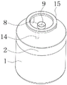
FIG. 1 is a schematic structural view of the present invention;
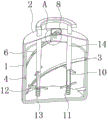
FIG. 2 is a schematic cross-sectional front view of the present invention;
FIG. 3 is a side cross-sectional structural schematic view of the present invention;
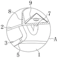
FIG. 4 is a schematic view of a portion of the enlarged structure at A in FIG. 2;
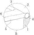
fig. 5 is a partially enlarged structural view at B in fig. 3.
In the figure: 1. a mixing barrel; 2. a sealing cover; 3. mounting grooves; 4. a diversion trench; 5. a flow guide pipe; 6. a splash prevention plate; 7. a hose; 8. a water inlet groove; 9. a conical filter screen; 10. a threaded rod; 11. a stirring frame; 12. a sliding sleeve; 13. a return spring; 14. a movable loop bar; 15. and a pushing frame.
Detailed Description
The technical solutions in the embodiments of the present invention will be clearly and completely described below with reference to the drawings in the embodiments of the present invention, and it is obvious that the described embodiments are only a part of the embodiments of the present invention, and not all of the embodiments. All other embodiments, which can be derived by a person skilled in the art from the embodiments given herein without making any creative effort, shall fall within the protection scope of the present invention.
As shown in fig. 1 to 5, the utility model provides a disinfectant diluting device for pet products, which comprises a mixing barrel 1, wherein the top of the mixing barrel 1 is movably connected with a sealing cover 2, the inner wall of the mixing barrel 1 is provided with a mounting groove 3, the interior of the mixing barrel 1 is provided with a flow guide groove 4 positioned at the bottom of the mounting groove 3, the interior of the flow guide groove 4 is fixedly sleeved with a flow guide pipe 5, the bottom of the flow guide pipe 5 is fixedly communicated with a splash-proof plate 6 positioned inside the mounting groove 3, the top of the flow guide pipe 5 penetrates through the flow guide groove 4 and extends to the upper part of the mixing barrel 1 and is fixedly communicated with a hose 7 positioned inside the sealing cover 2, the top of the sealing cover 2 is movably sleeved with a water inlet groove 8, the bottom of the water inlet groove 8 is fixedly communicated with the top of the hose 7, the interior of the water inlet groove 8 is movably clamped with a conical filter screen 9 positioned on the upper left side of the hose 7, and good water flow guide can be performed due to the arrangement of the mounting groove 3, further, the situation that the water is separated from the mounting groove 3 and the flow guide groove 4 and falls into the mixing barrel 1 to cause medicament splashing in the transmission process is avoided, and the stability of water transmission can be further ensured under the matching of the flow guide pipe 5 and the splash prevention plate 6.
Wherein, the bottom swing joint of 1 inner chamber of blending tank has threaded rod 10, and the surface screw thread of threaded rod 10 has cup jointed stirring frame 11, threaded rod 10 with stir the quantity of frame 11 with be three and evenly distributed in the inside of blending tank 1, through the stirring frame 11 that sets up, can stir the mixture to the mixing fluid of 1 inside of blending tank, simultaneously because the synchronous revolution of three stirring frame 11 can avoid mixed liquid to rotate along with agitating unit and can't reach the condition of stirring mixing effect.
Wherein, the sliding sleeve 12 that is located stirring frame 11 bottom is cup jointed in the surface activity of threaded rod 10, and the top of sliding sleeve 12 and the bottom swing joint who stirs frame 11 can be connected reset spring 13 owing to sliding sleeve 12's setting, and then leads to reset spring 13 to take place the condition of distortion to reset spring 13 to cause the influence when avoiding stirring frame 11 to rotate.
Wherein, the surface activity of threaded rod 10 has cup jointed the reset spring 13 that is located the sliding sleeve 12 bottom, reset spring 13 upper and lower both ends respectively with the bottom of sliding sleeve 12 and the bottom fixed connection of 1 inner chamber of tempering tank, through the reset spring 13 that sets up, can stir frame 11 and sliding sleeve 12's promotion under shrink and have elasticity recovery performance, and then can utilize its elasticity recovery effect that has to promote through sliding sleeve 12 and stir frame 11 reset motion.
Wherein, the surface activity of threaded rod 10 has cup jointed the activity loop bar 14 that is located stirring frame 11 top, the bottom of activity loop bar 14 and the top swing joint who stirs frame 11, the surface of activity loop bar 14 and the inner wall swing joint of sealed lid 2, because the setting of activity loop bar 14, can reach under the restriction of threaded rod 10 and carry out the effect of stabilizing the promotion to stirring frame 11, and then can make stirring frame 11 rotatory stirring under the cooperation of threaded rod 10 mix the liquid.
Wherein, the top of activity loop bar 14 runs through mixing tank 1 and extends to the top of sealed lid 2 and fixedly connected with promotes frame 15, promotes the bottom of frame 15 and the top swing joint of sealed lid 2, through the promotion frame 15 that sets up, can be convenient for the staff press and promote frame 15 and reach the function that removes stirring frame 11 through activity loop bar 14, and then can make stirring frame 11 rotatory downward movement under the effect of threaded rod 10.
The working principle and the using process of the utility model are as follows:
firstly, water is injected into the water inlet groove 8, then the water can be filtered under the action of the conical filter screen 9 and falls into the hose 7, and flows into the guide pipe 5 under the transmission of the hose 7, then flows into the mounting groove 3 through the guide pipe 5, and can collide the inner wall of the mounting groove 3 to splash when the water is transmitted by the splash-proof plate 6 when flowing into the mounting groove 3 through the guide pipe 5, so that the water can slide to the bottom of the mixing barrel 1 along the inner wall of the mounting groove 3 and is finally mixed with the medicament;
according to the push frame 15, the stirring frame 11 can be pushed through the movable sleeve rod 14, the threaded rod 10 can enable the stirring frame 11 to move downwards in a rotating mode under the action of the stirring frame 11, mixed liquid in the mixing barrel 1 can be stirred, the stirring frame 11 can move, the reset spring 13 can be extruded through the sliding sleeve 12 and enables the reset spring to have elastic recovery performance, and the stirring frame 11 can move in a resetting mode through the sliding sleeve 12 under the elastic recovery effect of the reset spring and under the matching of the threaded rod 10 in the later period.
It is noted that, herein, relational terms such as first and second, and the like may be used solely to distinguish one entity or action from another entity or action without necessarily requiring or implying any actual such relationship or order between such entities or actions. Also, the terms "comprises," "comprising," or any other variation thereof, are intended to cover a non-exclusive inclusion, such that a process, method, article, or apparatus that comprises a list of elements does not include only those elements but may include other elements not expressly listed or inherent to such process, method, article, or apparatus.
Although embodiments of the present invention have been shown and described, it will be appreciated by those skilled in the art that changes, modifications, substitutions and alterations can be made in these embodiments without departing from the principles and spirit of the utility model, the scope of which is defined in the appended claims and their equivalents.
Claims (6)
1. The utility model provides a disinfectant diluting device that pet articles for use, includes mixing bucket (1), its characterized in that: the top of the mixing barrel (1) is movably connected with a sealing cover (2), the inner wall of the mixing barrel (1) is provided with an installation groove (3), a diversion trench (4) positioned at the bottom of the mounting trench (3) is arranged in the mixing barrel (1), a flow guide pipe (5) is fixedly sleeved in the flow guide groove (4), the bottom of the flow guide pipe (5) is fixedly communicated with a splash-proof plate (6) positioned in the installation groove (3), the top of the draft tube (5) penetrates through the draft groove (4) and extends to the upper part of the mixing barrel (1) and is fixedly communicated with a hose (7) positioned in the sealing cover (2), the top of the sealing cover (2) is movably sleeved with a water inlet groove (8), the bottom of the water inlet groove (8) is fixedly communicated with the top of the hose (7), the inside activity joint of intake chamber (8) has and is located the toper filter screen (9) of hose (7) upper left side.
2. A disinfectant diluting device for pet products, as claimed in claim 1, wherein: the bottom swing joint of mixing tank (1) inner chamber has threaded rod (10), the surface screw thread of threaded rod (10) has cup jointed stirring frame (11), threaded rod (10) and the quantity of stirring frame (11) with be three and evenly distributed in the inside of mixing tank (1).
3. A disinfectant diluting device for pet products, as claimed in claim 2, wherein: the outer surface activity of threaded rod (10) is cup jointed and is located sliding sleeve (12) of stirring frame (11) bottom, the top of sliding sleeve (12) and the bottom swing joint of stirring frame (11).
4. A disinfectant diluting device for pet products, as claimed in claim 2, wherein: the outer surface activity of threaded rod (10) is cup jointed reset spring (13) that are located sliding sleeve (12) bottom, the upper and lower both ends of reset spring (13) respectively with the bottom of sliding sleeve (12) and the bottom fixed connection of mixing drum (1) inner chamber.
5. A disinfectant diluting device for pet products, as claimed in claim 2, wherein: the outer surface activity of threaded rod (10) is cup jointed and is located activity loop bar (14) at stirring frame (11) top, the bottom of activity loop bar (14) and the top swing joint of stirring frame (11), the outer surface of activity loop bar (14) and the inner wall swing joint of sealed lid (2).
6. A disinfectant diluting device for pet products, according to claim 5, characterized in that: the top of activity loop bar (14) runs through mixing barrel (1) and extends to the top and the fixedly connected with of sealed lid (2) and pushes away frame (15), the bottom of pushing away frame (15) and the top swing joint of sealed lid (2).
Priority Applications (1)
| Application Number | Priority Date | Filing Date | Title |
|---|---|---|---|
| CN202122426063.1U CN215963273U (en) | 2021-10-09 | 2021-10-09 | Disinfectant diluting device for pet supplies |
Applications Claiming Priority (1)
| Application Number | Priority Date | Filing Date | Title |
|---|---|---|---|
| CN202122426063.1U CN215963273U (en) | 2021-10-09 | 2021-10-09 | Disinfectant diluting device for pet supplies |
Publications (1)
| Publication Number | Publication Date |
|---|---|
| CN215963273U true CN215963273U (en) | 2022-03-08 |
Family
ID=80509238
Family Applications (1)
| Application Number | Title | Priority Date | Filing Date |
|---|---|---|---|
| CN202122426063.1U Active CN215963273U (en) | 2021-10-09 | 2021-10-09 | Disinfectant diluting device for pet supplies |
Country Status (1)
| Country | Link |
|---|---|
| CN (1) | CN215963273U (en) |
-
2021
- 2021-10-09 CN CN202122426063.1U patent/CN215963273U/en active Active
Similar Documents
| Publication | Publication Date | Title |
|---|---|---|
| CN211770487U (en) | Heavy metal is retort for chelating agent | |
| CN215963273U (en) | Disinfectant diluting device for pet supplies | |
| CN211133944U (en) | Reaction unit is used in preparation of grignard formula alcohol | |
| CN215610690U (en) | Water treatment medicament mixing and spraying device | |
| CN207169558U (en) | A kind of use for laboratory mixer | |
| CN212758078U (en) | Yoghourt emulsifying device | |
| CN211051361U (en) | Food detects uses agitator | |
| CN208821452U (en) | A kind of pig-breeding facility water supply and medical fluid concentrated supply device of preventing epidemic | |
| CN213610918U (en) | Paste-liquid mixing stirrer | |
| CN213254177U (en) | Mixing apparatus convenient to medicament fuses fast | |
| CN209696749U (en) | A kind of pharmacology is with for medicine agitating heater | |
| CN209123791U (en) | A kind of chemical industry liquid stirrers | |
| CN207252761U (en) | A kind of pig house pannage agitating device | |
| CN220047922U (en) | Soil restoration agent blending tank convenient for cleaning inner wall | |
| CN217312962U (en) | Full-automatic dosing device for environmental protection | |
| CN214765117U (en) | Pipeline structure for liquid preparation device | |
| CN208642470U (en) | A kind of recirculated water chemicals dosing plant | |
| CN205205457U (en) | Fabric washing machine | |
| CN212396430U (en) | Sprite mixing device for improving mixing efficiency | |
| CN218220758U (en) | Otolaryngology branch of academic or vocational study nursing is with atomizing device of dosing | |
| CN208865536U (en) | A kind of cleaning agent production equipment | |
| CN217796130U (en) | Liquid detergent production is with reation kettle who conveniently emptys | |
| CN213643868U (en) | Novel coating auxiliary agent is reinforced device | |
| CN209732524U (en) | Bamboo shoots silk noodle processing is with pickling auxiliary device | |
| CN211069964U (en) | Agitating unit is used in agricultural product processing |
Legal Events
| Date | Code | Title | Description |
|---|---|---|---|
| GR01 | Patent grant | ||
| GR01 | Patent grant |