Heating and drying cylinder suitable for spunlace non-woven fabric production line
Technical Field
The utility model belongs to the technical field of non-woven fabrics, and particularly relates to a heating and drying cylinder suitable for a spunlace non-woven fabric production line.
Background
Nonwoven fabrics, also known as nonwovens, are composed of oriented or random fibers and are referred to as fabrics because of their appearance and certain properties. The non-woven fabric has the characteristics of moisture resistance, air permeability, flexibility, light weight, no combustion supporting, easy decomposition, no toxicity or irritation, rich color, low price, recycling and the like, and is produced by adopting polypropylene granules as a raw material through a continuous one-step method of high-temperature melting, spinning, laying and hot-pressing coiling.
The non-woven fabrics need be dried to the non-woven fabrics in process of production, and current drying equipment function is more single, has a lot of defects, and current drying device and the vapor that produces when being not convenient for dry the non-woven fabrics discharge, and the stoving speed is slow simultaneously, and work efficiency is low.
SUMMERY OF THE UTILITY MODEL
The utility model provides a heating drying cylinder suitable for a spunlace non-woven fabric production line, and aims to solve the problems that a large drying device in the prior art has single function, has a plurality of defects, is inconvenient to discharge water vapor generated during the drying of non-woven fabrics, and is low in drying speed and low in working efficiency.
The utility model is realized in such a way that the heating drying cylinder suitable for the spunlace non-woven fabric production line comprises a main box body, a first fan blade, a second fan blade, a spring and a wiping roller, the outer surface of the bottom end of the main box body is provided with universal wheels, the outer surface of the bottom end of the main box body is provided with a four-corner bracket near the middle position, the fan blade I and the fan blade II are symmetrically arranged in the middle of the inner part of the bottom end of the main box body, the drying pipe is symmetrically arranged in the main box body, the drying pipe is arranged obliquely, guide rollers are arranged in the main box body at equal intervals, two ends of each guide roller are rotatably connected with the side wall of the main box body, and the outer surface of the guide roller is stuck with a non-woven fabric body, and one end of the non-woven fabric body enters from a feed inlet at one side of the main box body, and the other end of the non-woven fabric body is led out from the discharge port at the other side of the main box body, and meanwhile, the non-woven fabric body forms a V shape inside.
Preferably, the output shaft of the first motor penetrates through the outer surface of the bottom end of the main box body and is connected with the first fan blade, a chain wheel is arranged on the outer surface of the output shaft of the first motor between the outer surface of the bottom end of the main box body and the bottom end of the four-corner support, the rotating shaft of the second fan blade penetrates through the outer portion of the bottom end of the main box body and is installed on the outer portion of the bottom end of the main box body, the penetrating end of the rotating shaft of the second fan blade is connected with the chain wheel, and a chain is arranged between the chain wheel and the chain wheel of the output shaft of the first motor.
By adopting the technical scheme, the first fan blade and the second fan blade can rotate simultaneously when the first motor rotates.
Preferably, the output ends of the first fan blade and the second fan blade face the top end of the main box body, the outer surfaces of the output ends of the first fan blade and the second fan blade are transversely provided with mounting racks, and heating wires are uniformly laid in the mounting racks.
Adopt above-mentioned technical scheme, can improve drying efficiency through the setting of heating wire.
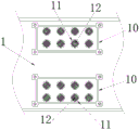
Preferably, the top internal surface intermediate position fixed mounting of the main tank body has the base, and one side external surface fixed mounting of base has motor two, and the output of motor two is towards the bottom of the main tank body, and the output shaft of motor two is provided with the pivot simultaneously, and the pivot all sets up the slope support near the both sides surface of bottom, and the other end and the stoving union coupling of slope support simultaneously, and the output side and the non-woven fabrics body upper surface parallel of stoving pipe correspond, the equidistant through-going of both sides edge of main tank body top surface is provided with the through-hole, and the top surface symmetry of the main tank body is provided with the mounting panel to the inside of mounting panel is provided with the filter screen corresponding with the through-hole.
Adopt above-mentioned technical scheme for the stoving pipe rotates can be even dries the upper surface of non-woven fabrics body.
Preferably, the edge of the upper and lower ends of the feed inlet outside of one side of the main box body is symmetrically provided with a fixing frame, the fixing block is fixedly arranged in the fixing frame, the cavity is formed in the fixing block, the spring is arranged in the cavity, and one end of the spring is embedded in the top end of the cavity.
Adopt above-mentioned technical scheme for thereby the spring can compress and change the distance of scraping off between scraper blade and the lower scraper blade, thereby can scrape off the non-woven fabrics body of different thickness.
Preferably, the other end of spring is connected and is provided with the connecting rod, and the connecting rod sets up to "T" shape to the embedded slip block in top both ends of connecting rod is installed in the lateral wall of the inside cavity of fixed block, and the other end of connecting rod runs through the bottom of fixed block simultaneously, and be flexible sliding connection between fixed block and the connecting rod, be provided with the scraper blade between the connecting rod of main tank feed inlet upper end, and be provided with down the scraper blade between the top of main tank feed inlet lower extreme connecting rod, and placed the non-woven fabrics body between last scraper blade and the lower scraper blade.
Adopt above-mentioned technical scheme for go up the scraper blade and can strike off the inside water of non-woven fabrics body with lower scraper blade and pretreat.
Preferably, a disinfection cavity is formed in the inner wall of one side, close to the discharge end, of the main box body, the non-woven fabric body is arranged in the middle of the disinfection cavity in a communicated mode, and the upper surface and the lower surface, in contact with the non-woven fabric body, of the disinfection cavity are provided with wiping rollers.
Adopt above-mentioned technical scheme for the non-woven fabrics body after can drying disinfects the disinfection, thereby guarantees the cleanliness factor on its surface.
Compared with the prior art, the utility model has the beneficial effects that: the utility model relates to a heating and drying cylinder suitable for a spunlace non-woven fabric production line, which comprises the following components in part by weight:
1. the fan blade I, the fan blade II and the drying pipe are arranged, when the non-woven fabric body is dried, firstly, the wind energy temperature is increased through the rotation of the fan blade I and the fan blade II and then blown to the outer surface of the lower end of the non-woven fabric body, and the outer surface of the upper end of the non-woven fabric body is dried through the rotation of the drying pipe, so that the efficiency of the non-woven fabric body is improved during drying, meanwhile, the drying effect is good, and the drying is comprehensive;
2. the non-woven fabric body is provided with a through hole and a filter screen, water vapor in the main box body is blown out through the top end of the main box body while the fan blades I and II at the bottom end rotate, so that the water vapor is diffused, dust cannot fall into the main box body due to the arrangement of the filter screen in the through hole, a certain filtering effect is achieved, and the cleanliness of the non-woven fabric body is guaranteed;
3. be provided with scraper blade one, scraper blade two and disinfection chamber, can scrape out the inside water of the non-woven fabrics body that gets into through the setting of scraper blade one and scraper blade two to carry out the preliminary treatment, reduce the operating pressure in later stage, can prevent simultaneously that a large amount of water from flowing into the bottom of the main tank body behind the entering main tank body, difficult clearance, inside humidity increases, influences stoving work, and the while is dried and is accomplished the back and pass through the setting of disinfection chamber and wiping roller, carries out the disinfection and isolation processing to the non-woven fabrics body.
Drawings
FIG. 1 is a schematic overall front cross-sectional structural view of the present invention;
FIG. 2 is an enlarged view of the structure at A in FIG. 1 according to the present invention;
FIG. 3 is an enlarged view of the structure at B in FIG. 1 according to the present invention;
FIG. 4 is a schematic top view of the main body of the present invention;
FIG. 5 is a schematic side view of the main housing according to the present invention.
In the figure: 1-main box body, 2-four-corner bracket, 3-motor I, 4-chain wheel, 5-chain, 6-fan I, 7-fan II, 8-mounting rack, 9-electric heating wire, 10-mounting board, 11-through hole, 12-filter screen, 13-base, 14-motor II, 15-rotating shaft, 16-drying tube, 17-guide roller, 18-non-woven fabric body, 19-fixing rack, 20-fixing block, 21-spring, 22-connecting rod, 23-upper scraper, 24-lower scraper, 25-disinfection cavity, 26-wiping roller and 27-universal wheel.
Detailed Description
In order to make the objects, technical solutions and advantages of the present invention more apparent, the present invention is described in further detail below with reference to the accompanying drawings and embodiments. It should be understood that the specific embodiments described herein are merely illustrative of the utility model and are not intended to limit the utility model.
Referring to fig. 1-5, the present invention provides a technical solution of a heating drying cylinder suitable for a spunlace nonwoven fabric production line: a heating drying cylinder suitable for a spunlace non-woven fabric production line comprises a main box body 1, a four-corner support 2, a first motor 3, a chain wheel 4, a chain 5, a first fan blade 6, a second fan blade 7, a mounting rack 8, an electric heating wire 9, a mounting plate 10, a through hole 11, a filter screen 12, a base 13, a second motor 14, a rotating shaft 15, a drying pipe 16, a guide roller 17, a non-woven fabric body 18, a fixing rack 19, a fixing block 20, a spring 21, a connecting rod 22, an upper scraper 23, a lower scraper 24, a disinfection cavity 25, a wiping roller 26 and a universal wheel 27;
in the present embodiment, the outer surface of the bottom end of the main box body 1 is provided with universal wheels 27, the outer surface of the bottom end of the main box body 1 is provided with a four-corner bracket 2 near the middle position, a first motor 3 is fixedly arranged inside the bottom end of the four-corner bracket 2, a first fan blade 6 and a second fan blade 7 are symmetrically arranged at the middle position inside the bottom end of the main box body 1, a drying pipe 16 is symmetrically arranged inside the main box body 1, the drying pipe 16 is arranged obliquely, guide rollers 17 are arranged in the main box body 1 at equal intervals, two ends of each guide roller 17 are rotatably connected with the side wall of the main box body 1, and the outer surface of the guide roller 17 is stuck with a non-woven fabric body 18, and one end of the non-woven fabric body 18 enters from a feed inlet at one side of the main box body 1, the other end of the non-woven fabric body 18 is led out from the discharge hole at the other side of the main box body 1, and the non-woven fabric body 18 forms a V shape in the main box body 1;
further, an output shaft of the motor I3 penetrates through the outer surface of the bottom end of the main box body 1 to be connected with the fan blade I6, a chain wheel 4 is arranged on the outer surface of the output shaft of the motor I3 between the outer surface of the bottom end of the main box body 1 and the bottom end of the four-corner bracket 2, a rotating shaft of the fan blade II 7 penetrates through the outer portion of the bottom end of the main box body 1, the penetrating end of the rotating shaft of the fan blade II 7 is connected with the chain wheel 4, and a chain 5 is arranged between the chain wheel 4 and the chain wheel 4 of the output shaft of the motor I3; the output ends of the first fan blade 6 and the second fan blade 7 face the top end of the main box body 1, the outer surfaces of the output ends of the first fan blade 6 and the second fan blade 7 are transversely provided with an installation frame 8, heating wires 9 are uniformly laid in the installation frame 8, firstly, the first motor 3 is started, an output shaft of the first motor 3 rotates, meanwhile, the first fan blade 6 and the second fan blade 7 rotate simultaneously through the matching between the chain wheel 4 and the chain 5, wind energy is generated and blown to the inside of the main box body 1, then the heating wires 9 in the inside conduct electricity to generate heat, so that the wind blown by the first fan blade 6 and the second fan blade 7 is heated and blown to the bottom end of the non-woven fabric body 18, the non-woven fabric body 18 is dried, and meanwhile, the wind energy can blow the non-woven fabric body 18 to shake, and the drying efficiency is improved;
in the present embodiment, the outer surface of the bottom end of the main box body 1 is provided with universal wheels 27, the outer surface of the bottom end of the main box body 1 is provided with a four-corner bracket 2 near the middle position, a first motor 3 is fixedly arranged inside the bottom end of the four-corner bracket 2, a first fan blade 6 and a second fan blade 7 are symmetrically arranged at the middle position inside the bottom end of the main box body 1, a drying pipe 16 is symmetrically arranged inside the main box body 1, the drying pipe 16 is arranged obliquely, guide rollers 17 are arranged in the main box body 1 at equal intervals, two ends of each guide roller 17 are rotatably connected with the side wall of the main box body 1, and the outer surface of the guide roller 17 is stuck with a non-woven fabric body 18, and one end of the non-woven fabric body 18 enters from a feed inlet at one side of the main box body 1, the other end of the non-woven fabric body 18 is led out from the discharge hole at the other side of the main box body 1, and the non-woven fabric body 18 forms a V shape in the main box body 1;
further, a base 13 is fixedly installed at the middle position of the inner surface of the top end of the main box body 1, a second motor 14 is fixedly installed on the outer surface of one side of the base 13, the output end of the second motor 14 faces the bottom end of the main box body 1, a rotating shaft 15 is connected to the output shaft of the second motor 14, inclined supports are arranged on the outer surfaces of two sides, close to the bottom end, of the rotating shaft 15, the other ends of the inclined supports are connected with a drying pipe 16, the output side of the drying pipe 16 is parallel and corresponds to the upper surface of the non-woven fabric body 18, through holes 11 are formed in the edges of two sides of the outer surface of the top end of the main box body 1 in a penetrating and conducting mode at equal intervals, mounting plates 10 are symmetrically arranged on the outer surface of the top end of the main box body 1, filter screens 12 corresponding to the through holes 11 are arranged inside the mounting plates 10, when the outer surfaces of two sides of the upper end of the non-woven fabric body 18 are dried, the second motor 14 is started firstly, the rotating shaft 15 is rotated, so that the drying pipe 16 is driven to rotate between the outer surfaces of the two sides of the upper end of the non-woven fabric body 18, the drying pipe 16 is started to generate heat energy, the outer surfaces of the two sides of the upper end of the non-woven fabric body 18 are dried, and the whole drying efficiency and drying quality are guaranteed;
in the present embodiment, the outer surface of the bottom end of the main box body 1 is provided with universal wheels 27, the outer surface of the bottom end of the main box body 1 is provided with a four-corner bracket 2 near the middle position, a first motor 3 is fixedly arranged inside the bottom end of the four-corner bracket 2, a first fan blade 6 and a second fan blade 7 are symmetrically arranged at the middle position inside the bottom end of the main box body 1, a drying pipe 16 is symmetrically arranged inside the main box body 1, the drying pipe 16 is arranged obliquely, guide rollers 17 are arranged in the main box body 1 at equal intervals, two ends of each guide roller 17 are rotatably connected with the side wall of the main box body 1, and the outer surface of the guide roller 17 is stuck with a non-woven fabric body 18, and one end of the non-woven fabric body 18 enters from a feed inlet at one side of the main box body 1, the other end of the non-woven fabric body 18 is led out from the discharge hole at the other side of the main box body 1, and the non-woven fabric body 18 forms a V shape in the main box body 1;
further, fixing frames 19 are symmetrically arranged at the edges of the upper end and the lower end of the outer side of the feed port on one side of the main box body 1, fixing blocks 20 are fixedly arranged inside the fixing frames 19, a cavity is arranged inside the fixing blocks 20, a spring 21 is arranged inside the cavity, and one end of the spring 21 is embedded inside the top end of the cavity; the other end of the spring 21 is connected and provided with a connecting rod 22, the connecting rod 22 is set to be in a T shape, the two ends of the top end of the connecting rod 22 are embedded in the side wall of the cavity inside the fixed block 20 in a sliding and clamping mode, the other end of the connecting rod 22 penetrates through the bottom end of the fixed block 20, the fixed block 20 is in telescopic sliding connection with the connecting rod 22, an upper scraper 23 is arranged between the connecting rods 22 at the upper end of a feeding hole of the main box body 1, a lower scraper 24 is arranged between the top ends of the connecting rods 22 at the lower end of the feeding hole of the main box body 1, and a non-woven fabric body 18 is placed between the upper scraper 23 and the lower scraper 24; a disinfection cavity 25 is arranged on the inner wall of one side of the main box body 1 close to the discharge end, a non-woven fabric body 18 is arranged in the middle of the disinfection cavity 25 in a conduction way, and the upper and lower surfaces of the sterilizing chamber 25 which are in contact with the non-woven fabric body 18 are provided with wiping rollers 26, when the non-woven fabric body 18 enters from the feed inlet on one side of the main box body 1, firstly, the non-woven fabric body passes through between the upper scraping plate 23 and the lower scraping plate 24, the upper scraping plate 23 and the lower scraping plate 24 are clamped through the arrangement of the spring 21, when the non-woven fabric body 18 is conveyed to the interior of the main box body 1 through the guide roller 17, the moisture in the interior of the non-woven fabric body 18 is squeezed and scraped through the upper scraper 23 and the lower scraper 24, thereby carrying out pretreatment, facilitating later drying, and simultaneously after the non-woven fabric body 18 is dried, the outer surface of the non-woven fabric body 18 is wiped and disinfected by a wiping roller 26 in the middle of the disinfection cavity 25, so that the cleanliness of the non-woven fabric body 18 is ensured.
The working principle and the using process of the utility model are as follows: after the drying device is installed, firstly, in the drying process, water vapor in the main box body 1 is discharged from the through hole 11 at the top end through wind energy flowing upwards from the bottom end, meanwhile, air in the main box body 1 flows, drying work is convenient to carry out, and meanwhile, the filter screen 12 is fixedly installed on the installation plate 10, and cleaning and replacement at the later stage are convenient.
The above description is only for the purpose of illustrating the preferred embodiments of the present invention and is not to be construed as limiting the utility model, and any modifications, equivalents and improvements made within the spirit and principle of the present invention are intended to be included within the scope of the present invention.