Electromagnetic switch of starter
Technical Field
The utility model relates to the field of electromagnetic switches, in particular to an electromagnetic switch of a starter.
Background
The electromagnetic switch is a switch controlled by an electromagnet, namely a combination of the electromagnet and the switch, generates electromagnetic attraction force after an electromagnet coil is electrified, a movable iron core pushes or pulls a switch contact to be closed so as to connect a controlled circuit, the electromagnetic switch is a contactor which is most common in the industrial field, the electromagnetic switch is a control switch on a starter, and the electromagnetic switch has the working principle that the coil generates electromagnetic attraction force after being electrified so as to move the movable iron core, so that on one hand, a transmission meshing mechanism is pulled to enable a pinion of the starter to move forwards to be meshed with a flywheel gear ring of an engine, on the other hand, the switch contact is pushed to be connected so as to enable a direct current motor to be electrified and operated, and therefore, the engine is driven to start.
The existing starter electromagnetic switch has the defects that the contact can not realize effective contact to the maximum extent, so that the heat productivity is high frequently caused when current is transmitted, electric arcs are easily generated when the contact is closed and disconnected, the contact is ablated or adhered, and the service life of the electromagnetic switch is shortened. Accordingly, those skilled in the art have provided a starter electromagnetic switch to solve the problems set forth in the background art described above.
SUMMERY OF THE UTILITY MODEL
The present invention is directed to a starter electromagnetic switch to solve the problems set forth in the background art.
In order to achieve the purpose, the utility model provides the following technical scheme:
the magnetic blow-out device comprises a shell, wherein a magnetic blow-out groove is formed in the inner wall of the shell, a contact groove is formed in the inner wall of the shell, a plurality of identical magnetic rings are fixedly connected to the inner wall of the magnetic blow-out groove, a movable contact rod is placed inside the shell, a movable disc contact is fixedly connected to the bottom end of the movable contact rod, a static contact rod is fixedly connected to the inner bottom wall of the contact groove, and a static disc contact is fixedly connected to the top end of the static contact rod.
As a further scheme of the utility model: the outer surface of the movable contact rod is sleeved with a return spring, the inner wall of the shell is fixedly connected with an attraction coil, the inner wall of the shell is fixedly connected with a holding coil, the inner wall of the shell is clamped with a sealing cover, and the upper surface of the sealing cover is provided with a square opening.
As a still further scheme of the utility model: the outer fixed surface of shell is connected with the integrated shell, the inner wall fixedly connected with of integrated shell starts the post.
As a still further scheme of the utility model: the inner part of the square opening is movably connected with a pressure rod, the bottom end of the pressure rod is fixedly connected with the upper surface of the movable contact rod, and the upper surface of the movable contact rod is contacted with the bottom surface of the closed cover.
As a still further scheme of the utility model: the bottom surface fixedly connected with two fixed columns of shell, every the equal threaded connection of surface of fixed column has the nut.
As a still further scheme of the utility model: the outer surface of each fixing column is fixedly connected with a fastening gasket, the outer surface of each fastening gasket is fixedly connected with the bottom surface of the shell, and the outer surface of each fastening gasket is in contact with the upper surface of the nut.
As a still further scheme of the utility model: the inner wall of the integrated shell is fixedly connected with a motor column and a storage battery column respectively, and the outer surface of the motor column and the outer surface of the storage battery column are both contacted with the bottom surface of the static disc contact.
Compared with the prior art, the utility model has the beneficial effects that:
1. according to the magnetic blow-out groove, the magnetic ring is arranged, so that the effect of quickly extinguishing the arc can be achieved, the problem that the contact is ablated or adhered due to the fact that the arc is not timely extinguished is avoided, the purpose of timely extinguishing the arc and further protecting the contact is achieved, a good arc extinguishing effect is achieved, the magnetic blow-out groove is arranged, the effect of installing the magnetic ring can be achieved, certain electromagnetism can be guided, the problem that the electromagnetic intensity is not enough to extinguish the arc due to too-dispersed electromagnetic force is avoided, and the magnetic blow-out arc of the magnetic ring is favorably realized.
2. According to the utility model, the movable disc contact and the static disc contact are matched, so that the effect of increasing the effective contact surface of the contact can be achieved, the problem of large heating amount of the contact due to small contact surface of the contact is avoided, the purpose that the contact bears larger current and does not adhere is achieved, the movable contact rod and the static contact rod are matched, the effect of connecting the movable disc contact and the static disc contact can be achieved, and the purpose of switching on and off the electromagnetic switch is achieved.
Drawings
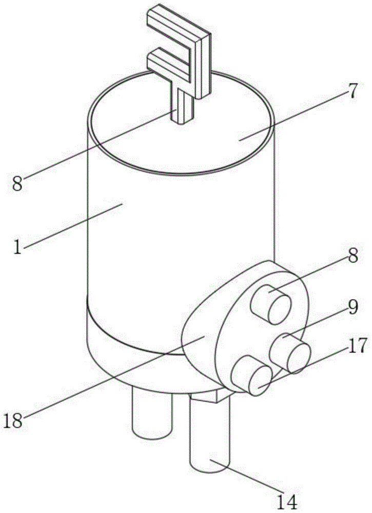
FIG. 1 is a schematic three-dimensional structure of an integrated housing according to the present invention;
FIG. 2 is a cross-sectional view of a front view of a magnetic blow groove of the present invention;
FIG. 3 is a cross-sectional view of a front view of the housing of the present invention;
fig. 4 is a schematic perspective view of the closure of the present invention.
In the figure: 1. a housing; 2. a movable disc contact; 3. a return spring; 4. a closure cap; 5. a pressure lever; 6. a holding coil; 7. an attraction coil; 8. starting the column; 9. a battery post; 10. a movable contact rod; 11. a stationary disc contact; 12. a stationary contact bar; 13. fastening a gasket; 14. fixing a column; 15. a nut; 16. a magnetic ring; 17. a motor column; 18. an integrated shell; 19. magnetic blowing groove; 20. a contact slot; 21. a square opening.
Detailed Description
The technical solutions in the embodiments of the present invention will be clearly and completely described below with reference to the drawings in the embodiments of the present invention, and it is obvious that the described embodiments are only a part of the embodiments of the present invention, and not all of the embodiments. All other embodiments, which can be derived by a person skilled in the art from the embodiments given herein without making any creative effort, shall fall within the protection scope of the present invention.
Referring to fig. 1 to 4, in the embodiment of the present invention, the starter electromagnetic switch includes a housing 1, a magnetic blowing groove 19 is formed on an inner wall of the housing 1, a contact groove 20 is formed on an inner wall of the housing 1, a plurality of identical magnetic rings 16 are fixedly connected to an inner wall of the magnetic blowing groove 19, a movable contact rod 10 is placed inside the housing 1, a movable disk contact 2 is fixedly connected to a bottom end of the movable contact rod 10, a stationary contact rod 12 is fixedly connected to an inner bottom wall of the contact groove 20, and a stationary disk contact 11 is fixedly connected to a top end of the stationary contact rod 12.
Wherein, the outer surface cover of the movable contact rod 10 is equipped with the reset spring 3, through the reset spring 3, can play the effect of resetting, can't separate the problem of the contact while avoiding closing the electromagnetic switch, the inner wall of the outer casing 1 fixedly connects with the attraction coil 7, through the attraction coil 7, can play the role of producing the magnetic field, help the movable contact rod 10 to move, the inner wall of the outer casing 1 fixedly connects with the holding coil 6, through the holding coil 6, can play the role of keeping the contact to connect, avoid loosening the problem that the static disc contact 11 separates from moving disc contact 2 after the pressure lever 5, the inner wall joint of the outer casing 1 has a closing cap 4, through the closing cap 4, can play the role of closing the outer casing 1, avoid the contact to expose and the movable contact rod 10 has no supporting problem, the upper surface of the closing cap 4 has been offered the square mouth 21, through the square mouth 21, can play the role of installing the pressure lever 5, the movable contact type battery charger is beneficial to pressing down the movable contact 2, the outer surface of the shell 1 is fixedly connected with the integrated shell 18, the integrated shell 18 can play a role in integration, the battery post 9, the motor post 17 and the starting post 8 are beneficial to matching, the inner wall of the integrated shell 18 is fixedly connected with the starting post 8, the integrated shell can play a role in receiving a control signal through the starting post 8, the purpose of generating a magnetic field by the attraction coil 7 and the holding coil 6 is achieved, the inner part of the square opening 21 is movably connected with the pressing rod 5, the bottom end of the pressing rod 5 is fixedly connected with the upper surface of the movable contact rod 10, the upper surface of the movable contact rod 10 is in contact with the bottom surface of the sealing cover 4, and the movable contact rod 10 can play a role in pressing through the pressing rod 5, so that the contact connection is facilitated.
Wherein, the bottom surface of the shell 1 is fixedly connected with two fixed columns 14, the function of installing an electromagnetic switch can be achieved through the fixed columns 14, the purpose of fixing the electromagnetic switch and a starter is achieved, the outer surface of each fixed column 14 is in threaded connection with a nut 15, the function of fastening the fixed column 14 can be achieved through the nut 15, the purpose of fixing the fixed column 14 is achieved, the outer surface of each fixed column 14 is fixedly connected with a fastening gasket 13, the function of improving the connection strength can be achieved through the fastening gasket 13, the connection between the nut 15 and the shell 1 is more stable, the outer surface of each fastening gasket 13 is fixedly connected with the bottom surface of the shell 1, the outer surface of each fastening gasket 13 is contacted with the upper surface of the nut 15, the inner wall of the integrated shell 18 is respectively and fixedly connected with a motor column 17 and a battery column 9, the outer surface of the motor column 17 and the outer surface of the battery column 9 are contacted with the bottom surface of the static disc contact 11, through motor post 17 and storage battery post 9, can play the effect of connecting direct current motor and battery, and then realize the purpose for starter power supply.
The working principle of the utility model is as follows: firstly, when needing to use an electromagnetic switch to switch on a circuit of a direct current motor, a shell 1 is arranged on a starter by using a fixed column 14, wherein the winding directions of coils of an attraction coil 7 and a holding coil 6 are opposite, the common intersection point of the attraction coil and the holding coil is connected with the contact point of a starting column 8, the starting column 8 is used for receiving a starting signal of an ignition switch, the other end of the attraction coil 7 is connected with a motor column 17, the motor column 17 is connected with the direct current motor on the starter, the holding coil 6 is connected with the starter, a battery is connected with a battery by using a battery column 9, when the electromagnetic switch is electrified, a movable disc contact 2 is contacted with a static disc contact 11, the circuit is switched on, the holding coil 6 is electrified with the attraction coil 7, the attraction coil 7 and the holding coil 6 can generate a magnetic field, the connected starting column 8 can pass current with the starter, the starter can rotate, and the static disc contact 11 can short-circuit the battery column 9 and the motor column 17, the battery is started by the battery post 9 to supply power to the direct current motor on the starter, so that the starter rotates at a high speed, at the moment, the attraction coil 7 is in short circuit connection, the holding coil 6 enables the electromagnetic switch to continue to work, when the electromagnetic switch is switched off, the current directions in the attraction coil 7 and the holding coil 6 are opposite, magnetic force generated by the coils mutually offsets a part, under the action of the reset spring 3, the movable disc contact 2 is separated from the static disc contact 11, the motor post 17 is not switched on with the battery post 9, and therefore the starter stops rotating.
The above description is only for the preferred embodiment of the present invention, but the scope of the present invention is not limited thereto, and any person skilled in the art should be considered to be within the technical scope of the present invention, and equivalent alternatives or modifications according to the technical solution of the present invention and the inventive concept thereof should be covered by the scope of the present invention.