CN215869228U - Plug-in circuit breaker - Google Patents
Plug-in circuit breaker Download PDFInfo
- Publication number
- CN215869228U CN215869228U CN202121460774.4U CN202121460774U CN215869228U CN 215869228 U CN215869228 U CN 215869228U CN 202121460774 U CN202121460774 U CN 202121460774U CN 215869228 U CN215869228 U CN 215869228U
- Authority
- CN
- China
- Prior art keywords
- circuit breaker
- contact
- pole
- driven
- breaker
- Prior art date
- Legal status (The legal status is an assumption and is not a legal conclusion. Google has not performed a legal analysis and makes no representation as to the accuracy of the status listed.)
- Active
Links
Images


Abstract
The utility model provides an insertion type circuit breaker, includes two at least circuit breaker poles that splice setting side by side, and the both ends of every circuit breaker pole are regarded as first wiring end and second wiring end respectively be equipped with contact mechanism between first wiring end and the second wiring end, contact mechanism is including the moving contact and the static contact of mutually supporting, the moving contact linkage of two at least circuit breaker poles is connected, and one of them circuit breaker pole is as the initiative utmost point, and all the other circuit breaker poles are as the driven utmost point the first wiring end of initiative utmost point is equipped with the operating parts the linkage is connected with operating device between the operating parts and the contact mechanism of initiative utmost point, and when the circuit breaker carries out the divide-shut brake, the moving contact of initiative utmost point is driven by operating device, and the moving contact of driven utmost point is driven by the moving contact of initiative utmost point. According to the utility model, the operating mechanism is only arranged in the active electrode, so that the manufacturing process is simplified, the cost is reduced, meanwhile, larger operating force is not required, and the stability of the circuit breaker is improved.
Description
Technical Field
The utility model relates to a low-voltage apparatus, in particular to a plug-in circuit breaker.
Background
The circuit breaker is a switching device capable of closing, carrying and breaking a current under a normal circuit condition and closing, carrying and breaking a current under an abnormal circuit condition within a prescribed time, and is generally classified into a plug-in type, a fixed type and a drawer type circuit breaker according to its installation manner.
The existing plug-in circuit breaker has the following defects: firstly, a multi-pole circuit breaker is usually formed by splicing a plurality of single-pole circuit breakers, and each circuit breaker pole is provided with an operating mechanism, so that the manufacturing process of the plurality of independent operating mechanisms is complex, the cost is high, the operating force required when the circuit breakers are operated is large, and the reliability of the circuit breakers is reduced; secondly, the breaker does not have the lightning protection module, but the lightning protection module is assembled in the cabinet, so that the assembly and disassembly are difficult, and the replacement of the lightning protection module is not facilitated; thirdly, the circuit breaker is mostly manual operation, does not possess remote operation function, can't satisfy the intelligent requirement of circuit breaker.
Disclosure of Invention
The utility model aims to overcome the defects of the prior art and provides the plug-in circuit breaker which is simple in structure, is provided with a lightning protection module and can realize automatic opening and closing.
In order to achieve the purpose, the utility model adopts the following technical scheme:
the utility model provides an insertion type circuit breaker, includes two at least circuit breaker poles that splice setting side by side, and the both ends of every circuit breaker pole are regarded as first wiring end and second wiring end respectively be equipped with contact mechanism between first wiring end and the second wiring end, contact mechanism is including the moving contact and the static contact of mutually supporting, the moving contact linkage of two at least circuit breaker poles is connected, and one of them circuit breaker pole is as the initiative utmost point, and all the other circuit breaker poles are as the driven utmost point the first wiring end of initiative utmost point is equipped with the operating parts the linkage is connected with operating device between the operating parts and the contact mechanism of initiative utmost point, and when the circuit breaker carries out the divide-shut brake, the moving contact of initiative utmost point is driven by operating device, and the moving contact of driven utmost point is driven by the moving contact of initiative utmost point.
Furthermore, the master control circuit board of the circuit breaker and the electric operation module driven by the master control circuit board are arranged in the active electrode, and the electric operation module is linked with the operating mechanism to enable the circuit breaker to realize automatic opening and closing.
Further, a lightning protection module is also arranged in the breaker pole and connected in the main line of each breaker pole.
Further, still be equipped with arc control device in the circuit breaker utmost point, arc control device is equipped with the lightning protection module including setting up the explosion chamber between contact mechanism and second wiring end between explosion chamber and second wiring end.
Furthermore, one side of the lightning protection module is provided with a second circuit board penetrating through adjacent circuit breaker poles, and the lightning protection module of each circuit breaker pole is electrically connected with the master control circuit board of the circuit breaker through the second circuit board.
And furthermore, a current transformer is further arranged in each circuit breaker pole, a first circuit board penetrating through the adjacent circuit breaker poles is arranged on one side of the current transformer, and the current transformers of the circuit breaker poles are connected with the first circuit board.
Further, an overcurrent protection mechanism is further arranged in the active electrode, the overcurrent protection mechanism comprises a short-circuit protection mechanism and an overload protection mechanism which are respectively arranged on two sides of the operating mechanism, one end of the short-circuit protection mechanism is opposite to the operating mechanism, the movable end of the overload protection mechanism is opposite to the operating mechanism, and the current transformer is arranged between the short-circuit protection mechanism and the contact mechanism.
Furthermore, one of the driven poles is an N-phase breaker pole, a contact mechanism, an arc extinguishing device and a lightning protection module are sequentially arranged between a first wiring end and a second wiring end of the N-phase breaker pole, and a current transformer and an overcurrent protection mechanism are not arranged.
Furthermore, the driven pole comprises at least one L-phase breaker pole and an N-phase breaker pole, and the moving contact of the L-phase breaker pole and the moving contact of the N-phase breaker pole are linked with the moving contact of the driving pole through a linkage shaft.
Furthermore, the contact mechanism comprises a contact support, a moving contact, a fixed contact and a contact spring, the moving contact is arranged on the contact support, the contact spring is arranged between the contact support and the moving contact, the contact support is rotatably arranged in the poles of the circuit breaker, the operating mechanism is connected with the contact support of the active pole, and the moving contacts of two adjacent circuit breaker poles are in linkage connection through the contact supports.
Further, still be equipped with arc control device in every circuit breaker utmost point, contact mechanism still includes insulating barrier, the static contact is fixed in the circuit breaker utmost point and relative with the moving contact, and insulating barrier sets up between the explosion chamber of contact mechanism and arc control device, and establishes in the static contact top, and the moving contact of contact mechanism passes insulating barrier and stretches into the explosion chamber.
Furthermore, the operating mechanism comprises a first connecting rod, a linkage piece, a second connecting rod, a supporting piece, a driving lock catch and a jump buckle, wherein the supporting piece is rotatably assembled in the driving pole, the jump buckle and the driving lock catch are rotatably assembled on the supporting piece, the jump buckle is in hasp fit with one end of the driving lock catch, the linkage piece is rotatably assembled between the supporting piece and the operating piece, the linkage piece is linked with the jump buckle through the first connecting rod, and the supporting piece is connected with the moving contact through the second connecting rod.
Further, a driven lock catch and an overcurrent protection mechanism are arranged in the L-phase circuit breaker pole, the driven lock catch is rotatably assembled and is in linkage connection with a driving lock catch of the operating mechanism, and when the driven pole has an overcurrent fault, the overcurrent protection mechanism drives the driven lock catch to drive the driving lock catch to trigger the operating mechanism to release.
Further, including the shell, separate the installation cavity that forms two at least circuit breaker utmost points in the shell one side of shell is seted up and is strideed across the second mounting groove of two at least installation cavities, and the second circuit board is installed in the second mounting groove, and the second apron lid closes on the second mounting groove.
Further, including the shell, separate the installation cavity that forms two at least circuit breaker utmost points in the shell one side of shell is seted up and is strideed across the first mounting groove of two at least installation cavities, and first circuit board is installed in first mounting groove, and first apron lid closes on first mounting groove.
Further, the operating part is a button mechanism which is linearly arranged at one end of the driving electrode in a sliding mode. According to the plug-in circuit breaker, the operating mechanism is only arranged in the active pole, the contact mechanism of the active pole is directly driven by the operating mechanism, and the contact mechanisms of the other circuit breaker poles are linked with the contact mechanism of the active pole to perform switching-on and switching-off actions, so that the manufacturing process is simplified, the cost is reduced, a large operating force is not required, and the stability of the circuit breaker is improved.
In addition, the lightning protection module is assembled in the circuit breaker, and particularly, the lightning protection module can be assembled through the second mounting groove on one side of the shell, so that the assembly difficulty is simplified, and the disassembly and the assembly of the lightning protection module are facilitated.
In addition, an electric operation module used for driving the circuit breaker to automatically switch on and off is further assembled in the active pole, so that the circuit breaker has a remote operation function, and the intelligent requirement of the circuit breaker is met.
In addition, set up overcurrent protection mechanism and current transformer in the circuit breaker utmost point, improve the sensitivity and the reliability of circuit breaker, set up first mounting groove in one side of shell, make things convenient for the first circuit board of assembly and current transformer connection.
Drawings
Fig. 1 is an external schematic view of a plug-in circuit breaker of the present invention;
fig. 2 is an exploded schematic view of a plug-in circuit breaker of the present invention;
fig. 3 is a schematic structural view of a case in a plug-in type circuit breaker according to the present invention;
fig. 4 is a schematic view of a circuit breaker pole configuration in a plug-in circuit breaker of the present invention;
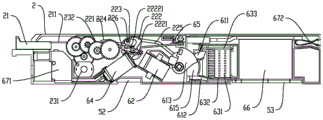
fig. 5 is a schematic structural diagram of an active pole in a plug-in circuit breaker according to the present invention;
fig. 6 is a schematic structural diagram of an active pole of a plug-in circuit breaker (without an electric operating module) according to the present invention;
fig. 7 is a schematic structural diagram of an N-phase circuit breaker pole in a plug-in circuit breaker of the present invention (without a lightning protection module);
fig. 8 is a schematic structural view of an operating mechanism and a movable contact in a plug-in circuit breaker according to the present invention;
fig. 9 is a schematic structural diagram of an operating mechanism and a movable contact in a plug-in circuit breaker according to the present invention;
fig. 10 is a schematic structural view of a contact mechanism in a plug-in circuit breaker according to the present invention;
fig. 11 is a schematic structural diagram of a movable contact in a plug-in circuit breaker according to the present invention.
Detailed Description
The following describes a plug-in circuit breaker according to an embodiment of the present invention with reference to the embodiments shown in fig. 1 to 11. A plug-in type circuit breaker of the present invention is not limited to the description of the following embodiments.
A plug-in circuit breaker comprises a housing 1, wherein a mounting cavity of at least two circuit breaker poles is formed in the housing 1 in a separated mode. At least one partition plate 15 (see fig. 2) is arranged in the housing 1, the housing 1 comprises a first side plate, a second side plate and at least one partition plate 15 arranged between the first side plate and the second side plate, the first side plate, the at least one partition plate 15 and the second side plate are sequentially spliced to divide the housing 1 into mounting cavities of at least two breaker poles, and a breaker pole is assembled in each mounting cavity, so that at least two breaker poles are arranged in the housing 1 in parallel; of course, each circuit breaker pole comprises an independent phase pole housing, two adjacent circuit breaker poles are assembled together through the respective phase pole housings, the housing 1 is composed of a plurality of phase pole housings together, and the inner space of each phase pole housing can be used as an installation cavity. The spliced and assembled structure enables various circuit breakers of two-pole, three-pole or four-pole type to be spliced according to the requirements of users.
A first wiring port and a second wiring port are respectively arranged at two ends of the mounting cavity, as shown in fig. 4-7, a first wiring terminal 671 is arranged at one end of the breaker pole as a first wiring terminal, the first wiring terminal 671 corresponds to the first wiring port, a second wiring terminal 672 is arranged at the other end of the breaker as a second wiring terminal, the second wiring terminal 672 corresponds to the second wiring port, the second wiring port is of a socket structure, and the corresponding second wiring terminal 672 assembled at the second wiring port is a wiring terminal capable of being connected in a plugging manner, so that the breaker can be connected in a plugging manner; be equipped with contact mechanism between the first binding post 671 of every circuit breaker utmost point and second binding post 672, contact mechanism and first binding post 671, second binding post 672 electricity are connected and are used for controlling the break-make of the main line of every circuit breaker utmost point, and the moving contact 611 of two adjacent circuit breaker utmost points links through the universal driving shaft and connects or the one end of the moving contact 611 of all circuit breaker utmost points is structure as an organic whole, is equipped with arc control device between the contact mechanism of every circuit breaker utmost point and second wiring end.
An improvement point of the application lies in that the plug-in circuit breaker includes at least two circuit breaker poles which are spliced in parallel, in two or more circuit breaker poles, one of the circuit breaker poles is used as a driving pole 2, the rest circuit breaker poles are used as a driven pole 3, an operating part 21 and an operating mechanism 22 are only arranged on the driving pole 2, wherein the operating part 21 is arranged at a first terminal of the driving pole 2, the operating part 21 of the embodiment is a button mechanism which is arranged at one end of the driving pole 2 in a linear sliding manner, specifically, an operating part hole for assembling the operating part 21 is arranged at one side of a first wiring port of an installation cavity, the operating mechanism 22 is arranged between the operating part 21 and a contact mechanism, the operating part 21 of the driving pole 2, the operating mechanism 22 and a moving contact 611 of the contact mechanism are sequentially linked and connected, when the circuit breaker is opened and closed, the moving contact 611 of the driving pole 2 is directly driven by the operating mechanism 22, the moving contact 611 of the driven pole 3 is driven by the moving contact 611 of the driving pole 2, so that only one operating mechanism 22 is arranged in the multi-pole circuit breaker, and the manufacturing process is simplified by omitting the operating mechanism 22, so that the cost is reduced, and the operating stability of the circuit breaker is improved. Of course, as another embodiment of the operating member 21, the operating member 21 may be a handle mechanism that is rotatably provided.
Further, still be equipped with the total control circuit board 51 of circuit breaker and by total control circuit board 51 driven electric operator module 23 (refer to fig. 2, 5) in the initiative pole 2, electric operator module 23 is connected with operating device 22 linkage be equipped with microcontroller on the total control circuit board 51, microcontroller can receive, output control signal, make electric operator module 23 drive operating device 22 action to realize the automatic divide-shut brake of circuit breaker, make the circuit breaker have remote control's function. Of course, if the main control circuit board 51 has too many functions, part of the functions can be separated to one sub-control circuit board (not shown), the sub-control circuit board is disposed in the driven electrode 3, and the main control circuit board 51 and the sub-control circuit board are connected together through a circuit board or a wire. Of course, the master control board can also be arranged in the slave pole 3, for example in the N-phase breaker pole 4.
In addition, when the number of the breaker poles is three or more, it is preferable that the driving pole 2 is disposed at a middle position of all the breaker poles, and the operation stability of the breaker is further improved by shortening the linkage time of each pole and reducing the operation force, and when the driven pole 3 includes the N-phase breaker pole 4, it is preferable that the N-phase breaker pole 4 is disposed at a most lateral position, and both the movable contact 611 of the L-phase breaker pole and the movable contact 611 of the N-phase breaker pole 4 are linked with the movable contact 611 of the driving pole 2 through the linking shaft. The L-phase breaker pole is substantially identical in arrangement and layout to the main pole 2, except that the operating mechanism 22 is not provided. The actual active pole 2 is also an L-phase breaker.
As an improvement point of the present application, a lightning protection module 66 (see fig. 3, 5 and 6) is provided in each circuit breaker pole, the lightning protection module 66 is connected in the main line of each circuit breaker pole, preferably, a chamber for assembling the lightning protection module 66 is reserved in the installation cavity, the opening of the chamber is outward, so that the lightning protection module 66 can be assembled to the installation cavity from one side of the housing 1. Further, the chamber used for assembling the lightning protection module 66 in each circuit breaker pole is arranged between the arc extinguishing device and the second wiring end, the openings of all the chambers face to the same side of the shell 1, therefore, the second mounting groove 13 spanning each mounting cavity is formed in one side of the shell 1, after the lightning protection module 66 is assembled, the second mounting groove 13 is covered by the second cover plate 14, the lightning protection module 66 is assembled in the circuit breaker, particularly, the lightning protection module 66 can be assembled and disassembled from one side of the shell 1, and the replacement of the lightning protection module 66 is facilitated. Preferably, the openings of all the chambers are arranged on the upper or lower side of the housing 1 in fig. 1, see fig. 3, the openings of the chambers of the present embodiment are arranged on the lower side, the openings of each circuit breaker pole are arranged side by side, and the installation direction of the lightning protection module 66 is perpendicular to the direction in which the plug-in circuit breaker is inserted into the cabinet. Obviously, the arrangement mode of the lightning protection module in the present application is not only suitable for the embodiment in which the operating mechanism 22 is only arranged on the active pole 2, but also suitable for the embodiment in which each breaker pole is provided with the operating mechanism 22, and is also suitable for the embodiment of breaker poles with other structures.
Preferably, a current transformer 62 (see fig. 5 and 6) is further disposed in each breaker pole, the current transformer 62 is connected to a main line between the contact mechanism and the first connection terminal 671 for collecting a current signal, a first circuit board 52 penetrating through an adjacent breaker pole is disposed at one side of the current transformer 62, the first circuit board 52 is electrically connected to the master control circuit board 51, the current transformers 62 in a plurality of breaker poles are respectively connected to the first circuit board 52 and feed back a current signal to the master control circuit board 51 of the breaker through the first circuit board 52, further, as shown in fig. 3, the first circuit board 52 can be assembled in the mounting cavity from one side of the housing 1, specifically, a first mounting groove 11 crossing each mounting cavity is disposed at one side of the housing 1, and the first mounting groove 11 connects the region of each mounting cavity close to the first connection port, the first circuit board 52 is fitted in the first mounting groove 11 and covered by the first cover plate 12 spanning at least two mounting cavities. It should be noted that the first circuit board 52 can be used not only for connecting the current transformer 62, but also for providing other electrical signals to the general control circuit board 51. Obviously, the arrangement of the current transformer 62 according to the present application is not only applicable to the embodiment in which the operating mechanism 22 is provided only on the active pole 2, but also applicable to the embodiment in which the operating mechanism 22 is provided on each breaker pole, and also applicable to the embodiment of breaker poles having other configurations.
Preferably, still be provided with the hasp piece in all circuit breaker poles, the hasp piece linkage of two adjacent circuit breaker poles is connected, the hasp piece is arranged in first binding post 671 and contact mechanism between the moving contact 611, at this moment, each pole current transformer 62 is preferred to be set up between moving contact 611 and hasp piece, in order to avoid occupying more space, make internal layout more compact, compare the current structure of setting current transformer 62 between second wiring end and arc control device, the overall arrangement of this application does benefit to the length that reduces the circuit breaker, of course, also can not change the length of current circuit breaker, the overall arrangement of adopting this application can leave the space of assembling other function modules between arc control device and second wiring end, set up lightning protection module 66 in this application in this position, do benefit to the miniaturized design of circuit breaker.
Further, an overcurrent protection mechanism is further arranged inside the circuit breaker pole, the overcurrent protection mechanism is located on one side or two sides of the locking piece, positions of the overcurrent protection mechanisms in the driving pole 2 and the driven pole 3 are the same, but the action principle is slightly different, an operating mechanism 22 is arranged in the driving pole 2, the operating mechanism 22 comprises a driving locking piece 222 serving as the locking piece, when a main line of the driving pole 2 is short-circuited and/or has an overload fault, the overcurrent protection mechanism triggers the driving locking piece 222 to enable the operating mechanism 22 to be released, a driven locking piece 31 in linkage connection with the driving locking piece 222 is arranged in the driven pole 3, when the main line of the driven pole 3 is short-circuited and/or has the overload fault, the overcurrent protection mechanism triggers the driven locking piece 31, and the driven locking piece 31 enables the operating mechanism 22 to be released by driving the driving locking piece 22.
The overcurrent protection mechanism comprises a short-circuit protection mechanism 64 and an overload protection mechanism 65, in the active pole 2, the short-circuit protection mechanism 64 and the overload protection mechanism 65 are respectively located at two sides of the active lock catch 222, wherein the short-circuit protection mechanism 64 is preferably arranged obliquely, so that the situation that the horizontally arranged short-circuit protection mechanism 64 needs more action space is avoided, the overload protection mechanism 65 is arranged in parallel with the movable contact 611 along the side of the breaker pole, the width of the movable contact 611 is obviously smaller than that of the arc extinguish chamber 631, the overload protection mechanism 65 is arranged in parallel with the movable contact 611, the width of the breaker pole can be approximately the same as that of the arc extinguish chamber 631, and the whole width of the breaker is favorably reduced.
As shown in fig. 5-6, one end of the short-circuit protection mechanism 64 and the movable end of the overload protection mechanism 65 are opposite to the active latch 222, and trigger the operating mechanism 22 to trip when there is a short-circuit or overload fault in the main line of the active pole 2; referring to fig. 4, in the driven electrode 3, the driven latch 31 is rotatably assembled in the middle of the driven electrode 3, the driven latch 31 is linked with the driving latch 222, the short-circuit protection mechanism 64 and the overload protection mechanism 65 are respectively located at two sides of the driven latch 31, one end of the short-circuit protection mechanism 64 and the movable end of the overload protection mechanism 65 are both opposite to the driven latch 31, the driven latch 31 is triggered when a short-circuit fault or an overload fault exists in a main line of the driven electrode 3, and the driven latch 31 drives the driving latch 222 to release the operating mechanism 22. Preferably, the driven catch 31 may be connected to the driving catch 222 by a shaft (not shown).
An embodiment of a plug-in circuit breaker is provided in connection with fig. 1-11, in this example, the circuit breaker is a four-pole circuit breaker, the housing 1 is divided into four installation cavities by three partitions 15, four circuit breaker poles are respectively arranged in sequence from left to right, and are an a-phase circuit breaker pole, a B-phase circuit breaker pole, a C-phase circuit breaker pole and an N-phase circuit breaker pole 4 in sequence, wherein the B-phase circuit breaker pole is taken as a driving pole 2, and the remaining three circuit breaker poles are taken as driven poles 3. The A-phase breaker pole, the B-phase breaker pole and the C-phase breaker pole are L-phase breaker poles. For convenience of description, in the present embodiment, in the directions of fig. 5 to 7, the direction from the first terminal to the second terminal of the breaker pole is the length direction of the breaker, the direction from the upper side to the lower side of the breaker pole is the height direction of the breaker, and the direction perpendicular to the paper surface is the thickness direction of the breaker.
As shown in fig. 2, 5 and 6, the active pole 2 is mounted in a mounting cavity in the middle of the housing 1, a first terminal 671 and an actuator 21 are provided at a first terminal of the active pole 2, the first terminal 671 and the actuator 21 are respectively located at two sides of the first terminal, and a second terminal 672 of the active pole 2 is provided at a second terminal thereof, wherein the second terminal 672 and the actuator 21 are provided along the same side of the mounting cavity. In this embodiment, the first terminal is an incoming terminal, the first terminal 671 is an incoming terminal, the second terminal is an outgoing terminal, and the second terminal 672 is an outgoing terminal, but the first terminal may also be an outgoing terminal and the second terminal is an incoming terminal, and accordingly, the first terminal 671 is an outgoing terminal and the second terminal 672 is an incoming terminal.
Be equipped with operating device 22, contact mechanism and arc control device between operating parts 21 and second binding post 672, contact mechanism is located the middle part of initiative utmost point 2, and operating device 22 is connected with operating parts 21 linkage, and the moving contact 611 of contact mechanism connects on operating device 22, and the static contact 612 of contact mechanism is fixed in the one side of initiative utmost point 2 and is relative with moving contact 611, static contact 612 is located the both sides of installation cavity respectively with operating parts 21, arc control device includes explosion chamber 631, run-on plate 632 and striking 633, explosion chamber 631 sets up between contact mechanism and second binding post 672, and run-on plate 632 sets up in one side of explosion chamber 631 and is connected with static contact 612, and striking 633 sets up the opposite side and the moving contact 611 electricity at explosion chamber 631.
As shown in fig. 5 and 6, the operating member 21 includes a button and a third link 211 connected to one end of the button, the operating mechanism 22 includes a first link 224, a link 221, a second link 225, a support 223, an active latch 222 and a jump latch 226, the support 223 is rotatably mounted in the active pole 2, the jump latch 226 and the active latch 222 are rotatably mounted on the support 223, the jump latch 226 is snap-fitted to one end of the active latch 222, the other end of the active latch 222 is provided with a first cantilever 2221 and a second cantilever 2222, the first cantilever 2221 and the second cantilever 2222 respectively protrude to both sides, the link 221 is rotatably mounted between the support 223 and the operating member 21, the link 221 is linked with the jump latch 226 through the first link 224, the support 223 is linked with the movable contact 611 through the second link 225, the operating member 21 is linked with the link 221 through the third link 211, for driving the operation mechanism 22.
As shown in fig. 6 and 8-11, the contact mechanism includes a contact support 613, a moving contact 611, a static contact 612, and a contact spring 614, the contact support 613 is rotatably assembled in the mounting cavity, the moving contact 611 is disposed on the contact support 613, the contact spring 614 is disposed between the contact support 613 and the moving contact 611 in a matching manner, the contact support 613 is rotatably mounted in the breaker pole, the operating mechanism is linked with the contact support 613 of the active pole 2 through a second link 225, the operating mechanism drives the moving contact 611 of the active pole 2 through the contact support 613 of the active pole 2, the static contact 612 is fixed on one side of the breaker pole and is opposite to the moving contact 611, and the moving contacts 611 of two adjacent breaker poles are linked and connected through the contact support 613. Preferably, the contact mechanism further includes an insulating baffle 615, the insulating baffle 615 is disposed between the contact mechanism and an arc extinguishing chamber 631 of the arc extinguishing device and above the fixed contact 612, the movable contact 611 of the contact mechanism penetrates through the insulating baffle 615 to extend into one side of the arc extinguishing chamber 631 to be matched with the fixed contact 612, so as to prevent an arc in the arc extinguishing chamber 631 from being reversely sprayed to the contact mechanism, an arc concave surface corresponding to a rotation track of the contact support 613 is formed on one side of the insulating baffle 615 facing the contact support 613, and an arc blocking edge 616 having the same action track as the movable contact 611 is correspondingly protruded on a surface of one side of the insulating baffle 615 facing the arc extinguishing chamber 631.
As shown in fig. 2 and 5, the electric operation module 23 and the master control circuit board 51 of the circuit breaker are stacked in the active electrode 2, and specifically located between the first terminal of the active electrode 2 and the active latch 222, the electric operation module 23 includes a motor 231 and a gear set 232 which are connected in a meshing manner, the motor 231 is connected with the master control circuit board 51, the gear set 232 is connected with the operating mechanism 22 in a linkage manner, a microcontroller for driving the motor 231 to rotate is arranged on the master control circuit board 51, the motor 231 rotates or stops when receiving an action signal, so as to drive the gear set 232 to drive the operating mechanism 22 to perform an opening and closing action, and the number of the gear set 232 can be increased or decreased according to actual situations. In this embodiment, the partition 15 on the side where the main control circuit board 51 is attached is disposed, that is, the main control circuit board 51 is disposed on one side of the thickness direction of the mounting cavity of the active electrode 2 and extends in the length direction between the first mounting groove 11 and the second mounting groove 13, the electric operating module 23 is disposed between the main control circuit board 51 and the active electrode 2, the motor 231 is disposed vertically, that is, disposed perpendicular to the partition 15 and the main control circuit board 51, preferably, the motor 231 is disposed at a position between the first connection terminal 671 and the operating mechanism 22, one side of the gear set 232 stacked on the operating mechanism 21 is matched with the operating mechanism 22, a first-stage gear of the gear set 232 is engaged with the motor 231, a last-stage gear of the gear set 232 is linked with the linking member 221 of the operating mechanism 22, and the operating mechanism 22 is actuated by driving the linking member 221, thereby realizing the automatic opening and closing of the circuit breaker.
As shown in fig. 3, 5 and 6, a current transformer 62 is provided on one side of the operating mechanism 22, the current transformer 62 is connected across the line between the contact arrangement and the first connection for detecting current signals, a first circuit board 52 is arranged at one side of the current transformer 62, a first mounting groove 11 for assembling the first circuit board 52 is arranged at one side of the shell 1, preferably, the first mounting groove 11 spans all mounting cavities, the first circuit board 52 penetrates through one side of all mounting cavities and is connected with a master control circuit board 51 for signal transmission, and is covered by the first cover plate 12 after the assembly is completed, in this embodiment, the first installation groove 11 is located on the same side of the housing 1 as the chamber opening (the opening direction of the second installation groove 13), the side opposite to the operation member 21 is preferably located on the upper side or the lower side of the housing 1 in fig. 1, i.e., a side wall parallel to the thickness direction of the circuit breaker.
An overcurrent protection mechanism is further disposed on two sides of the operating mechanism 22, the overcurrent protection mechanism includes a short-circuit protection mechanism 64 and an overload protection mechanism 65, wherein the short-circuit protection mechanism 64, the current transformer 62 and the fixed contact 612 are disposed on the same side of the installation cavity, the current transformer 62 is obliquely disposed between the active latch 222 and the movable contact 612, the short-circuit protection mechanism 64 is disposed between the first terminal and the active latch 222, and one end of the short-circuit protection mechanism 65 in fig. 5 and 6 is oblique toward the overload protection mechanism 65, so as to avoid that the horizontally disposed short-circuit protection mechanism 64 needs more motion space and increase the width of the circuit breaker, the short-circuit protection mechanism 64 includes a solenoid coil and a movable iron core driven by the solenoid coil, one end of the movable iron core is opposite to the first cantilever 2221 of the active latch 222, and when the active pole 2 has a short-circuit fault, the plunger triggers the first cantilever 2221 to disengage the snap-fit engagement of the active latch 222 with the trip latch 226, thereby disengaging the operating mechanism 22; the overload protection mechanism 65 is disposed on the other side of the installation cavity, that is, the overload protection mechanism 65, the operation element 21 and the arc striking plate 633 are disposed on the same side of the installation cavity, the overload protection mechanism 65 includes a bimetal, a fixed end of the bimetal and the movable contact 611 are disposed in the installation cavity in parallel, a movable end of the bimetal extends towards the first terminal end along the side of the installation cavity, so that the movable end of the bimetal is opposite to the second cantilever 2222 of the active latch 222, when the active pole 2 has an overload fault, the bimetal is heated and bent to trigger the second cantilever 2222, so that the active latch 222 and the trip 226 contact and snap fit, and the operation mechanism 22 is tripped. Of course, the positions of the short-circuit protection mechanism 64 and the overload protection mechanism 65 may be interchanged, that is, the overload protection mechanism 65 and the current transformer 62 are located on the same side of the installation cavity, and the short-circuit protection mechanism 64 is located on the other side of the installation cavity, and in addition, the overcurrent protection mechanism may also be provided with only the short-circuit protection mechanism 64 or the overload protection mechanism 65, or other current protection mechanisms, such as a leakage protection mechanism.
A cavity for assembling the lightning protection module 66 is reserved in the driving electrode 2, the cavity is located between the arc extinguish chamber 631 and the second connection terminal 672, a cavity opening is arranged on one side of the installation cavity, preferably, the cavity of the driving electrode 2 is communicated with the cavity of the adjacent driven electrode 3, a second circuit board 53 is arranged on one side of the lightning protection module 66, the second circuit board 53 is arranged in the shell 1 along the inner side of the cavity opening in a penetrating manner, namely, two ends of the second circuit board 53 extend into the cavity of the adjacent circuit breaker electrode (driven electrode 3), the second circuit board 53 arranged in the penetrating manner is electrically connected with the master control circuit board 51 for signal transmission, the static contact 612 of the driving electrode 2 is electrically connected with the lightning protection module 66 through the arc striking plate 632, the L-phase pin 661 and the N-phase pin 662 of the lightning protection module 66 are respectively connected with the second circuit board 53, so that the lightning protection module 66 is connected into the main circuit of the driving electrode 2 through the second circuit board 53, the lightning protection module 66 is further provided with an auxiliary signal end 663, and the auxiliary signal end 663 is connected with the main control circuit board 51 through the second circuit board 53 to realize signal transmission. In this embodiment, the cavities of all circuit breaker poles are only communicated near the cavity opening, the middle parts of adjacent cavities are still separated from each other by the partition plate 15, thereby the lightning protection modules 66 in all circuit breaker poles are arranged at intervals, the second circuit board 53 is arranged at the same side of all the lightning protection modules 66 along the inner side of the second cover plate 14, therefore, all the lightning protection modules 66 can be connected to the second circuit board 53 at intervals, then the second circuit board 53 connected with the lightning protection modules 66 is assembled in the second installation groove 13 together, at this moment, the lightning protection modules 66 are respectively and correspondingly placed into the driving pole 2 and the cavity of the driven pole 3, the second cover plate 14 covers the circuit breaker poles to keep the shell 1 flat after the assembly is finished, and the dismounting process is simplified.
As shown in fig. 1-2, 4 and 7, the driven pole 3 is assembled in another installation cavity, the driven pole 3 includes a first connection terminal 671, a second connection terminal 672, a contact mechanism, an arc-extinguishing device, a lightning protection module 66 and a current transformer 62 which have the same layout as the driving pole 2, the first connection terminal 671 and the second connection terminal 672 correspond to the first connection port and the second connection port of the installation cavity respectively, the contact mechanism is assembled in the middle of the driven pole 3, the contact mechanism includes a contact support 613, a movable contact 611, a fixed contact 612, a contact spring 614 and an insulating baffle 615, wherein the movable contact 611 is arranged on the contact support 613, the contact support 613 is rotatably assembled in the driven pole 3 and is connected with the driving pole 2 and the contact support 613 in the adjacent driven pole 3 in an interlocking manner, the fixed contact 612 is arranged at one side of the installation cavity, the current transformer 62 is arranged between the contact mechanism and the first connection terminal 671, the operator 21 and the operating mechanism are not provided in the slave electrode 3, but the position of the current transformer 62 is the same as that of the current transformer 62 of the master electrode 2, so that the current transformer 62 is connected to the first circuit board 52 provided through the slave electrode, but the current transformer 62 may not be the same as that of the current transformer 62 of the master electrode 2 as another embodiment in which it is not necessary to connect all the current transformers 62 through one first circuit board 52. The arc extinguishing device sets up between contact mechanism and second binding post 672, reserves the cavity that is used for assembling lightning protection module 66 between arc extinguishing device and second binding post 672, and lightning protection module 66 is connected with the second circuit board 53 that runs through the setting.
An overcurrent protection mechanism can be further arranged in the driven electrode 3, a driven latch 31 (see fig. 4) matched with the overcurrent protection mechanism is assembled in the driven electrode 3, the driven latch 31 is linked with the driving latch 222 and is located at the same position of different installation cavities, preferably, the layout positions of the overcurrent protection mechanism and the driven latch 31 are the same as that of the overcurrent protection mechanism and the driving latch 222 of the driving electrode 2, the driven latch 31 is linked with the driving latch 222, and when an overcurrent fault occurs in the driven electrode 3, such as a short circuit or an overload fault, the overcurrent protection mechanism triggers the driven latch 31, the driven latch 31 drives the driving latch 222 to act, so that the operating mechanism 22 of the driving electrode 2 is tripped, and the circuit breaker is tripped and powered off. By omitting the operating mechanism in the driven pole 3 and only providing one driven latch 31, the structure is simplified and the cost is reduced.
Like the driving pole 2, the current transformer 62 in the driven pole 3 is located between the driven latch 31 and the moving contact 611, that is, the current transformer 62 in the driving pole 2 is located at the same position; the overcurrent protection mechanism comprises a short-circuit protection mechanism 64 and/or an overload protection mechanism 65, the driven latch 31 also comprises a first cantilever and a second cantilever, the short-circuit protection mechanism 64 is arranged on one side of the driven latch 31, a movable iron core of the short-circuit protection mechanism 64 is opposite to the first cantilever, the overload protection mechanism 65 is arranged on the other side of the driven latch 31, a movable end of a bimetallic strip of the overload protection mechanism 65 is opposite to the second cantilever, the driven latch 31 and the driving latch 222 can adopt the same structure, and certainly, as a jump latch 226 is not arranged in the driven pole 3, the other end of the driven latch 31 can omit a structure for forming a snap connection.
Of course, as a simplified structure of the driven electrode 3, the driven electrode 3 may only be provided with the contact mechanism, the arc extinguishing chamber 631 and the lightning protection module 66 which are the same as the driving electrode 2, and no overcurrent protection device, the driven latch 31 and the current transformer 62 are provided, when all the driven electrodes 3 are assembled with the driving electrode 2 by adopting the simplified structure, the first mounting groove 11 may be only provided on one side of the driving electrode 2, or the first mounting groove 11 may be directly omitted, the first circuit board 52 is also provided inside the driving electrode 2, and at this time, the circuit breaker may still implement the function of turning on and off the circuit, but the effect in the aspects of current detection precision and overcurrent protection is relatively poor.
Preferably, the simplified driven pole 3 is used as an N-phase breaker pole 4, as shown in fig. 7, the N-phase breaker pole 4 is a driven pole 3 located at an edge side, the current transformer 62, the overcurrent protection mechanism and the driven latch 31 are not arranged in the N-phase breaker pole 4, the first connection terminal 671, the contact mechanism, the arc extinguishing chamber 631 and the lightning protection module 66 are assembled in the same manner as the other driven poles 3, unlike the other driven poles 3, preferably, the movable contact 611 in the contact mechanism is formed by laminating two or more movable contacts 611, that is, the thickness of the movable contact 611 of the N-phase breaker pole 4 is greater than that of the movable contact 611 of the L-phase breaker pole, at least two second connection terminals 672 connected in parallel are arranged at the first connection terminal of the N-phase breaker pole 4 to increase the current carrying capacity, preferably, two second connection terminals 672 are arranged at the N-phase breaker pole 4, two second binding post 672 are located one side of second wiring end, set up two second wiring mouth that parallel this moment in one side of the second wiring end of installation cavity, are equipped with the third wiring mouth at the opposite side of second wiring end, the third wiring mouth adopts the socket structure be equipped with binding post of a plug connection in the third wiring mouth as PE port 41, lightning protection module 66 and two parallelly connected second binding post 672 in the N looks circuit breaker utmost point 4, PE port 41 is connected, PE port 41 is located the both sides (upside and downside) of second wiring end respectively with second binding post 672.
Preferably, the N-phase circuit breaker pole 4 is arranged in an installation cavity on the most lateral side in the housing 1, a space for assembling the branch control circuit board is reserved inside the N-phase circuit breaker pole 4, the branch control circuit board is assembled in the N-phase circuit breaker pole 4, the branch control circuit board has a functional module which is disassembled by the main control circuit board 51, and the branch control circuit board is preferably connected with the main control circuit board 51 through a first circuit board 52. It should be noted that the main control circuit board and the sub-control circuit board are only distinguished by names and do not represent specific circuit boards, the circuit board disposed in the N-phase circuit breaker pole 4 may also be the main control circuit board, and the circuit board disposed in the active pole 2 may also be the sub-control circuit board.
The foregoing is a more detailed description of the utility model in connection with specific preferred embodiments and it is not intended that the utility model be limited to these specific details. For those skilled in the art to which the utility model pertains, several simple deductions or substitutions can be made without departing from the spirit of the utility model, and all shall be considered as belonging to the protection scope of the utility model.
Claims (16)
1. The utility model provides a plug-in circuit breaker, includes two at least circuit breaker poles that splice setting side by side, and the both ends of every circuit breaker pole are as first wiring end and second wiring end respectively be equipped with contact mechanism between first wiring end and the second wiring end, contact mechanism includes moving contact (611) and static contact (612) of mutually supporting, its characterized in that: moving contacts (611) of at least two circuit breaker poles are in linkage connection, one circuit breaker pole is used as a driving pole (2), the other circuit breaker poles are used as driven poles (3), an operating part (21) is arranged at a first terminal of the driving pole (2), an operating mechanism (22) is in linkage connection between the operating part (21) and a contact mechanism of the driving pole (2), when the circuit breaker is switched on and switched off, the moving contact (611) of the driving pole (2) is driven by the operating mechanism (22), and the moving contact (611) of the driven pole (3) is driven by the moving contact (611) of the driving pole (2).
2. A plug-in circuit breaker as claimed in claim 1, characterized in that: the master control circuit board (51) of the circuit breaker and the electric operation module (23) driven by the master control circuit board (51) are arranged in the active electrode (2), and the electric operation module (23) is linked with the operating mechanism (22) to enable the circuit breaker to realize automatic opening and closing.
3. A plug-in circuit breaker as claimed in claim 1, characterized in that: also arranged within the breaker poles is a lightning protection module (66), said lightning protection module (66) being connected in the main line of each breaker pole.
4. A plug-in circuit breaker as claimed in claim 3, characterized in that: still be equipped with arc control device in the circuit breaker utmost point, arc control device is equipped with lightning protection module (66) including setting up explosion chamber (631) between contact mechanism and second wiring end between explosion chamber (631) and second wiring end.
5. A plug-in circuit breaker as claimed in claim 3, characterized in that: one side of the lightning protection module (66) is provided with a second circuit board (53) which penetrates through the adjacent circuit breaker poles, and the lightning protection module (66) of each circuit breaker pole is electrically connected with a master control circuit board (51) of the circuit breaker through the second circuit board (53).
6. A plug-in circuit breaker as claimed in claim 1, characterized in that: still be equipped with current transformer (62) in the circuit breaker utmost point, be equipped with first circuit board (52) that run through adjacent circuit breaker utmost point in one side of current transformer (62), current transformer (62) of each circuit breaker utmost point all are connected with first circuit board (52).
7. A plug-in circuit breaker as claimed in claim 6, characterized in that: still be equipped with overcurrent protection mechanism in the initiative utmost point (2), overcurrent protection mechanism is including setting up short-circuit protection mechanism (64) and overload protection mechanism (65) in operating device (22) both sides respectively, and the one end of short-circuit protection mechanism (64) is relative with operating device (22), and the active end of overload protection mechanism (65) is relative with operating device (22), current transformer (62) set up between short-circuit protection mechanism (64) and contact mechanism.
8. A plug-in circuit breaker according to any one of claims 1 to 7, characterized in that: one of them driven pole (3) is N looks circuit breaker utmost point (4) set gradually contact mechanism, arc extinguishing device and lightning protection module (66) between the first wiring end of N looks circuit breaker utmost point (4) and the second wiring end, do not set up current transformer (62) and overcurrent protection mechanism.
9. A plug-in circuit breaker as claimed in claim 1, characterized in that: the driven pole (3) comprises at least one L-phase breaker pole and an N-phase breaker pole (4), and a moving contact (611) of the L-phase breaker pole and a moving contact (611) of the N-phase breaker pole (4) are linked with the moving contact (611) of the driving pole (2) through a linkage shaft.
10. A plug-in circuit breaker as claimed in claim 1, characterized in that: the contact mechanism comprises a contact support (613), a moving contact (611), a fixed contact (612) and a contact spring (614), the moving contact (611) is arranged on the contact support (613), the contact spring (614) is arranged between the contact support (613) and the moving contact (611), the contact support (613) is rotatably arranged in a breaker pole, the operating mechanism (22) is connected with the contact support (613) of the active pole (2), and the moving contacts (611) of two adjacent breaker poles are connected in a linkage mode through the contact support (613).
11. A plug-in circuit breaker as claimed in claim 10, characterized in that: still be equipped with arc control device in every circuit breaker utmost point, contact mechanism still includes insulating baffle (615), static contact (612) are fixed in the circuit breaker utmost point and relative with moving contact (611), and insulating baffle (615) set up between contact mechanism and arc control device's explosion chamber (631), and establish above static contact (612), and moving contact (611) of contact mechanism pass insulating baffle (615) and stretch into explosion chamber (631).
12. A plug-in circuit breaker as claimed in claim 1, characterized in that: the operating mechanism (22) comprises a first connecting rod (224), a linkage piece (221), a second connecting rod (225), a supporting piece (223), an active lock catch (222) and a jump buckle (226), wherein the supporting piece (223) is rotatably assembled in the active pole (2), the jump buckle (226) and the active lock catch (222) are rotatably assembled on the supporting piece (223), the jump buckle (226) is in snap-fit with one end of the active lock catch (222), the linkage piece (221) is rotatably assembled between the supporting piece (223) and the operating piece (21), the linkage piece (221) is in linkage with the jump buckle (226) through the first connecting rod (224), and the supporting piece (223) is connected with the movable contact (611) through the second connecting rod (225).
13. A plug-in circuit breaker as claimed in claim 9, characterized in that: be equipped with driven hasp (31) and overcurrent protection mechanism in L looks circuit breaker utmost point, driven hasp (31) rotate the assembly and be connected with initiative hasp (222) linkage of operating device (22), when overcurrent trouble takes place for driven utmost point (3), overcurrent protection mechanism drive driven hasp (31) drive initiative hasp (222), trigger operating device (22) and trip.
14. A plug-in circuit breaker as claimed in claim 5, characterized in that: including shell (1), separate the installation cavity that forms two at least circuit breaker utmost points in shell (1) second mounting groove (13) of strideing across two at least installation cavities are seted up to one side of shell (1), and second circuit board (53) are installed in second mounting groove (13), and second apron (14) lid closes on second mounting groove (13).
15. A plug-in circuit breaker as claimed in claim 6, characterized in that: including shell (1), separate the installation cavity that forms two at least circuit breaker utmost points in shell (1) first mounting groove (11) of strideing across two at least installation cavities are seted up to one side of shell (1), and first circuit board (52) are installed in first mounting groove (11), and first apron (12) lid closes on first mounting groove (11).
16. A plug-in circuit breaker as claimed in claim 1, characterized in that: the operating piece (21) is a button mechanism which is linearly arranged at one end of the active electrode (2) in a sliding manner.
Priority Applications (1)
| Application Number | Priority Date | Filing Date | Title |
|---|---|---|---|
| CN202121460774.4U CN215869228U (en) | 2021-06-29 | 2021-06-29 | Plug-in circuit breaker |
Applications Claiming Priority (1)
| Application Number | Priority Date | Filing Date | Title |
|---|---|---|---|
| CN202121460774.4U CN215869228U (en) | 2021-06-29 | 2021-06-29 | Plug-in circuit breaker |
Publications (1)
| Publication Number | Publication Date |
|---|---|
| CN215869228U true CN215869228U (en) | 2022-02-18 |
Family
ID=80335459
Family Applications (1)
| Application Number | Title | Priority Date | Filing Date |
|---|---|---|---|
| CN202121460774.4U Active CN215869228U (en) | 2021-06-29 | 2021-06-29 | Plug-in circuit breaker |
Country Status (1)
| Country | Link |
|---|---|
| CN (1) | CN215869228U (en) |
-
2021
- 2021-06-29 CN CN202121460774.4U patent/CN215869228U/en active Active
Similar Documents
| Publication | Publication Date | Title |
|---|---|---|
| WO2016008297A1 (en) | Low-voltage circuit breaker with residual current tripping device | |
| CN217061971U (en) | Circuit breaker | |
| CN215869228U (en) | Plug-in circuit breaker | |
| CN215869227U (en) | Plug-in circuit breaker | |
| CN215869211U (en) | Plug-in circuit breaker | |
| CN215869249U (en) | Plug-in circuit breaker | |
| CN215869173U (en) | Shell structure of plug-in circuit breaker | |
| CN215869172U (en) | Plug-in circuit breaker | |
| CN215869210U (en) | Plug-in circuit breaker | |
| CN217061947U (en) | Circuit breaker | |
| CN217061989U (en) | Circuit breaker | |
| CN212695091U (en) | Compact reclosing circuit breaker | |
| CN115547769A (en) | Plug-in circuit breaker | |
| CN215869174U (en) | Plug-in circuit breaker | |
| CN215869238U (en) | Circuit breaker | |
| CN215869254U (en) | Circuit breaker | |
| CN215869241U (en) | Circuit breaker | |
| CN111900043A (en) | Circuit breaker | |
| CN214505400U (en) | Small-sized circuit breaker | |
| CN214956668U (en) | Small-sized circuit breaker | |
| CN217444317U (en) | Circuit breaker | |
| CN214505410U (en) | Small-sized circuit breaker | |
| CN115547762A (en) | Plug-in circuit breaker | |
| CN214505409U (en) | Small-sized circuit breaker | |
| CN219370926U (en) | Circuit breaker accessory and circuit breaker |
Legal Events
| Date | Code | Title | Description |
|---|---|---|---|
| GR01 | Patent grant | ||
| GR01 | Patent grant |