CN215843658U - Luminous water outlet device, pull-type luminous faucet and luminous spring faucet - Google Patents
Luminous water outlet device, pull-type luminous faucet and luminous spring faucet Download PDFInfo
- Publication number
- CN215843658U CN215843658U CN202121506280.5U CN202121506280U CN215843658U CN 215843658 U CN215843658 U CN 215843658U CN 202121506280 U CN202121506280 U CN 202121506280U CN 215843658 U CN215843658 U CN 215843658U
- Authority
- CN
- China
- Prior art keywords
- water
- water outlet
- cavity
- luminous
- side wall
- Prior art date
- Legal status (The legal status is an assumption and is not a legal conclusion. Google has not performed a legal analysis and makes no representation as to the accuracy of the status listed.)
- Active
Links
Images


Classifications
-
- E—FIXED CONSTRUCTIONS
- E03—WATER SUPPLY; SEWERAGE
- E03C—DOMESTIC PLUMBING INSTALLATIONS FOR FRESH WATER OR WASTE WATER; SINKS
- E03C1/00—Domestic plumbing installations for fresh water or waste water; Sinks
- E03C1/02—Plumbing installations for fresh water
- E03C1/04—Water-basin installations specially adapted to wash-basins or baths
- E03C1/0404—Constructional or functional features of the spout
-
- F—MECHANICAL ENGINEERING; LIGHTING; HEATING; WEAPONS; BLASTING
- F21—LIGHTING
- F21S—NON-PORTABLE LIGHTING DEVICES; SYSTEMS THEREOF; VEHICLE LIGHTING DEVICES SPECIALLY ADAPTED FOR VEHICLE EXTERIORS
- F21S9/00—Lighting devices with a built-in power supply; Systems employing lighting devices with a built-in power supply
- F21S9/04—Lighting devices with a built-in power supply; Systems employing lighting devices with a built-in power supply the power supply being a generator
- F21S9/046—Lighting devices with a built-in power supply; Systems employing lighting devices with a built-in power supply the power supply being a generator driven by hydropower, e.g. by water powered turbines
-
- F—MECHANICAL ENGINEERING; LIGHTING; HEATING; WEAPONS; BLASTING
- F21—LIGHTING
- F21V—FUNCTIONAL FEATURES OR DETAILS OF LIGHTING DEVICES OR SYSTEMS THEREOF; STRUCTURAL COMBINATIONS OF LIGHTING DEVICES WITH OTHER ARTICLES, NOT OTHERWISE PROVIDED FOR
- F21V33/00—Structural combinations of lighting devices with other articles, not otherwise provided for
- F21V33/0004—Personal or domestic articles
- F21V33/004—Sanitary equipment, e.g. mirrors, showers, toilet seats or paper dispensers
-
- E—FIXED CONSTRUCTIONS
- E03—WATER SUPPLY; SEWERAGE
- E03C—DOMESTIC PLUMBING INSTALLATIONS FOR FRESH WATER OR WASTE WATER; SINKS
- E03C1/00—Domestic plumbing installations for fresh water or waste water; Sinks
- E03C1/02—Plumbing installations for fresh water
- E03C1/04—Water-basin installations specially adapted to wash-basins or baths
- E03C2001/0418—Water-basin installations specially adapted to wash-basins or baths having temperature indicating means
-
- F—MECHANICAL ENGINEERING; LIGHTING; HEATING; WEAPONS; BLASTING
- F21—LIGHTING
- F21Y—INDEXING SCHEME ASSOCIATED WITH SUBCLASSES F21K, F21L, F21S and F21V, RELATING TO THE FORM OR THE KIND OF THE LIGHT SOURCES OR OF THE COLOUR OF THE LIGHT EMITTED
- F21Y2103/00—Elongate light sources, e.g. fluorescent tubes
- F21Y2103/30—Elongate light sources, e.g. fluorescent tubes curved
- F21Y2103/33—Elongate light sources, e.g. fluorescent tubes curved annular
-
- F—MECHANICAL ENGINEERING; LIGHTING; HEATING; WEAPONS; BLASTING
- F21—LIGHTING
- F21Y—INDEXING SCHEME ASSOCIATED WITH SUBCLASSES F21K, F21L, F21S and F21V, RELATING TO THE FORM OR THE KIND OF THE LIGHT SOURCES OR OF THE COLOUR OF THE LIGHT EMITTED
- F21Y2115/00—Light-generating elements of semiconductor light sources
- F21Y2115/10—Light-emitting diodes [LED]
-
- Y—GENERAL TAGGING OF NEW TECHNOLOGICAL DEVELOPMENTS; GENERAL TAGGING OF CROSS-SECTIONAL TECHNOLOGIES SPANNING OVER SEVERAL SECTIONS OF THE IPC; TECHNICAL SUBJECTS COVERED BY FORMER USPC CROSS-REFERENCE ART COLLECTIONS [XRACs] AND DIGESTS
- Y02—TECHNOLOGIES OR APPLICATIONS FOR MITIGATION OR ADAPTATION AGAINST CLIMATE CHANGE
- Y02E—REDUCTION OF GREENHOUSE GAS [GHG] EMISSIONS, RELATED TO ENERGY GENERATION, TRANSMISSION OR DISTRIBUTION
- Y02E10/00—Energy generation through renewable energy sources
- Y02E10/20—Hydro energy
-
- Y—GENERAL TAGGING OF NEW TECHNOLOGICAL DEVELOPMENTS; GENERAL TAGGING OF CROSS-SECTIONAL TECHNOLOGIES SPANNING OVER SEVERAL SECTIONS OF THE IPC; TECHNICAL SUBJECTS COVERED BY FORMER USPC CROSS-REFERENCE ART COLLECTIONS [XRACs] AND DIGESTS
- Y10—TECHNICAL SUBJECTS COVERED BY FORMER USPC
- Y10T—TECHNICAL SUBJECTS COVERED BY FORMER US CLASSIFICATION
- Y10T137/00—Fluid handling
- Y10T137/9464—Faucets and spouts
Abstract
The utility model discloses a luminous water outlet device which comprises a hydroelectric generation module, a water distribution body, a waterway switching module, a water outlet panel and a luminous lamp panel. The hydroelectric generation module sets up in water inlet department, divide the water body to have two water routes, water route switching module is used for switching rivers and is in circulation in the two water routes, the play water panel corresponds the setting and is in two water routes below, luminous lamp plate with hydroelectric generation module electricity is connected. Compared with the prior art, the hydroelectric generation module is arranged at the water inlet end, so that the light-emitting lamp panel can emit light no matter which waterway the water flows out. The installation is simple, and the structure space demand is less, and waterway structure is simple.
Description
Technical Field
The utility model relates to the technical field of sanitary wares, in particular to a luminous water outlet device.
Background
Faucets or showers are very frequently used products in daily life. In order to meet the use requirements of users in different application scenes and improve the user experience, some water faucets which utilize water flow to generate electricity as a light-emitting power supply and simultaneously realize the functions of energy conservation, illumination and the like appear on the market at present. However, in the existing faucet with the light-emitting function, the hydroelectric power generation device is often arranged near the lower end and the water outlet of the faucet, the light-emitting function can be realized only when a part of water paths are communicated, and the effect that all the water paths are communicated and can emit light cannot be realized. In addition, because the power generation device and the light-emitting device are additionally arranged at the water outlet end of the faucet, the design space of a water path at the water outlet end is extruded, the production and assembly difficulty is increased, and the overall appearance of the faucet looks too fat and is not beneficial.
SUMMERY OF THE UTILITY MODEL
The utility model aims to overcome the defects of the prior art and provides a luminous water outlet device.
In order to achieve the purpose, the utility model provides the following technical scheme:
a luminous water outlet device comprises a hydroelectric generation module, a water distribution body, a waterway switching module, a water outlet panel and a luminous lamp panel,
the hydroelectric generation module sets up in water inlet department, divide the water body to have two water routes, water route switching module is used for switching rivers and is in circulation in the two water routes, the play water panel corresponds the setting and is in two water routes below, luminous lamp plate with hydroelectric generation module electricity is connected.
Furthermore, the luminous water outlet device further comprises a connecting piece, the water diversion body comprises an upper connecting portion, a water diversion cavity and a lower connecting portion, one end of the connecting piece is a water inlet, the other end of the connecting piece is connected with the upper connecting portion, and the hydroelectric generation module is arranged in a cavity formed by the connecting piece and the upper connecting portion together.
Furthermore, hydroelectric power generation module is including the impeller cavity that is used for holding the impeller and the motor cavity that is used for holding the generator, impeller central shaft connects motor shaft, the impeller cavity upper end is sealed, and the slant water inlet is seted up to the side, and rivers flow in follow behind the impeller cavity the water hole of crossing of motor cavity upper end both sides is followed motor cavity lateral wall with the connecting piece lateral wall with the clearance between the upper junction lateral wall flows out, and is in from setting up the water hole of crossing of upper junction bottom surface flows in divide the water cavity.
Furthermore, external button is connected to water route switching module one end, and the other end set up in the water diversion cavity, through pressing the button makes water route switching module lateral shifting switches rivers and is in divide the circulation in the water route.
Furthermore, the bottom surface of connecting portion still is provided with wiring hole one on dividing the water, the lead-out wire of motor is followed wiring hole one is drawn out, the upper wall of connecting portion is provided with wiring hole two under the water of branch, the lead-out wire of motor passes through wiring hole two with the luminescent lamp plate is connected, all overlap in wiring hole one and the wiring hole two and establish waterproof silica gel cover.
Further, the water diversion cavity comprises a middle water path, a right side water path and a communicating cavity body, the middle water path and the right side water path are arranged in the cavity body, the water path switching module comprises a hollow cylindrical sealing block, a sliding rod and a fixed rod, one end of the hollow cylindrical sealing block is closed, one end of the hollow cylindrical sealing block is open, the sliding rod and the fixed rod are arranged in the cavity body, the sealing block is sealed outwards and communicated with the cavity body, the middle water path and the right side water path are arranged in the cavity body, one end of the sliding rod is connected with the button, the other end of the sliding rod is located, the sealing block is sealed inwards, and the fixed rod is matched with the side wall of the cavity body in a sliding mode to achieve transverse movement.
Further, the slide bar is located the inboard one end of shutoff piece blind end is equipped with the slip jaw, slip jaw outer wall sets up first sealing member, shutoff piece blind end inboard sets up the second sealing member, first sealing member, second sealing member with the sealed cooperation of shutoff piece, the slide bar moves left and makes the slip jaw with the dead lever separation, first sealing member will the end that opens of shutoff piece is sealed, simultaneously the right side water route is unblocked, the slide bar moves right and makes the dead lever inserts in the slip jaw, first sealing member moves thereupon and seals right side water route entry, and the middle part water route is unblocked simultaneously, and rivers warp the shutoff piece is located the through-hole on the lateral wall between first sealing member and the second sealing member flows.
Further, divide the lower connecting portion of water to include middle part delivery port and peripheral delivery port, middle part delivery port intercommunication the middle part water route, peripheral delivery port intercommunication the right side water route, the surface of water board is the printing opacity material, and its play water is the arc concavity, its inboard middle part be equipped with the retaining ring that middle part delivery port lateral wall matches, peripheral delivery port lateral wall with the cooperation of the quick-connect of surface of water board lateral wall, the retaining ring with middle part delivery port lateral wall gomphosis, luminous lamp plate set up in divide the upper wall of connecting portion under the water, and be located between the lateral wall of middle part delivery port and peripheral delivery port.
According to another aspect of the utility model, a pull-out faucet is provided, which comprises the luminous water outlet device.
According to a further aspect of the utility model, there is provided a lighted spring faucet that includes a lighted tap device as described above.
The utility model has the beneficial effects that:
the hydroelectric generation module is arranged at the water inlet end, so that the light-emitting lamp panel can emit light no matter which waterway discharges water. The installation is simple, and the structure space demand is less, and waterway structure is simple.
Drawings
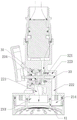
Fig. 1 is an exploded view of a light-emitting water outlet device according to an embodiment of the present invention.
Fig. 2 is a cross-sectional view of a light-emitting water outlet device according to an embodiment of the present invention, which shows a state of a right waterway being conducted.
Fig. 3 is a cross-sectional view of a light-emitting water outlet device according to an embodiment of the utility model, which shows a state of a middle water path being conducted.
FIG. 4 is a top view of an impeller cavity of a light-emitting water outlet device in accordance with an embodiment of the present invention.
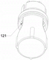
Fig. 5 is a perspective view of a hydroelectric power generation module of a light-emitting water outlet device according to an embodiment of the present invention.
Fig. 6 is a cross-sectional view of a hydroelectric power generation module of a light-emitting water outlet apparatus according to an embodiment of the present invention.
Fig. 7 is a cross-sectional view of a light-emitting water outlet device according to another embodiment of the utility model.
Fig. 8 is an assembly view of a luminous water outlet device according to another embodiment of the present invention.
Description of reference numerals: 1-a hydroelectric generation module, 11-an impeller cavity, 110-an inclined water inlet, 12-a motor cavity, 121-a water passing hole, 2-a water dividing body, 21-an upper connecting part, 212-a wiring hole I, 211-a water passing hole, 22-a water dividing cavity, 221-a middle water channel, 222-a right water channel, 223-a cavity, 23-a lower connecting part, 231-a wiring hole II, 232-a waterproof silica gel sleeve, 233-a middle water outlet, 234-a peripheral water outlet, 3-a water channel switching module, 31-a blocking block, 32-a sliding rod, 321-a sliding fork head, 322-a first sealing piece, 323-a second sealing piece, 324-a limiting block, 33-a fixing rod, 4-a water outlet panel, 41-a retaining ring and 5-a light-emitting lamp panel, 51-light guide plate, 6-connecting piece, 61-water inlet, 7-button.
The implementation, functional features and advantages of the objects of the present invention will be further explained with reference to the accompanying drawings.
Detailed Description
In order to make the objects, technical solutions and advantages of the embodiments of the present invention more apparent, the technical solutions of the embodiments of the present invention will be described clearly and completely with reference to the accompanying drawings of the embodiments of the present invention, and it is obvious that the described embodiments are some, but not all embodiments of the present invention. All other embodiments, which can be obtained by a person skilled in the art without any inventive step based on the embodiments of the present invention, are within the scope of the present invention. Thus, the following detailed description of the embodiments of the present invention, presented in the figures, is not intended to limit the scope of the utility model, as claimed, but is merely representative of selected embodiments of the utility model. All other embodiments, which can be obtained by a person skilled in the art without any inventive step based on the embodiments of the present invention, are within the scope of the present invention.
In the description of the present invention, it should be noted that the terms "upper", "lower", "inner", "outer", "front", "rear", "both ends", "one end", "the other end", "one face", "the other face", and the like indicate orientations or positional relationships based on the orientations or positional relationships shown in the drawings, and are only for convenience of describing the present invention and simplifying the description, but do not indicate or imply that the device or element referred to must have a specific orientation, be constructed in a specific orientation, and be operated, and thus, should not be construed as limiting the present invention. Furthermore, the terms "first" and "second" are used for descriptive purposes only and are not to be construed as indicating or implying relative importance.
In the description of the present invention, it is to be noted that, unless otherwise explicitly specified or limited, the terms "disposed", "connected", and the like are to be construed broadly, such as "connected", may be fixedly connected, or detachably connected or integrally connected; can be mechanically or electrically connected; either directly or indirectly through intervening media, or may be interconnected between two elements. The specific meanings of the above terms in the present invention can be specifically understood in specific cases by those of ordinary skill in the art.
The present invention will be described in detail with reference to the following examples.
Referring to fig. 1 to 8, a light-emitting water outlet apparatus according to an embodiment of the present invention includes a hydroelectric power generation module 1, a water diversion body 2, a waterway switching module 3, a water outlet panel 4, and a light-emitting lamp panel 5. Hydroelectric module 1 sets up in water inlet department, divides water body 2 to have two water routes, and water route switching module 3 is used for switching rivers and is in circulation in the two water routes, play water board 4 corresponds the setting and is in two water routes below, luminous lamp plate 5 is connected with hydroelectric module 1 electricity. According to an embodiment of the present invention, the light-emitting lamp panel 5 may be disposed near the outlet panel 4 or at the outlet housing. Hydroelectric generation module 1 sets up in water inlet department and guarantees that luminous lamp plate homoenergetic is luminous when which water route goes out water, luminous lamp plate 5 sets up and then guarantees that the lamp light energy fully shines on water outlet plate 4 near water outlet plate 4's position, or luminous lamp plate 5 sets up and can guarantee on the play water installation shell that the light path can not sheltered from by other structures equally. The design is simple in structure, light paths can be prevented from being shielded by other structures, and light brightness is guaranteed.
Further, the light-emitting water outlet device further comprises a connecting piece 6, the water diversion body 2 comprises an upper connecting portion 21, a water diversion cavity 22 and a lower connecting portion 23, one end of the connecting piece 6 is a water inlet 61, the other end of the connecting piece is connected with the upper connecting portion 21, and the hydroelectric generation module 1 is arranged in a cavity formed by the connecting piece 6 and the upper connecting portion 21. Specifically, the connecting manner of the connecting piece 6 and the upper connecting portion 21 can be clamping connection, threaded connection and the like, and the connecting portion is provided with a sealing ring to ensure the sealing performance.
Further, the hydroelectric generation module 1 comprises an impeller cavity 11 for containing an impeller and a motor cavity 12 for containing a generator, the impeller is connected with the rotating shaft of the motor through a central shaft, the upper end of the impeller cavity 11 is closed, the side surface of the impeller cavity is provided with an oblique water inlet 110, water flows into the impeller cavity 11 and then flows out from water through holes 121 on two sides of the upper end of the motor cavity 12 along a gap between the side wall of the motor cavity 12 and the side wall of the connecting piece 6 and the side wall of the upper connecting part 21, and flows into the water distribution cavity 22 from water through holes 211 arranged on the bottom surface of the upper connecting part 21. After the water flow is connected into the water inlet 61 of the connecting piece 6, the water flow does not directly impact the impeller to generate electricity, but flows into the gap between the impeller cavity 11 and the connecting piece 6, and enters the impeller cavity 11 from the inclined water inlet 110 formed in the side surface of the impeller cavity 11, so that the water flow impacts the impeller to generate electricity. The design can promote the impact force of rivers to the impeller through improving water pressure like this, and then improves the generating efficiency. The slash water inlet 110 may be provided in a plurality of numbers, and in this embodiment, the number of the slash water inlets is 3, and the slash water inlets are uniformly distributed around the impeller. And, the angle α (shown in fig. 4) of the oblique water inlet 110 is defined as the angle between the line connecting the center of the oblique water inlet and the center of the circle of the top of the impeller chamber and the oblique direction. Preferably, the included angle α of the inclined water inlet 110 is 30 ° to 90 °, so that the water flow entering the impeller cavity 11 in an inclined manner has a larger contact area with the impeller blades, and the power generation efficiency is improved. Furthermore, a plurality of ribs protruding upwards can be arranged on the outer side wall of the top of the impeller cavity 11, and the arrangement of the ribs can prevent the water inlet surface from being blocked in the installation and assembly process, so that the flow area is ensured.
Further, external button 7 is connected to water route switching module 3 one end, and the other end sets up in minute cavity 22, makes water route switching module 3 lateral shifting through pressing button 7, switches rivers and is in divide the circulation in the water route.
Further, the bottom surface of connecting portion 21 still is provided with wiring hole one 212 on the water distributor, the lead-out wire of motor is followed wiring hole one 212 is drawn forth, and the upper wall of connecting portion 23 is provided with wiring hole two 231 under the water distributor, the lead-out wire of motor passes through wiring hole two 231 is connected with luminescent lamp plate 5, all overlaps in wiring hole one 212 and the wiring hole two 231 and establishes waterproof silica gel cover 232. The wiring design of the motor outgoing line does not need to pass through a water body outside, so that the sealing difficulty is reduced, the safety is improved, and the structure is simpler and more reasonable.
Further, the water diversion cavity 22 includes a middle water path 221, a right water path 222 and a cavity 223 communicating the middle water path 221 and the right water path 222, and the water path switching module 3 includes a hollow cylindrical blocking block 31 with one end closed and the other end open, a sliding rod 32 and a fixing rod 33. The closed end of the blocking block 31 is arranged in a cavity 223 communicated with the middle waterway 221 and the right waterway 222 in an outward sealing mode. Specifically, a sealing ring may be disposed on an outer side wall of the blocking block 31 to be in sealing engagement with the cavity 223. One end of the sliding rod 32 is connected with the button 7, and the other end is located at the inner side of the closed end of the blocking block 31 and is in sliding fit with a fixed rod 33 fixedly arranged on the side wall of the cavity 223 to realize transverse movement.
Further, the sliding rod 32 is provided with a sliding fork 321 at one end of the inner side of the closed end of the blocking block 31, a first sealing element 322 is arranged on the outer wall of the sliding fork, a second sealing element 323 is arranged on the inner side of the closed end of the blocking block 31, and the first sealing element 322 and the second sealing element 323 are in sealing fit with the blocking block 31. The sliding rod outer wall on the left side of the sliding fork 321 can also be provided with a limiting block 324 for limiting the leftward movement process of the sliding rod 32. The sliding rod 32 moves leftward to separate the sliding fork 321 from the fixing rod 33, and the first sealing member 322 seals the open end of the block 31 while the right waterway 222 is open. The slide rod 32 is moved rightward to insert the fixing rod 33 into the slide fork 321, and the first sealing member 322 moves accordingly and seals the inlet of the right waterway 222, while the middle waterway 221 is opened, and water flows out through the through hole of the sidewall of the block 31 between the first sealing member 322 and the second sealing member 323.
Further, the lower connection portion 23 of the water diversion body includes a middle water outlet 233 and a peripheral water outlet 234. The middle water outlet 233 is communicated with the middle water channel 221, and the peripheral water outlet 234 is communicated with the right water channel 222. The water outlet panel 4 is made of a light-transmitting material, the water outlet surface of the water outlet panel is in an arc concave shape, the middle part of the inner side of the water outlet panel is provided with a retainer ring 41 matched with the side wall of the middle water outlet 233, and the side wall of the peripheral water outlet 234 is in quick-connection fit with the outer side wall of the water outlet panel 4. Specifically, the quick-connect fit may be a screw fit, a snap fit, an interference fit, or the like. The water outlet surfaces in the retainer ring 41 are provided with a plurality of densely distributed water outlet holes, and the water outlet surfaces corresponding to the peripheral water outlet 234 outside the retainer ring 41 are provided with a plurality of water outlet holes which are relatively sparsely distributed, so that different water outlet modes can be realized by switching water paths. Optionally, the plurality of water outlet holes formed in the water outlet surface in the retainer ring 41 may be triangular prism-shaped, and the water outlet hole outside the retainer ring may be cylindrical. Retaining ring 41 and the sealed gomphosis of middle part delivery port 233 lateral wall, luminous lamp plate 5 sets up in the upper wall of connecting portion 23 under the water distribution body, and is located between the lateral wall of middle part delivery port 233 and peripheral delivery port 234, and the in-process of middle part water route 221 play water like this, the light permeable printing opacity material of the lamp plate of setting in peripheral water route top outwards disperses, can not sheltered from by the water, has increased the luminance of illumination. Specifically, the light-emitting lamp panel 5 may be an annular LED lamp panel. The quick-connection matching of the water outlet panel 4 and the lower connecting part 23 of the water distributor is simple in structure and convenient to assemble. The user can take off out the water panel in the use, not only can change gondola water faucet formula play water into concentrating out water as required, improves the flexibility of using, can also make things convenient for the user to inspect and change when the light-emitting lamp area breaks down. And sealing rings are arranged at the joints of the inner ring and the outer ring of the lower connecting part 23 of the water outlet panel 4 and the water distributing body, so that the sealing performance of the water outlet device is ensured. Optionally, the both sides of luminous lamp plate can also set up downwardly extending's light guide plate 51 to reduce the sheltering from of right side water route 222 water-out time water to light, increase the luminance of illumination. The light-emitting water outlet device provided by the utility model supplies electric energy to the light-emitting lamp panel arranged at the water outlet end through the hydroelectric generation module arranged at the water inlet, so that the lighting function can be realized, and the magnitude of water flow can be prompted through the intensity of light, thereby achieving two purposes.
Further, according to another embodiment of the present invention, an electric energy storage unit may be further disposed in the motor cavity 12, and is configured to store surplus electric energy when the water flow is large so as to compensate for electric energy required for light emission when the water flow is small, so that the illumination brightness of the light-emitting lamp panel 5 can be maintained within a certain range regardless of the water flow. Further, still can set up temperature sensor on lower connecting portion 23 for the temperature of response rivers and feed back this temperature information to control module, the light-emitting lamp plate of control sends the light of different colours. For example, the lamp light may be set to green at a temperature of 0 to 30 ℃, blue at a temperature of 30 to 50 ℃, and red at a temperature of 50 ℃ or higher. Optionally, a display panel may be further disposed on the button 7, and the display panel is connected to the electric energy storage unit and the control module, and may be used to display the specific temperature of the water flow.
The luminous water outlet device can be applied to various showers, spray heads and water faucets, such as pull-push faucets, spring faucets and the like. When the luminous water outlet device is applied to a pull-out faucet or a spring faucet, the luminous water outlet device can be further sleeved in a shell, and the water inlet 61 is connected with the pipe orifice of a pull-down pipe or the pipe orifice of the spring faucet of the pull-out faucet.
The embodiments in the above embodiments can be further combined or replaced, and the embodiments are only used for describing the preferred embodiments of the present invention, and do not limit the concept and scope of the present invention, and various changes and modifications made to the technical solution of the present invention by those skilled in the art without departing from the design idea of the present invention belong to the protection scope of the present invention.
Claims (10)
1. A luminous water outlet device is characterized by comprising a hydroelectric generation module, a water distribution body, a waterway switching module, a water outlet panel and a luminous lamp panel,
the hydroelectric generation module sets up in water inlet department, divide the water body to have two water routes, water route switching module is used for switching rivers and is in circulation in the two water routes, the play water panel corresponds the setting and is in two water routes below, luminous lamp plate with hydroelectric generation module electricity is connected.
2. The light-emitting water outlet device according to claim 1, further comprising a connecting member, wherein the water diversion body comprises an upper connecting portion, a water diversion cavity, and a lower connecting portion, one end of the connecting member is a water inlet, the other end is connected to the upper connecting portion, and the hydroelectric generation module is disposed in a cavity formed by the connecting member and the upper connecting portion.
3. The light-emitting water outlet device according to claim 2, wherein the hydroelectric power generation module comprises an impeller cavity for accommodating an impeller and a motor cavity for accommodating a generator, the impeller is coupled to a rotating shaft of the generator through a central shaft, the upper end of the impeller cavity is closed, a side surface of the impeller cavity is provided with an oblique water inlet, and water flows into the impeller cavity, flows out from water through holes on two sides of the upper end of the motor cavity along a gap between the side wall of the motor cavity and the side wall of the connecting member and the side wall of the upper connecting member, and flows into the water diversion cavity through water through holes formed in the bottom surface of the upper connecting member.
4. The light-emitting water outlet device according to claim 3, wherein one end of the waterway switching module is connected to an external button, and the other end of the waterway switching module is disposed in the water diversion cavity, and the waterway switching module is moved laterally by pressing the button to switch the circulation of water in the water diversion channel.
5. The luminous water outlet device according to claim 4, characterized in that the bottom surface of the upper connection part of the water distribution body is further provided with a first wiring hole, an outgoing line of the motor is led out from the first wiring hole, the upper wall of the lower connection part of the water distribution body is provided with a second wiring hole, the outgoing line of the motor is connected with the luminous lamp panel through the second wiring hole, and waterproof silica gel sleeves are sleeved in the first wiring hole and the second wiring hole.
6. The light-emitting water outlet device according to claim 4, wherein the water diversion cavity comprises a middle water path, a right water path and a cavity communicating the middle water path and the right water path, the water path switching module comprises a hollow cylindrical blocking block with a closed end and an open end, a sliding rod and a fixing rod, the closed end of the blocking block is arranged in the cavity communicating the middle water path and the right water path in a sealing manner, one end of the sliding rod is connected with the button, and the other end of the sliding rod is located on the inner side of the closed end of the blocking block and is in sliding fit with the fixing rod fixedly arranged on the side wall of the cavity to realize transverse movement.
7. The light-emitting water outlet device according to claim 6, wherein the sliding rod is provided with a sliding fork at an end thereof located inside the closed end of the block, the outer wall of the sliding fork head is provided with a first sealing element, the inner side of the closed end of the plugging block is provided with a second sealing element, the first sealing element and the second sealing element are in sealing fit with the plugging block, the sliding rod moves leftwards to separate the sliding fork head from the fixed rod, the first sealing element seals the open end of the plugging block, the right waterway is unblocked, the sliding rod moves rightwards to insert the fixed rod into the sliding fork head, the first sealing element moves along with the fixed rod and seals the inlet of the right waterway, meanwhile, the water channel in the middle is smooth, and water flows out through the through hole in the side wall between the first sealing piece and the second sealing piece of the blocking block.
8. The luminous water outlet device according to claim 6, wherein the lower connecting portion of the water dividing body comprises a middle water outlet and a peripheral water outlet, the middle water outlet is communicated with the middle water path, the peripheral water outlet is communicated with the right water path, the water outlet panel is made of a light-transmitting material, the water outlet surface of the water dividing body is arc-shaped and concave, a retainer ring matched with the middle water outlet side wall is arranged in the middle of the inner side of the water dividing body, the peripheral water outlet side wall is in quick-connection fit with the outer side wall of the water outlet panel, the retainer ring is embedded with the middle water outlet side wall, and the luminous lamp panel is arranged on the upper wall of the lower connecting portion of the water dividing body and is located between the middle water outlet and the side wall of the peripheral water outlet.
9. A pull-out faucet characterized by comprising the luminous water outlet device as claimed in any one of claims 1 to 8.
10. A lighted spring faucet, characterized in that it comprises a lighted tapping device according to any one of claims 1-8.
Priority Applications (2)
| Application Number | Priority Date | Filing Date | Title |
|---|---|---|---|
| CN202121506280.5U CN215843658U (en) | 2021-07-02 | 2021-07-02 | Luminous water outlet device, pull-type luminous faucet and luminous spring faucet |
| US17/385,953 US11686075B2 (en) | 2021-07-02 | 2021-07-27 | Luminous water outlet device |
Applications Claiming Priority (1)
| Application Number | Priority Date | Filing Date | Title |
|---|---|---|---|
| CN202121506280.5U CN215843658U (en) | 2021-07-02 | 2021-07-02 | Luminous water outlet device, pull-type luminous faucet and luminous spring faucet |
Publications (1)
| Publication Number | Publication Date |
|---|---|
| CN215843658U true CN215843658U (en) | 2022-02-18 |
Family
ID=80332655
Family Applications (1)
| Application Number | Title | Priority Date | Filing Date |
|---|---|---|---|
| CN202121506280.5U Active CN215843658U (en) | 2021-07-02 | 2021-07-02 | Luminous water outlet device, pull-type luminous faucet and luminous spring faucet |
Country Status (2)
| Country | Link |
|---|---|
| US (1) | US11686075B2 (en) |
| CN (1) | CN215843658U (en) |
Cited By (1)
| Publication number | Priority date | Publication date | Assignee | Title |
|---|---|---|---|---|
| WO2023178858A1 (en) * | 2022-03-23 | 2023-09-28 | 厦门迈霖科技有限公司 | Key-type multifunctional pull-down head |
Family Cites Families (16)
| Publication number | Priority date | Publication date | Assignee | Title |
|---|---|---|---|---|
| WO1985005167A1 (en) * | 1984-05-09 | 1985-11-21 | Herman Paulus Maria Kessener | Liquid outlet adapted to provide lighting effects and/or for illumination |
| US6439472B1 (en) * | 2001-05-17 | 2002-08-27 | Bi Guang Tsai | Sprayer device having a light or warning device |
| US20040258567A1 (en) * | 2003-06-19 | 2004-12-23 | Kokin Daniel E. | Device and method for monitoring and illuminating a fluid |
| US7252431B1 (en) * | 2003-10-28 | 2007-08-07 | Caramanna A Gregory | Water temperature monitoring apparatus |
| CA2563527A1 (en) * | 2004-04-13 | 2005-10-27 | Saf Armaturen Gmbh | Process and device for generating coloured liquid streams in hot-water fittings |
| US20050276035A1 (en) * | 2004-06-10 | 2005-12-15 | Currie Joseph E | Fluid illumination devices |
| DE102005001305B4 (en) * | 2005-01-05 | 2011-04-14 | Hansa Metallwerke Ag | Sanitary fitting with an arrangement of several light sources |
| US20090289577A1 (en) * | 2006-06-09 | 2009-11-26 | Koninklijke Philips Electronics N.V. | Control of bath water color with light |
| US20100012208A1 (en) * | 2008-07-15 | 2010-01-21 | Tsung-Tse Chuage | Water-saving device with lighting effect |
| US20120104114A1 (en) * | 2009-05-07 | 2012-05-03 | Xiamen Solex High-Tech Industries Co., Ltd. | Shower head that can turn colors along with temperature change |
| US8698333B2 (en) * | 2009-09-23 | 2014-04-15 | Zurn Industries, Llc | Flush valve hydrogenerator |
| DE102011110092A1 (en) * | 2011-03-14 | 2012-09-20 | Aquis Sanitär AG | "Sanitary fitting with a fitting housing and an electrical control unit" |
| US11085175B2 (en) * | 2015-01-26 | 2021-08-10 | Delta Faucet Company | Pulldown kitchen faucet with spring spout |
| NL1041393B1 (en) * | 2015-07-07 | 2017-01-30 | Kessener B V | Method and device providing a liquid display. |
| US10184233B2 (en) * | 2016-08-28 | 2019-01-22 | Gary Wu | Aerator with LED |
| US10697628B2 (en) * | 2017-04-25 | 2020-06-30 | Delta Faucet Company | Faucet illumination device |
-
2021
- 2021-07-02 CN CN202121506280.5U patent/CN215843658U/en active Active
- 2021-07-27 US US17/385,953 patent/US11686075B2/en active Active
Cited By (1)
| Publication number | Priority date | Publication date | Assignee | Title |
|---|---|---|---|---|
| WO2023178858A1 (en) * | 2022-03-23 | 2023-09-28 | 厦门迈霖科技有限公司 | Key-type multifunctional pull-down head |
Also Published As
| Publication number | Publication date |
|---|---|
| US20230003008A1 (en) | 2023-01-05 |
| US11686075B2 (en) | 2023-06-27 |
Similar Documents
| Publication | Publication Date | Title |
|---|---|---|
| US7011422B2 (en) | Illuminated power strip and electrical outlet | |
| CN215843658U (en) | Luminous water outlet device, pull-type luminous faucet and luminous spring faucet | |
| CN101099007B (en) | Sanitary fitting comprising an assembly of several light sources | |
| US20090236444A1 (en) | Sanitary system comprising a hand-held shower and a charging set | |
| CN213032767U (en) | Light-transmitting water outlet connecting device and water outlet device | |
| CN218190351U (en) | Shower head | |
| WO2011009383A1 (en) | Light-emitting kitchen sprayer head | |
| CN205701136U (en) | A kind of self power generation lighting shower head | |
| CN105805390A (en) | Rotating button integral key structure of shower box and control method thereof | |
| CN201606787U (en) | LED indoor decorative lamp | |
| JP2004211339A (en) | Faucet mounting unit with illumination | |
| CN218322977U (en) | Shower device with temperature indication | |
| CN217355807U (en) | Temperature-variable luminous pull faucet | |
| CN210187442U (en) | Shower head with switching button on side surface | |
| CN201454714U (en) | Light emitting faucet shower head in water-current power generating kitchen | |
| CN105750103B (en) | A kind of self power generation lighting shower head and its working method | |
| CN219711711U (en) | Faucet generator and faucet using same | |
| CN218564478U (en) | Five-function shower faucet | |
| CN218582344U (en) | Wall-embedded multifunctional faucet | |
| CN217927456U (en) | Novel faucet with intelligent display device | |
| CN218408641U (en) | Novel go out water sign bright lamp and show shower structure | |
| CN201715025U (en) | Water outlet device with indirect light source irradiation | |
| CN216951775U (en) | Digital display concealed faucet | |
| CN217153879U (en) | Waterproof lamp with adjustable luminance | |
| CN218377963U (en) | Water nozzle and water tap |
Legal Events
| Date | Code | Title | Description |
|---|---|---|---|
| GR01 | Patent grant | ||
| GR01 | Patent grant |