CN215820274U - C-shaped hidden handle structure convenient to install - Google Patents
C-shaped hidden handle structure convenient to install Download PDFInfo
- Publication number
- CN215820274U CN215820274U CN202120958356.1U CN202120958356U CN215820274U CN 215820274 U CN215820274 U CN 215820274U CN 202120958356 U CN202120958356 U CN 202120958356U CN 215820274 U CN215820274 U CN 215820274U
- Authority
- CN
- China
- Prior art keywords
- hidden handle
- handle body
- shaped
- groove
- handle structure
- Prior art date
- Legal status (The legal status is an assumption and is not a legal conclusion. Google has not performed a legal analysis and makes no representation as to the accuracy of the status listed.)
- Active
Links
Images


Landscapes
- Drawers Of Furniture (AREA)
Abstract
The utility model discloses a C-shaped hidden handle structure convenient to install, which comprises a cabinet body group, wherein a plurality of drawer groups are arranged on the front end surface of the cabinet body group, an installation seam is arranged between every two adjacent drawer groups, and a hidden handle body is arranged in the installation seam. The utility model has the characteristics of reasonable structural design, convenient installation and disassembly, high stability, small occupied space, full utilization of hidden space, good aesthetic property and the like.
Description
Technical Field
The utility model relates to the technical field of drawer handles, in particular to a C-shaped hidden handle structure convenient to install.
Background
The drawer is a box for placing articles in furniture such as tables, cabinets and the like, has a bottom and no cover, and can be drawn out and pushed in. The drawer is a box-shaped component which can be drawn out and attached to furniture such as a desk, a cabinet and the like, most of the drawer is made of wood and is mainly used for containing things.
The drawer need join in marriage the dress handle when the preparation to conveniently take it out from furniture such as desk, nevertheless the most fixed mounting of current drawer handle is on the drawer, is not convenient for when damaging dismantle and install it, and comparatively showing after the installation, influences pleasing to the eye, also can occupy certain space simultaneously, consequently urgently needs to improve it.
SUMMERY OF THE UTILITY MODEL
The C-shaped hidden handle structure is convenient to mount and has the characteristics of reasonable structural design, convenience in mounting and dismounting, high stability, small occupied space, full utilization of hidden space, good attractiveness and the like.
In order to achieve the purpose, the utility model provides the following technical scheme:
the utility model provides a C type hidden handle structure convenient to installation, includes cabinet body group, cabinet body group's preceding terminal surface is provided with a plurality of drawer group, every adjacent two all be provided with the installation seam between the drawer group, be provided with the hidden handle body in the installation seam.
Preferably, the cross section of the hidden handle body is C-shaped, the side walls of two ends of the hidden handle body are provided with a pair of clamping grooves, and two ends of the hidden handle body are provided with a pair of metal connecting pieces.
Preferably, a plurality of screw holes are formed in the surface of the metal connecting piece, and a clamping block is fixedly connected to one side, close to the hidden handle body, of the metal connecting piece.
Preferably, the metal connecting piece is rectangular and is symmetrically arranged about the central axis of the blind handle body.
Preferably, the clamping groove is of a rectangular groove structure, the groove width of the clamping groove is equal to the width of the clamping block, and the length of the clamping groove is greater than the thickness of the clamping block.
Preferably, the equal fixedly connected with slider of both sides lateral wall of fixture block, the spout has all been seted up on the both sides inner wall surface of dark handle body.
Preferably, the sliding groove and the sliding block are both rectangular, and the width of the sliding groove is equal to the thickness of the sliding block.
Compared with the prior art, the utility model has the beneficial effects that:
1. the structure design is reasonable, the installation is convenient, the metal connecting piece and the hidden handle body are fixed at the bottom of the drawer group together through the mutual matching between the screw and the screw hole, when the hidden handle body is damaged, the hidden handle body can be detached from the bottom of the drawer group by unscrewing the screw in the screw hole, so that the hidden handle body can be maintained or replaced;
2. the stability is high, the hidden handle body can be limited through the mutual matching between the clamping groove and the clamping block, so that the stability of the hidden handle body is improved, and the hidden handle body is prevented from shaking left and right after being installed;
3. the hidden handle structure has the advantages that the occupied space is small, the hidden handle structure is arranged in the hidden space of the mounting seam, the occupied space is effectively saved, and meanwhile, the attractiveness is improved.
Drawings
FIG. 1 is a schematic view of the overall structure of the present invention;
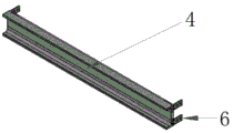
FIG. 2 is a perspective view of the hidden handle body;
FIG. 3 is a front view of the blind handle body;
FIG. 4 is an enlarged view taken at A in FIG. 3;
FIG. 5 is a bottom view of the blind handle body;
FIG. 6 is a top view of the blind handle body;
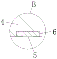
fig. 7 is an enlarged view of fig. 6 at B.
Reference numbers in the figures: 1. a cabinet body group; 2. a drawer set; 3. installing a seam; 4. a hidden handle body; 5. a card slot; 6. a metal connecting member; 7. a screw hole; 8. a clamping block; 9. a slider; 10. a chute.
Detailed Description
The technical solutions in the embodiments of the present invention will be clearly and completely described below with reference to the drawings in the embodiments of the present invention, and it is obvious that the described embodiments are only a part of the embodiments of the present invention, and not all of the embodiments. All other embodiments, which can be derived by a person skilled in the art from the embodiments given herein without making any creative effort, shall fall within the protection scope of the present invention.
Referring to fig. 1 to 7, the present invention provides a technical solution: a C-shaped hidden handle structure convenient to install comprises a cabinet body group 1, wherein a plurality of drawer groups 2 are arranged on the front end face of the cabinet body group 1, an installation seam 3 is arranged between every two adjacent drawer groups 2, a hidden handle body 4 is arranged in the installation seam 3, the cross section of the hidden handle body 4 is C-shaped, a pair of clamping grooves 5 are formed in the side walls of two ends of the hidden handle body 4, a pair of metal connecting pieces 6 are arranged at two ends of the hidden handle body 4, the metal connecting pieces 6 are rectangular and symmetrically arranged about the central axis of the hidden handle body 4, a plurality of screw holes 7 are formed in the surface of each metal connecting piece 6, screws can be inserted into the screw holes 7, thread grooves matched with the screws are formed in the surfaces of the side walls of two sides of the drawer groups 2, the tail ends of the screws can be screwed into the corresponding thread grooves, the metal connecting pieces 6 and the hidden handle body 4 can be fixed at the bottoms of the drawer groups 2 together through the mutual matching between the screws and the screw holes 7, one side of the metal connecting piece 6 close to the hidden handle body 4 is fixedly connected with a clamping block 8, the clamping groove 5 is of a rectangular groove structure, the width of the groove is equal to the width of the clamping block 8, the length of the clamping groove 5 is larger than the thickness of the clamping block 8, the clamping block 8 can pass through the clamping groove 5 and move back and forth along the clamping groove 5, the hidden handle body 4 can be limited by the mutual matching between the clamping groove 5 and the clamping block 8 so as to improve the stability of the hidden handle body 4, thereby preventing the handle from shaking left and right after installation, the side walls of the two sides of the clamping block 8 are fixedly connected with sliding blocks 9, the inner wall surfaces of the two sides of the hidden handle body 4 are respectively provided with a sliding groove 10, the sliding grooves 10 and the sliding blocks 9 are both rectangular, and the width of the sliding groove 10 is equal to the thickness of the sliding block 9, the sliding block 9 can slide back and forth along the sliding groove 10, the stability of the block 8 can be improved by the mutual cooperation between the sliding block 9 and the sliding groove 10, so as to prevent the block from shaking when moving.
The working principle is as follows: when the utility model is used, firstly, the hidden handle body 4 is placed in the mounting seam 3, the top of the hidden handle body is attached to the bottom of the corresponding drawer group 2, then the clamping blocks 8 at the bottoms of the two pairs of metal connecting pieces 6 are respectively aligned with the clamping grooves 5 at the two end side walls of the hidden handle body 4, the clamping blocks 8 are moved inwards along the clamping grooves 5 until the two pairs of metal connecting pieces 6 are respectively attached to the two side walls of the drawer group 2, then, the screw is inserted into the screw hole 7, and the tail end of the screw is respectively screwed into the corresponding thread grooves at the two sides of the drawer group 2, so that the metal connecting pieces 6 and the hidden handle body 4 are fixed at the bottom of the drawer group 2 together through the mutual matching between the screw and the screw hole 7, thereby the hidden handle structure can be arranged in the hidden space of the mounting seam 3, the occupied space is effectively saved, the aesthetic property is improved, and the hidden handle body 4 is C-shaped, when drawer group 2 was taken out to needs, stretch into installation seam 3 and the laminating at the inner wall of dark handle body 4 with the finger, then outside pulling dark handle body 4 can be taken out drawer group 2 from cabinet body group 1, when dark handle body 4 damaged, can pull down dark handle body 4 from the bottom of drawer group 2 through the screw in the screw hole 7 of unscrewing to maintain or change it.
Although embodiments of the present invention have been shown and described, it will be appreciated by those skilled in the art that changes, modifications, substitutions and alterations can be made in these embodiments without departing from the principles and spirit of the utility model, the scope of which is defined in the appended claims and their equivalents.
Claims (7)
1. The utility model provides a hidden handle structure of C type convenient to installation, includes cabinet body group (1), its characterized in that: the front end face of the cabinet body group (1) is provided with a plurality of drawer groups (2), every two adjacent drawer groups (2) are provided with mounting seams (3), and the mounting seams (3) are internally provided with hidden handle bodies (4).
2. A C-shaped hidden handle structure convenient for installation according to claim 1, wherein: the cross section of the hidden handle body (4) is C-shaped, a pair of clamping grooves (5) are formed in the side walls of two ends of the hidden handle body, and a pair of metal connecting pieces (6) are arranged at two ends of the hidden handle body (4).
3. A C-shaped hidden handle structure convenient for installation according to claim 2, wherein: the surface of the metal connecting piece (6) is provided with a plurality of screw holes (7), and one side of the metal connecting piece, which is close to the hidden handle body (4), is fixedly connected with a clamping block (8).
4. A C-shaped hidden handle structure convenient for installation according to claim 2, wherein: the metal connecting piece (6) is rectangular and is symmetrically arranged around the central axis of the hidden handle body (4).
5. A C-shaped hidden handle structure convenient for installation according to claim 2, wherein: the clamping groove (5) is of a rectangular groove structure, the groove width of the clamping groove is equal to the width of the clamping block (8), and the length of the clamping groove (5) is larger than the thickness of the clamping block (8).
6. A C-shaped hidden handle structure convenient for installation according to claim 3, wherein: the side walls of the two sides of the clamping block (8) are fixedly connected with sliding blocks (9), and the inner wall surfaces of the two sides of the hidden handle body (4) are provided with sliding grooves (10).
7. A C-shaped hidden handle structure convenient to install according to claim 6, characterized in that: the sliding groove (10) and the sliding block (9) are both rectangular, and the groove width of the sliding groove (10) is equal to the thickness of the sliding block (9).
Priority Applications (1)
| Application Number | Priority Date | Filing Date | Title |
|---|---|---|---|
| CN202120958356.1U CN215820274U (en) | 2021-05-07 | 2021-05-07 | C-shaped hidden handle structure convenient to install |
Applications Claiming Priority (1)
| Application Number | Priority Date | Filing Date | Title |
|---|---|---|---|
| CN202120958356.1U CN215820274U (en) | 2021-05-07 | 2021-05-07 | C-shaped hidden handle structure convenient to install |
Publications (1)
| Publication Number | Publication Date |
|---|---|
| CN215820274U true CN215820274U (en) | 2022-02-15 |
Family
ID=80188513
Family Applications (1)
| Application Number | Title | Priority Date | Filing Date |
|---|---|---|---|
| CN202120958356.1U Active CN215820274U (en) | 2021-05-07 | 2021-05-07 | C-shaped hidden handle structure convenient to install |
Country Status (1)
| Country | Link |
|---|---|
| CN (1) | CN215820274U (en) |
-
2021
- 2021-05-07 CN CN202120958356.1U patent/CN215820274U/en active Active
Similar Documents
| Publication | Publication Date | Title |
|---|---|---|
| CN103976572A (en) | Multifunctional wardrobe convenient to use | |
| WO2019136793A1 (en) | Wardrobe shelf with wood veneer | |
| CN215820274U (en) | C-shaped hidden handle structure convenient to install | |
| CN104352072A (en) | Splicing type aluminum alloy combined cabinet | |
| CN109645720B (en) | Drawer with double-sided push-pull | |
| CN210961063U (en) | Multipurpose unlimited-expandable grid user-defined furniture | |
| CN202636174U (en) | Drawer lateral board | |
| CN203388516U (en) | Combined ultra-narrow drawer basket | |
| KR200321251Y1 (en) | drawer type casegood furniture | |
| CN214595056U (en) | Metal-enclosed armored drawer | |
| CN205947488U (en) | Drawer basket connection structure | |
| CN213308263U (en) | Good domestic supporter of stability | |
| CN214803305U (en) | Furniture with space-changeable function | |
| CN215776646U (en) | Multifunctional drawer | |
| CN211533393U (en) | Outdoor cabinet with built-in pull goods shelves structure | |
| CN204444907U (en) | Office worker's table side cabinet | |
| CN220522380U (en) | Combined assembled grain bin door | |
| CN211673242U (en) | Corner desk cabinet | |
| CN204994906U (en) | Sectional cabinet | |
| CN216627937U (en) | Drawer with combined structure | |
| CN211048842U (en) | Magnetic mutual exclusion anti-collision functional handle | |
| CN220248557U (en) | Hidden connection structure of cupboard | |
| CN210539839U (en) | Book shelf | |
| CN217471527U (en) | Plastic drawer convenient to assemble and disassemble | |
| CN208491524U (en) | A kind of office cabinet type screen of multifunctional unit |
Legal Events
| Date | Code | Title | Description |
|---|---|---|---|
| GR01 | Patent grant | ||
| GR01 | Patent grant |