CN215790324U - Braided bag production is with tailorring detection device - Google Patents
Braided bag production is with tailorring detection device Download PDFInfo
- Publication number
- CN215790324U CN215790324U CN202121827453.3U CN202121827453U CN215790324U CN 215790324 U CN215790324 U CN 215790324U CN 202121827453 U CN202121827453 U CN 202121827453U CN 215790324 U CN215790324 U CN 215790324U
- Authority
- CN
- China
- Prior art keywords
- fixed
- mechanical frame
- frame
- cutting
- detection device
- Prior art date
- Legal status (The legal status is an assumption and is not a legal conclusion. Google has not performed a legal analysis and makes no representation as to the accuracy of the status listed.)
- Active
Links
Images


Landscapes
- Treatment Of Fiber Materials (AREA)
Abstract
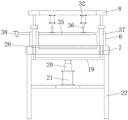
The utility model discloses a cutting detection device for woven bag production, which comprises a mechanical frame A, an inclined rack, a mounting plate A, an infrared sensing device and a mechanical frame B, wherein one side of the mechanical frame B is connected with the bottom of the inclined rack, the upper end of the inclined rack is fixed with the mechanical frame A, two supports are symmetrically mounted at one side, close to the inclined rack, of the upper end of the mechanical frame B, a support rod is fixed in a limiting groove at the middle position of the upper end of each support, the upper end of the support rod is fixed at the bottom of the mounting plate A, two power cylinders B are symmetrically mounted at the bottom of the mounting plate A, close to a cutting position, and the lower ends of the support rods are fixed at two sides of the upper end of a transverse plate. The cutting device has a detection function, can detect whether the cutting length of the woven bag is uniform or not, whether the woven bag is cut askew to generate defective goods or not, finds out defects in time and gives an alarm, and is high in cutting efficiency and neat and flat in cut surface due to the fact that the cutting device performs cutting by adopting a hot cutting function.
Description
Technical Field
The utility model relates to the technical field of cutting detection devices for woven bag production, in particular to a cutting detection device for woven bag production.
Background
Woven bags are also known as snakeskin bags. Is one kind of plastic bag for packing and is produced with polyethylene, polypropylene and other plastic material. The weaving density refers to the number of warp and weft yarns in a 100mm multiplied by 100mm woven fabric.
After a large number of searches, the following results are obtained: chinese utility model patent: the utility model discloses a woven bag cutting device which comprises a base, wherein a first support and a workbench are arranged on the top surface of the base, the workbench is connected with a second support, a servo motor is arranged on the top surface of the base, a first rolling shaft and a winding drum are arranged on the first support, a second rolling shaft and a driving roller are arranged on the second support, a sleeve, a third rolling shaft and a driven roller are arranged on the second support, a supporting rod and a servo driving device are arranged on the base, a cutter rest and a cutter blade are arranged at the bottom of the servo driving device, and a baffle, a spring and a pressing block are arranged on the side wall of the cutter rest. During the use, servo motor drives reel, drive roll, driven voller and rotates, and the braided bag is carried forward, and when knife rest, blade descend to be tailor, the baffle passes through the spring extrusion briquetting and pushes down the braided bag of blade both sides, tailors the back, and the blade rises and the braided bag separation, and the briquetting continues to compress tightly the braided bag, and the braided bag of avoiding being tailor glues on the hot knife up to limiting plate pulling briquetting and braided bag separation, has realized that the braided bag is tailor and has leveled, has improved work efficiency.
The braided bag need the guillootine to cut out in process of production, does not have finished product detection device on the current part cutting device, appears the wastrel easily cutting out the in-process, is difficult to discover, causes the loss to strengthen, and the cost is increased, consequently needs a braided bag production with cutting out detection device.
SUMMERY OF THE UTILITY MODEL
The utility model aims to provide a cutting detection device for woven bag production, which has a detection function, can detect whether the cutting length of a woven bag is uniform, whether defective goods appear due to askew cutting, find defects in time and give an alarm, has the advantages of high cutting efficiency, neat and flat cut surfaces, better use effect, simple structure and convenient and quick operation, and solves the problems that the defective goods easily appear in the cutting process, are not easy to find, cause increased loss and increase cost due to the fact that some cutting devices are not provided with finished product detection devices.
In order to achieve the purpose, the utility model provides the following technical scheme: a cutting detection device for woven bag production comprises a mechanical frame A, an inclined frame, a mounting plate A, an infrared sensing device and a mechanical frame B, one side of the mechanical frame B is connected with the bottom of the inclined frame, the upper end of the inclined frame is fixed with the mechanical frame A, two brackets are symmetrically arranged on one side of the upper end of the mechanical frame B close to the inclined rack, a support rod is fixed in a limit groove at the middle position of the upper end of each bracket, the upper end of the supporting rod is fixed at the bottom of the mounting plate A, two power cylinders B are symmetrically arranged at the bottom of the mounting plate A close to the cutting-off position, the lower ends of the supporting rods are fixed on the two sides of the upper end of the transverse plate, two upright posts are symmetrically fixed on one side of the upper end of the mechanical frame B, which is far away from the inclined frame, the stand is fixed with mounting panel B, two infrared ray induction system are installed to the symmetry on the mounting panel B.
Preferably, two side plates are oppositely installed at the upper end of the mechanical frame A, four guide rollers B are evenly installed on the side plates through bearing seats, three guide rollers A are evenly installed on a cross beam at the lower end of the mechanical frame A through the bearing seats, and the three guide rollers A are distributed among the four guide rollers B at intervals.
Preferably, the lower extreme of power cylinder B's telescopic link B is fixed on the cutter, one side that the cutter is located outside mechanical frame B is equipped with rotatory hand wheel, be equipped with the inner groovy in the mechanical frame B of cutter lower extreme, the inside of inner groovy is fixed with hot grooving, the inside of hot grooving is fixed with the electrothermal tube, the electrothermal tube passes through the electric wire and links together with the control panel, control panel fixes on the landing leg of mechanical frame B lower extreme, two stoppers are installed to the front end of mounting panel A is located power cylinder B's outside symmetry, the bottom of stopper is fixed with the gag lever post, the bottom of gag lever post is fixed with the briquetting.
Preferably, the outer side of the supporting rod is provided with a sleeve, the bottom center position of the transverse plate is fixed on a telescopic rod A of a power cylinder A, and the power cylinder A is fixed on a cross beam at the lower end of the mechanical frame B.
Preferably, the cutter deviates from and is equipped with the conveyer belt on the mechanical frame B of tip rack one side, the conveyer belt is fixed on two cylinders, mechanical frame B is located and installs belt pulley A on the cylinder of front end one side, belt pulley A is together fixed with belt pulley B of lower extreme through the V-belt, belt pulley B is together fixed with the epaxial axle of small motor, small motor passes through the base to be fixed on mechanical frame B's crossbeam, belt pulley B is fixed with the safety cover with belt pulley A's the outside.
Preferably, the lower end of the infrared sensing device is provided with an infrared emitting head.
Compared with the prior art, the utility model has the following beneficial effects: the cutting device has a detection function, can detect whether the cutting length of the woven bag is uniform or not, whether the woven bag is cut askew to generate defective goods or not, find out defects in time and give an alarm, adopts a hot cutting function to cut, and is high in cutting efficiency, neat and flat in cut surface, better in using effect, simple in structure, convenient and fast to operate, capable of reducing cost and improving working efficiency and yield.
Drawings
FIG. 1 is a schematic structural view of the present invention;
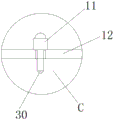
FIG. 2 is a view showing an installation structure of the infrared sensor device according to the present invention;
FIG. 3 is a left side view of the machine frame B of the present invention;
FIG. 4 is a side view of the cutter mounting structure of the present invention;
FIG. 5 is an enlarged view of the structure of FIG. 1 at A according to the present invention;
FIG. 6 is an enlarged view of the utility model at B of FIG. 1;
fig. 7 is an enlarged structural view at C in fig. 2 according to the present invention.
In the figure: 1. a guide roller A; 2. a machine frame A; 3. a side plate; 4. a guide roller B; 5. an inclined frame; 6. a support; 7. a support bar; 8. mounting a plate A; 9. a limiting block; 10. a drum; 11. an infrared sensing device; 12. mounting a plate B; 13. a column; 14. a belt pulley A; 15. a protective cover; 16. a V-belt; 17. a belt pulley B; 18. a control panel; 19. a transverse plate; 20. a telescopic rod A; 21. a power cylinder A; 22. a machine frame B; 23. an electric wire; 24. hot cutting grooves; 25. an electric heating tube; 26. an inner groove; 27. a conveyor belt; 28. a small-sized motor; 29. a base; 30. an infrared emitting head; 31. a limiting groove; 32. a power cylinder B; 33. a limiting rod; 34. briquetting; 35. a cutter; 36. a telescopic rod B; 37. a sleeve; 38. the hand wheel is rotated.
Detailed Description
The technical solutions in the embodiments of the present invention will be clearly and completely described below with reference to the drawings in the embodiments of the present invention, and it is obvious that the described embodiments are only a part of the embodiments of the present invention, and not all of the embodiments. All other embodiments, which can be derived by a person skilled in the art from the embodiments given herein without making any creative effort, shall fall within the protection scope of the present invention.
Referring to fig. 1 to 7, the present invention provides a technical solution of a cutting detection device for woven bag production: the utility model provides a braided bag production is with tailorring detection device, including mechanical frame A2, the inclined frame 5, mounting panel A8, infrared ray induction device 11 and mechanical frame B22, one side of mechanical frame B22 links together with the bottom of inclined frame 5, the upper end of inclined frame 5 is together fixed with mechanical frame A2, mechanical frame A2's upper end is to installing two curb plates 3, evenly install four guide roll B4 through the bearing frame on the curb plate 3, evenly install three guide roll A1 through the bearing frame on the crossbeam of mechanical frame A2 lower extreme, three guide roll A1 interval distribution is between four guide roll B4, the conveying of braided bag is convenient for through setting up mechanical frame A2.
Two supports 6 are installed to mechanical frame B22's upper end one side symmetry near the sloping frame 5, the spacing inslot 31 internal fixation of support 6 upper end intermediate position has bracing piece 7, the bottom at mounting panel A8 is fixed to bracing piece 7's upper end, two power cylinder B32 are installed near cutting off the position symmetry in mounting panel A8's bottom, power cylinder B32's telescopic link B36's lower extreme is fixed on cutter 35, one side that cutter 35 is located mechanical frame B22 is equipped with rotatory hand wheel 38, through setting up power cylinder B32, can make cutter 35 cut the braided bag fast, make the cut-off face level and smooth, can adjust the length of cutter 35 through setting up rotatory hand wheel 38, be suitable for the different braided bag of multiple size and cut.
An inner groove 26 is formed in a mechanical frame B22 at the lower end of the cutter 35, a hot cutting groove 24 is fixed inside the inner groove 26, an electric heating tube 25 is fixed inside the hot cutting groove 24, the electric heating tube 25 is connected with a control panel 18 through an electric wire 23, the control panel 18 is fixed on a support leg at the lower end of the mechanical frame B22, the cutter 35 corresponds to the hot cutting groove 24 at the lower end, the woven bag is convenient to cut, two limiting blocks 9 are symmetrically installed at the outer side, located on a power cylinder B32, of the front end of the mounting plate A8, a limiting rod 33 is fixed at the bottom of each limiting block 9, a pressing block 34 is fixed at the bottom of each limiting rod 33, the pressing block 34 can prevent the woven bag from deviating during hot cutting, and the woven bag is prevented from being askew.
The lower end of the supporting rod 7 is fixed on two sides of the upper end of the transverse plate 19, a sleeve 37 is arranged on the outer side of the supporting rod 7, the bottom center position of the transverse plate 19 is fixed on an expansion rod A20 of a power cylinder A21, the power cylinder A21 is fixed on a cross beam at the lower end of a mechanical frame B22, a conveyor belt 27 is arranged on a mechanical frame B22 on one side of the cutter 35, which is far away from the inclined frame 5, the conveyor belt 27 is fixed on two rollers 10, a belt pulley A14 is arranged on the roller 10 on one side of the front end of the mechanical frame B22, the belt pulley A14 is fixed with a belt pulley B17 at the lower end through a triangular belt 16, a belt pulley B17 is fixed with a shaft on a small motor 28, the small motor 28 is fixed on the cross beam of the mechanical frame B22 through a base 29, and a protective cover 15 is fixed on the outer sides of the belt pulley B17 and the belt pulley A14.
Mechanical frame B22's upper end deviates from one side symmetry of sloping frame 5 and is fixed with two stands 13, be fixed with mounting panel B12 on the stand 13, two infrared ray induction system 11 are installed to the symmetry on mounting panel B12, infrared ray induction system 11's lower extreme is equipped with infrared emission head 30, make through setting up infrared ray induction system 11 and tailor the device and have the detection function, can detect whether unified the shearing length of braided bag, whether cut askew the wastrel that appears, in time discover badly and report to the police, this shearing mechanism adopts the hot cutting function to cut, shearing efficiency is high, the cut surface is neat and level, excellent in use effect, moreover, the steam generator is simple in structure, high operation convenience and high efficiency, and high working efficiency and output are improved.
The motor is designed by using a small low-rotation-speed motor ZGA 37-37 RG, the motor is only used as a reference for the technical field, and the technical field can select motors with the same parameters and functions for installation, debugging and use according to actual production requirements, and the utility model is not described in detail.
The working principle is as follows: set up the parameter on control panel 18, the braided bag that waits to cut conveys the below to cutter 35 through the guide roll on mechanical frame A2, mounting panel A8 on the control bracing piece 7 of power cylinder A21 moves down, drive power cylinder B32 and briquetting 34 on the mounting panel A8 and move down simultaneously, briquetting 34 pushes down the braided bag that waits to cut below, cutter 35 cuts the braided bag under the effect of power cylinder B32, braided bag front end and rear end after the shearing pass through the below of infrared ray induction system 11 in proper order, record the length of braided bag, time data etc. through infrared ray induction system 11, transmit data to control system through the sensor, with this judge whether unified or have the wastrel of braided bag size after the shearing.
Although embodiments of the present invention have been shown and described, it will be appreciated by those skilled in the art that changes, modifications, substitutions and alterations can be made in these embodiments without departing from the principles and spirit of the utility model, the scope of which is defined in the appended claims and their equivalents.
Claims (6)
1. The utility model provides a braided bag production is with tailorring detection device, includes mechanical frame A (2), sloping frame (5), mounting panel A (8), infrared ray induction system (11) and mechanical frame B (22), its characterized in that: one side of mechanical frame B (22) links together with the bottom of sloping frame (5), the upper end and mechanical frame A (2) of sloping frame (5) are fixed together, one side symmetry that the upper end of mechanical frame B (22) is close to sloping frame (5) is installed two supports (6), spacing groove (31) internal fixation of support (6) upper end intermediate position has bracing piece (7), the bottom at mounting panel A (8) is fixed to the upper end of bracing piece (7), the bottom of mounting panel A (8) is close to and cuts off the position symmetry and installs two power cylinder B (32), the lower extreme of bracing piece (7) is fixed in the upper end both sides of diaphragm (19), one side symmetry that the upper end of mechanical frame B (22) deviates from sloping frame (5) is fixed with two stands (13), be fixed with mounting panel B (12) on stand (13), two infrared sensing devices (11) are symmetrically arranged on the mounting plate B (12).
2. The cutting detection device for the woven bag production according to claim 1, wherein: the upper end of mechanical frame A (2) is to installing two curb plates (3), evenly install four guide roll B (4) through the bearing frame on curb plate (3), evenly install three guide roll A (1) through the bearing frame on the crossbeam of mechanical frame A (2) lower extreme, three guide roll A (1) interval distribution is between four guide roll B (4).
3. The cutting detection device for the woven bag production according to claim 1, wherein: the lower end of an expansion link B (36) of the power cylinder B (32) is fixed on the cutting knife (35), a rotary hand wheel (38) is arranged on one side of the cutting knife (35) positioned outside the mechanical frame B (22), an inner groove (26) is arranged in a mechanical frame B (22) at the lower end of the cutting knife (35), a hot cutting groove (24) is fixed inside the inner groove (26), an electric heating tube (25) is fixed inside the hot cutting groove (24), the electric heating pipe (25) is connected with the control panel (18) through an electric wire (23), the control panel (18) is fixed on the support leg at the lower end of the mechanical frame B (22), two limit blocks (9) are symmetrically arranged at the front end of the mounting plate A (8) and positioned at the outer side of the power cylinder B (32), the bottom of the limiting block (9) is fixed with a limiting rod (33), and the bottom of the limiting rod (33) is fixed with a pressing block (34).
4. The cutting detection device for the woven bag production according to claim 1, wherein: the outside of bracing piece (7) is equipped with sleeve (37), the bottom central point of diaphragm (19) puts and fixes on telescopic link A (20) of power cylinder A (21), power cylinder A (21) are fixed on the crossbeam of mechanical frame B (22) lower extreme.
5. The cutting detection device for the woven bag production according to claim 3, wherein: cutter (35) deviate from and are equipped with conveyer belt (27) on the mechanical frame B (22) of tip rack (5) one side, conveyer belt (27) are fixed on two cylinders (10), install belt pulley A (14) on mechanical frame B (22) are located cylinder (10) of front end one side, belt pulley A (14) are together fixed through belt pulley B (17) of V belt (16) and lower extreme, axle on belt pulley B (17) and small motor (28) is fixed together, small motor (28) are fixed on the crossbeam of mechanical frame B (22) through base (29), belt pulley B (17) and the outside of belt pulley A (14) are fixed with safety cover (15).
6. The cutting detection device for the woven bag production according to claim 1, wherein: the lower end of the infrared sensing device (11) is provided with an infrared emitting head (30).
Priority Applications (1)
| Application Number | Priority Date | Filing Date | Title |
|---|---|---|---|
| CN202121827453.3U CN215790324U (en) | 2021-08-06 | 2021-08-06 | Braided bag production is with tailorring detection device |
Applications Claiming Priority (1)
| Application Number | Priority Date | Filing Date | Title |
|---|---|---|---|
| CN202121827453.3U CN215790324U (en) | 2021-08-06 | 2021-08-06 | Braided bag production is with tailorring detection device |
Publications (1)
| Publication Number | Publication Date |
|---|---|
| CN215790324U true CN215790324U (en) | 2022-02-11 |
Family
ID=80128848
Family Applications (1)
| Application Number | Title | Priority Date | Filing Date |
|---|---|---|---|
| CN202121827453.3U Active CN215790324U (en) | 2021-08-06 | 2021-08-06 | Braided bag production is with tailorring detection device |
Country Status (1)
| Country | Link |
|---|---|
| CN (1) | CN215790324U (en) |
-
2021
- 2021-08-06 CN CN202121827453.3U patent/CN215790324U/en active Active
Similar Documents
| Publication | Publication Date | Title |
|---|---|---|
| CN206328622U (en) | A kind of nonwoven production adjustable length portable cutter | |
| CN206528681U (en) | Vegetables and fruits packaging integrated machine | |
| CN103979150B (en) | A kind of cheese wrapping machine | |
| CN215790324U (en) | Braided bag production is with tailorring detection device | |
| CN210619803U (en) | Full-automatic hose cutting blanking machine and hose conveying mechanism thereof | |
| CN210853048U (en) | Ring type winding machine | |
| CN209775699U (en) | cutting device is used in processing of recycled plastic woven sack | |
| CN208828170U (en) | A kind of Full-automatic tire wrapping machine | |
| CN208120300U (en) | Sacked goods intelligence carloader | |
| CN211845091U (en) | Cold compress pastes equipment for packing | |
| CN106400446A (en) | Width-adjustable cutting machine | |
| CN210337097U (en) | Hot-pressing device for bubble film envelope bag making machine | |
| CN208867607U (en) | A kind of rubber adhesive tape storage device | |
| CN203832813U (en) | Cheese packaging machine | |
| CN202829110U (en) | Flanging machine for coil stock edge folding | |
| CN212883607U (en) | Automatic production and sorting device for medicinal packaging materials | |
| CN206395556U (en) | A kind of new type auto correction carton production line | |
| CN206108488U (en) | Work or material rest and use its cutting fabric machine on cloth | |
| CN208561120U (en) | A kind of single layer tentering machine | |
| CN211281753U (en) | Thick sauce material packaging production line is with mechanism that cuts | |
| CN211196742U (en) | Automatic bundling equipment for rod-shaped articles | |
| CN211641125U (en) | Carton cutting device | |
| CN210761527U (en) | High-efficient convenient section of thick bamboo yarn packing apparatus | |
| CN110950131B (en) | Cloth processing apparatus for tailoring | |
| CN213355005U (en) | Bagging device of tire laminating machine |
Legal Events
| Date | Code | Title | Description |
|---|---|---|---|
| GR01 | Patent grant | ||
| GR01 | Patent grant |