CN215789946U - Clamping jaw with rotation function - Google Patents
Clamping jaw with rotation function Download PDFInfo
- Publication number
- CN215789946U CN215789946U CN202122310287.6U CN202122310287U CN215789946U CN 215789946 U CN215789946 U CN 215789946U CN 202122310287 U CN202122310287 U CN 202122310287U CN 215789946 U CN215789946 U CN 215789946U
- Authority
- CN
- China
- Prior art keywords
- clamping jaw
- block
- rotating
- stepping motor
- connecting seat
- Prior art date
- Legal status (The legal status is an assumption and is not a legal conclusion. Google has not performed a legal analysis and makes no representation as to the accuracy of the status listed.)
- Active
Links
Images


Landscapes
- Clamps And Clips (AREA)
Abstract
The utility model discloses a clamping jaw with a rotating function, which comprises a machine shell and a clamping jaw assembly, wherein the machine shell comprises a top cover, a shell and a bottom cover, a stepping motor and a connecting seat are arranged in the shell, the connecting seat is fixed on the stepping motor, a screw rod motor is fixedly arranged on the top cover, a screw rod is arranged on an output shaft of the screw rod motor, a screw rod nut is fixed in the middle of the connecting seat, and the screw rod drives the connecting seat to move up and down through the screw rod nut. The clamping device integrates the rotating function and the clamping function, has small integral volume and compact structure, can realize clamping and simultaneous rotation, and is convenient for transferring workpieces; the rotating seat is directly driven to rotate through the stepping motor, the rotating seat drives the limiting plate to rotate, the transmission effect is good, the rotating precision is high, and the precision of subsequent processing is guaranteed.
Description
Technical Field
The utility model relates to the technical field of manipulators, in particular to a clamping jaw with a rotating function.
Background
The clamping jaw is a tool for clamping articles or releasing articles, the clamp in the production field at present comprises a motor and a clamp, the clamp is connected with the motor, the motor acts to drive the clamp to clamp the articles or release the articles, and the operation is simple.
In the industrial production process, often need use the clamping jaw to snatch and shift the work piece, snatch and shift the in-process and need turn to sometimes to the direction of adjustment work piece, thereby be convenient for subsequent processing, the whole volume of rotatory clamping jaw among the prior art is great, and the structure is complicated, and the cost of manufacture is higher, and rotatory transmission effect is relatively poor simultaneously.
Therefore, it is necessary to invent a clamping jaw with a rotation function to solve the above problems.
SUMMERY OF THE UTILITY MODEL
The utility model aims to provide a clamping jaw with a rotating function, which has the advantages of small volume, good transmission effect and low manufacturing cost.
In order to achieve the purpose, the utility model provides the following technical scheme: a clamping jaw with a rotating function comprises a machine shell and a clamping jaw assembly, wherein the machine shell comprises a top cover, a shell and a bottom cover, a stepping motor and a connecting seat are arranged in the shell, the connecting seat is fixed on the stepping motor, a screw rod motor is fixedly arranged on the top cover, a screw rod is arranged on an output shaft of the screw rod motor, a screw rod nut is fixed in the middle of the connecting seat, and the screw rod drives the connecting seat to move up and down through the screw rod nut;
the clamping jaw assembly comprises a left clamping jaw, a right clamping jaw, a limiting plate, a square stirring block and a rotating seat, the rotating seat comprises an upper layer cylinder and a bottom connecting block, a through groove matched with the square stirring block is formed in the rotating seat, the square stirring block is fixed on an output shaft of the stepping motor, the through groove penetrates through the upper layer cylinder and the bottom connecting block, grooves are symmetrically formed in the lower surface of the bottom connecting block, the grooves on the two sides are communicated with the through groove to form a cross shape, the limiting plate is fixed at the bottom end of the rotating seat, the limiting plate is provided with a sliding channel, the left clamping jaw and the right clamping jaw are arranged in the sliding channel in a sliding way, the top end of the left clamping jaw is hinged with a left poking arm, the top end of the right clamping jaw is hinged with a right poking arm, the left poking arm and the right poking arm are respectively hinged in grooves on two sides through cylindrical pins, and one end of each of the left poking arm and the right poking arm is hinged with the bottom end of the square poking block;
the middle part of the bottom shell is provided with a through hole, a bearing is arranged in the through hole, and the upper-layer cylinder of the rotating seat is arranged in an inner ring of the bearing.
Preferably, the tail end of the output long shaft of the stepping motor is provided with an induction block, and the side wall of the shell is provided with a photoelectric switch corresponding to the position of the induction block.
Preferably, the left clamping jaw and the right clamping jaw are opposite to each other.
Preferably, the inside anti-rotation block that still is provided with of casing, the anti-rotation block adaptation is installed on step motor surface.
Preferably, the top cover is provided with a yielding groove of the screw nut.
Preferably, the bottom end of the top cover is fixedly provided with two stand columns, a guide groove is formed between the two stand columns, the side wall of the connecting seat is transversely fixedly provided with a guide rod, and the guide rod is matched with the guide groove.
The utility model has the technical effects and advantages that: the clamping jaw with the rotating function integrates the rotating function and the clamping function into a whole, has small integral volume and compact structure, can rotate while clamping, and is convenient for transferring workpieces; the rotating seat is directly driven to rotate through the stepping motor, the rotating seat drives the limiting plate to rotate, the transmission effect is good, the rotating precision is high, and the precision of subsequent processing is guaranteed.
Drawings
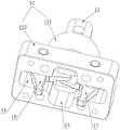
Fig. 1 is a schematic view of the overall structure of the present invention.
Fig. 2 is a schematic view of the overall structure of the present invention in a state of hiding the housing.
FIG. 3 is an enlarged view of portion A of FIG. 2 according to the present invention.
Fig. 4 is a schematic view of the overall structure of the rotary base of the present invention.
FIG. 5 is a schematic view of the entire structure of the bottom cover of the present invention.
Fig. 6 is a schematic view of the overall structure of the limiting plate of the utility model.
In the figure: the device comprises a top cover 1, a shell 2, a bottom cover 3, a stepping motor 4, a connecting seat 5, a screw motor 6, a screw nut 7, a left clamping jaw 8, a right clamping jaw 9, a limiting plate 10, a square shifting block 11, a rotating seat 12, a cylinder 121 on the upper layer, a connecting block 120 at the bottom, a through groove 13, a groove 14, a sliding channel 15, a left shifting arm 16, a right shifting arm 17, a through hole 18, a bearing 19 and an anti-rotation block 20.
Detailed Description
The technical solutions in the embodiments of the present invention will be clearly and completely described below with reference to the drawings in the embodiments of the present invention, and it is obvious that the described embodiments are only a part of the embodiments of the present invention, and not all of the embodiments. All other embodiments, which can be derived by a person skilled in the art from the embodiments given herein without making any creative effort, shall fall within the protection scope of the present invention.
The utility model provides a clamping jaw with a rotating function as shown in figures 1-6, which comprises a machine shell and a clamping jaw assembly, wherein the machine shell comprises a top cover 1, a shell 2 and a bottom cover 3, a stepping motor 4 and a connecting seat 5 are arranged in the shell 2, the connecting seat 5 is fixed on the stepping motor 4, a lead screw motor 6 is fixedly arranged on the top cover 1, a lead screw is arranged on an output shaft of the lead screw motor 6, a lead screw nut 7 is fixed in the middle of the connecting seat 5, and the lead screw drives the connecting seat 5 to move up and down through the lead screw nut 7;
the clamping jaw assembly comprises a left clamping jaw 8, a right clamping jaw 9, a limiting plate 10, a square stirring block 11 and a rotating seat 12, wherein the rotating seat 12 comprises an upper layer cylinder 121 and a bottom connecting block 120, a through groove 13 matched with the square stirring block 11 is formed in the rotating seat 12, the square stirring block 11 is fixed on an output shaft of a stepping motor 4, the through groove 13 penetrates through the upper layer cylinder 121 and the bottom connecting block 120, grooves 14 are symmetrically formed in the lower surface of the bottom connecting block 120, the grooves 14 on the two sides are communicated with the through groove 13 to form a cross shape, the limiting plate 10 is fixed at the bottom end of the rotating seat 12, a sliding channel 15 is formed in the limiting plate 10, the left clamping jaw 8 and the right clamping jaw 9 are arranged in the sliding channel 15 in a sliding mode, a left stirring arm 16 is hinged to the top end of the left clamping jaw 8, a right stirring arm 17 is hinged to the top end of the right clamping jaw 9, the left stirring arm 16 and the right stirring arm 17 are respectively hinged to the grooves 14 on the two sides through cylindrical pins, one end of each of the left shifting arm 16 and the right shifting arm 17 is hinged with the bottom end of the square shifting block 11;
a through hole 18 is formed in the middle of the bottom shell, a bearing 19 is installed inside the through hole 18, and an upper-layer cylinder 121 of the rotating base 12 is installed in an inner ring of the bearing 19.
Furthermore, in the above technical scheme, an induction block is installed at the tail end of the output long shaft of the stepping motor 4, and a photoelectric switch is installed on the side wall of the shell 2 corresponding to the position of the induction block, so that the rotation angle of the clamping jaw can be conveniently set;
further, in the above technical solution, the left clamping jaw 8 and the right clamping jaw 9 are opposite and vertical;
further, in the above technical solution, an anti-rotation block 20 is disposed inside the housing 2 in a matching manner, and the anti-rotation block 20 is mounted on the surface of the stepping motor 4 in an adapting manner;
further, in the above technical scheme, the top cover 1 is provided with a yielding groove of the screw nut 7;
further, in the above technical scheme, two columns are fixed to the bottom end of the top cover 1, a guide groove is formed between the two columns, a guide rod is transversely fixed to the side wall of the connecting seat 5, and the guide rod is matched with the guide groove to provide a guide effect for the connecting seat 5.
This practical theory of operation:
when the clamping device is used, the lead screw motor 6 works to drive the lead screw nut to move upwards through the lead screw so as to drive the connecting seat 5 to move upwards, the connecting seat 5 drives the stepping motor 4 to move upwards and finally drives the square shifting block 11 to move upwards, the square shifting block 11 respectively applies upward pulling force to the left shifting arm 16 and the right shifting arm 17 on two sides, the bottom ends of the shifting arms on two sides simultaneously rotate inwards, so that two clamping jaws are combined to clamp a workpiece, and on the contrary, when the lead screw motor 6 drives the square shifting block 11 to move downwards, the bottom ends of the two shifting arms simultaneously move outwards so as to separate the two clamping jaws;
when the clamping jaw needs to be rotated, only the stepping motor 4 needs to work, the rotating seat 12 can be driven to rotate by the square poking block 11 when the stepping motor 4 rotates, and the limiting plate 10 is driven to rotate by the rotating seat 12, so that the clamping jaw can be directly rotated.
Finally, it should be noted that: although the present invention has been described in detail with reference to the foregoing embodiments, it will be apparent to those skilled in the art that modifications may be made to the embodiments or portions thereof without departing from the spirit and scope of the utility model.
Claims (6)
1. The utility model provides a clamping jaw with rotation function, includes casing and clamping jaw subassembly, its characterized in that: the shell comprises a top cover (1), a shell body (2) and a bottom cover (3), wherein a stepping motor (4) and a connecting seat (5) are arranged inside the shell body (2), the connecting seat (5) is fixed on the stepping motor (4), a lead screw motor (6) is fixedly arranged on the top cover (1), a lead screw is arranged on an output shaft of the lead screw motor (6), a lead screw nut (7) is fixed in the middle of the connecting seat (5), and the lead screw drives the connecting seat (5) to move up and down through the lead screw nut (7);
the clamping jaw assembly comprises a left clamping jaw (8), a right clamping jaw (9), a limiting plate (10), a square stirring block (11) and a rotating seat (12), wherein the rotating seat (12) comprises an upper cylinder (121) and a bottom connecting block (120), a through groove (13) matched with the square stirring block (11) is formed in the rotating seat (12), the square stirring block (11) is fixed on an output shaft of a stepping motor (4), the through groove (13) penetrates through the upper cylinder (121) and the bottom connecting block (120), a groove (14) is symmetrically formed in the lower surface of the bottom connecting block (120), grooves (14) on two sides and the through groove (13) are communicated to form a cross shape, the limiting plate (10) is fixed at the bottom end of the rotating seat (12), a sliding channel (15) is formed in the limiting plate (10), and the left clamping jaw (8) and the right clamping jaw (9) are slidably arranged in the sliding channel (15), the top end of the left clamping jaw (8) is hinged with a left poking arm (16), the top end of the right clamping jaw (9) is hinged with a right poking arm (17), the left poking arm (16) and the right poking arm (17) are hinged in grooves (14) on two sides through cylindrical pins respectively, and one end of each of the left poking arm (16) and the right poking arm (17) is hinged with the bottom end of the square poking block (11);
a through hole (18) is formed in the middle of the bottom shell, a bearing (19) is installed inside the through hole (18), and an upper-layer cylinder (121) of the rotating seat (12) is installed in an inner ring of the bearing (19).
2. A jaw with rotating function according to claim 1, characterized in that: an induction block is installed at the tail end of an output long shaft of the stepping motor (4), and a photoelectric switch is installed on the side wall of the shell (2) corresponding to the position of the induction block.
3. A jaw with rotating function according to claim 1, characterized in that: the left clamping jaw (8) and the right clamping jaw (9) are opposite.
4. A jaw with rotating function according to claim 1, characterized in that: the anti-rotation device is characterized in that an anti-rotation block (20) is further arranged inside the shell (2), and the anti-rotation block (20) is installed on the surface of the stepping motor (4) in an adaptive mode.
5. A jaw with rotating function according to claim 1, characterized in that: the top cover (1) is provided with a yielding groove of the screw nut (7).
6. A jaw with rotating function according to claim 1, characterized in that: the bottom end of the top cover (1) is fixedly provided with two stand columns, a guide groove is formed between the two stand columns, the side wall of the connecting seat (5) is transversely fixedly provided with a guide rod, and the guide rod is matched with the guide groove.
Priority Applications (1)
| Application Number | Priority Date | Filing Date | Title |
|---|---|---|---|
| CN202122310287.6U CN215789946U (en) | 2021-09-24 | 2021-09-24 | Clamping jaw with rotation function |
Applications Claiming Priority (1)
| Application Number | Priority Date | Filing Date | Title |
|---|---|---|---|
| CN202122310287.6U CN215789946U (en) | 2021-09-24 | 2021-09-24 | Clamping jaw with rotation function |
Publications (1)
| Publication Number | Publication Date |
|---|---|
| CN215789946U true CN215789946U (en) | 2022-02-11 |
Family
ID=80165818
Family Applications (1)
| Application Number | Title | Priority Date | Filing Date |
|---|---|---|---|
| CN202122310287.6U Active CN215789946U (en) | 2021-09-24 | 2021-09-24 | Clamping jaw with rotation function |
Country Status (1)
| Country | Link |
|---|---|
| CN (1) | CN215789946U (en) |
Cited By (1)
| Publication number | Priority date | Publication date | Assignee | Title |
|---|---|---|---|---|
| CN114759492A (en) * | 2022-03-22 | 2022-07-15 | 南方电网电力科技股份有限公司 | Split type wire stripping instrument |
-
2021
- 2021-09-24 CN CN202122310287.6U patent/CN215789946U/en active Active
Cited By (2)
| Publication number | Priority date | Publication date | Assignee | Title |
|---|---|---|---|---|
| CN114759492A (en) * | 2022-03-22 | 2022-07-15 | 南方电网电力科技股份有限公司 | Split type wire stripping instrument |
| CN114759492B (en) * | 2022-03-22 | 2024-04-02 | 南方电网电力科技股份有限公司 | Split type wire stripping tool |
Similar Documents
| Publication | Publication Date | Title |
|---|---|---|
| CN106945030B (en) | Rotary lifting mechanical arm | |
| CN215789946U (en) | Clamping jaw with rotation function | |
| CN215789945U (en) | Rotary clamping jaw with Z-axis lifting function | |
| CN213439531U (en) | Rotary platform for manufacturing mechanical parts | |
| CN218503391U (en) | Drilling tool for machining bearing seat | |
| CN209681671U (en) | A kind of clamping device of tooling | |
| CN208557277U (en) | A kind of auto parts clamping device | |
| CN217596562U (en) | Machining center machine tool fixture switching device | |
| CN213615337U (en) | Clamping tool suitable for milling hexagonal nut | |
| CN215510921U (en) | Frock clamp of brake master cylinder processing usefulness | |
| CN212042807U (en) | Flange spot facing work positioning fixture in electrical control valve | |
| CN211614369U (en) | Radial drill is used in valve production | |
| CN111054838A (en) | Automatic stamping fixture for die parts | |
| CN2093716U (en) | Multi-purpose rotatory working table | |
| CN216938090U (en) | Automatic feeding device for machining motorcycle stamping parts | |
| CN201389925Y (en) | Lens hole punching machine | |
| CN214979563U (en) | Novel digit control machine tool arm | |
| CN210065101U (en) | Novel cap screwing machine | |
| CN216299088U (en) | Fixing device is used in mould accessory production | |
| CN218744983U (en) | Gear step end face drilling equipment | |
| CN213437380U (en) | Punching and positioning tool for engine suspension support | |
| CN220162415U (en) | Processing fixing device for production of electric valve | |
| CN215469722U (en) | Reaming device for hardware production and processing | |
| CN216126872U (en) | Adjustable machining center special fixture | |
| CN218656886U (en) | Automatic change drilling equipment for part |
Legal Events
| Date | Code | Title | Description |
|---|---|---|---|
| GR01 | Patent grant | ||
| GR01 | Patent grant |