CN215786510U - Crowded mesopore nailing mould structure of china department part that car loudspeaker were used - Google Patents
Crowded mesopore nailing mould structure of china department part that car loudspeaker were used Download PDFInfo
- Publication number
- CN215786510U CN215786510U CN202121784749.1U CN202121784749U CN215786510U CN 215786510 U CN215786510 U CN 215786510U CN 202121784749 U CN202121784749 U CN 202121784749U CN 215786510 U CN215786510 U CN 215786510U
- Authority
- CN
- China
- Prior art keywords
- nailing
- die
- mesopore
- punch
- plate
- Prior art date
- Legal status (The legal status is an assumption and is not a legal conclusion. Google has not performed a legal analysis and makes no representation as to the accuracy of the status listed.)
- Active
Links
Images


Abstract
The utility model relates to the technical field of automobile punching, in particular to a washer part center hole extruding and nailing die structure for an automobile horn, which comprises an upper die and a lower die coupled with the upper die, wherein the upper die is sequentially provided with an upper die base, an upper padding plate, an upper clamping plate and an upper stripping plate from top to bottom; the lower die is equipped with die holder, lower bolster from supreme down in proper order, it punches a hole to be equipped with mesopore and nailing on the lower bolster, the mesopore is corresponding with crowded mesopore drift position, the nailing punches a hole and the nailing drift position is corresponding. The punch is not easy to break during punching and material returning, the service life of the punch is prolonged, the yield of products is improved, the production efficiency is improved, the production cost is reduced and the like.
Description
Technical Field
The utility model relates to the technical field of automobile stamping, in particular to a washer part center hole extruding and nailing die structure for an automobile horn.
Background
The stamping is a forming method in which a press and a die are used to apply external force to a plate, a strip, a pipe, a profile, etc. to cause plastic deformation or separation, thereby obtaining a workpiece (stamped part) of a desired shape and size. The stamping die is essential technological equipment for stamping production, and the quality, production efficiency, production cost and the like of stamping parts are directly related to the design and manufacture of the die.
Because four rivets are small, a punching needle is easy to break when a traditional die is used for punching and returning materials, and a product is easy to have few nails or short nails, so that the reject ratio of the product is very high, the production efficiency is reduced, and the production cost of an enterprise is increased.
SUMMERY OF THE UTILITY MODEL
In order to solve the technical problems, the utility model adopts the following technical scheme:
the utility model provides an crowded mesopore nailing mould structure of china department part that car loudspeaker were used, includes mould and the bed die with last mould looks coupling, its characterized in that: the upper die is sequentially provided with an upper die base, an upper base plate, an upper clamping plate and an upper stripping plate from top to bottom, the upper base plate is provided with a spring and is connected with the upper stripping plate, the upper die is also provided with a middle extruding hole punch and a nailing punch, and one end of the middle extruding hole punch sequentially penetrates through the upper stripping plate and the upper clamping plate from bottom to top and is fixed on the upper base plate;
the lower die is equipped with die holder, lower bolster in proper order from supreme down, it punches a hole to be equipped with mesopore and nailing on the lower bolster, the mesopore is corresponding with crowded mesopore drift position, the nailing punches a hole and is corresponding with nailing drift position, the lower bolster still is equipped with location nail and lower push rod.
The upper die base is provided with a die handle and a knock-off rod, one end of the knock-off rod is connected with the die handle, and the other end of the knock-off rod sequentially penetrates out of the upper backing plate, the upper clamping plate and the upper stripper plate from top to bottom.
Specifically, the nailing drift quantity of going up the mould is no less than 4, the nailing drift is around crowded mesopore drift center and is annular array distribution.
Specifically, the nailing punches are arrayed annularly around the center of the central hole in a position corresponding to the position of the nailing punch.
Preferably, the upper die is provided with a punch screw, and the punch screw fixes the central extrusion hole punch on the upper base plate.
And a lower ejector rod is arranged in the nailing punching hole and connected with the lower ejector rod.
The lower template and the lower backing plate are fixed on the lower die base through screws in a penetrating mode.
The utility model has the following beneficial effects:
the utility model enables the nailing punch and the middle extruding hole punch to be stressed uniformly during material returning through the upper stripping plate, the spring and the striking rod structure, ensures that the punch is not easy to break during stamping and material returning, prolongs the service life, simultaneously, the lower ejector rod in the nailing punch is matched with the nailing punch to punch out rivets with good quality on a stamping part, effectively avoids the phenomenon of few nails or short nails of a product, improves the product quality and the production efficiency, and reduces the production cost.
Drawings
FIG. 1 is a schematic view of the structure of the present invention.
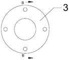
Fig. 2 is a schematic structural diagram of a stamping part.
Fig. 3 is a schematic view at a-a in fig. 1.
Fig. 4 is a schematic structural view at B-B in fig. 2.
In the figure: 1-an upper die holder; 2-a lower die holder; 3-stamping parts; 11-upper backing plate; 12-upper splint; 13-removing the plate; 14-extruding a central hole punch; 15-nailing a punch; 16-a die shank; 17-beating a rod; 18-punch screws; 19-a spring; 21-lower backing plate; 22-a lower template; 23-mesopores; 24-punching by nailing; 25-positioning nails; 26-lower push rod; 27-lower mandril.
Detailed Description
In the description of the present invention, it should be noted that, unless otherwise explicitly specified or limited, the terms "mounted," "connected," and "connected" are to be construed broadly, e.g., as meaning either a fixed connection, a removable connection, or an integral connection; can be mechanically or electrically connected; they may be connected directly or indirectly through intervening media, or they may be interconnected between two elements. The specific meaning of the above terms in the present invention can be understood by those of ordinary skill in the art through specific situations.
The technical solutions in the embodiments of the present invention will be clearly and completely described below with reference to the drawings in the embodiments of the present invention, and it is obvious that the described embodiments are only a part of the embodiments of the present invention, and not all of the embodiments. All other embodiments, which can be derived by a person skilled in the art from the embodiments given herein without making any creative effort, shall fall within the protection scope of the present invention.
As shown in fig. 1-4, a washer part center hole extruding and nailing die structure for automobile horn comprises an upper die and a lower die coupled with the upper die, and is characterized in that: the upper die is sequentially provided with an upper die holder 1, an upper backing plate 11, an upper clamping plate 12 and an upper stripping plate 13 from top to bottom, the upper backing plate 11 is provided with a spring 19 and is connected with the upper stripping plate 13, the upper die is also provided with a middle extruding hole punching head 14 and a nailing punching head 15, and one end of the middle extruding hole punching head 14 sequentially penetrates through the upper stripping plate 13 and the upper clamping plate 12 from bottom to top and is fixed on the upper backing plate 11;
the bed die is equipped with lower bolster 2, lower bolster 21, lower bolster 22 from supreme down in proper order, be equipped with mesopore 23 and nailing 24 that punches a hole on the lower bolster 22, mesopore 23 is corresponding with crowded mesopore drift 14 positions, the nailing 24 that punches a hole is corresponding with nailing drift 15 positions, the lower bolster still is equipped with location nail 25 and lower push rod 26. The positioning nails 25 can quickly place the product on the lower die to an accurate position, so that the yield and the production efficiency of the product are improved.
As shown in fig. 3, the upper die holder is further provided with a die handle 16 and a striking rod 17, one end of the striking rod 17 is connected with the die handle 16, and the other end of the striking rod 17 sequentially penetrates through the upper backing plate 11, the upper clamping plate 12 and the upper stripper plate 13 from top to bottom. When the nailing punch 15 is returned, the upper stripping plate 13 can enable the stamping part 3 to be stressed uniformly and smoothly, so that the nailing punch 15 and the middle extruding hole punch 14 are not easy to break off during stamping and returning, and meanwhile, the spring 19 is connected with the upper stripping plate 13, so that the nailing punch 15 and the middle extruding hole punch 14 can be further helped to return materials conveniently and safely.
The number of the nailing punch heads 15 of the upper die is not less than 4, and the nailing punch heads 15 are distributed in an annular array around the center of the middle extruding hole punch head 14.
The nailing punches 24 are arranged in an annular array around the centre of the central hole 23 at a position corresponding to the position of the nailing punch 15.
The upper die is provided with a punch screw 18, and the punch screw 18 fixes the central extrusion punch 14 to the upper backing plate 11. The upper cushion plate 11 and the upper clamping plate 12 are fixed through screws, and the upper stripper plate 13 and the upper clamping plate 12 are also fixed through screw connection.
A lower ejector rod 27 is arranged in the nailing punched hole 24, and the lower ejector rod 27 is connected with the lower ejector rod 26. When the nailing punch 15 punches, the lower ejector rod 27 pushes the stamping part 3 in the nailing punch hole 24, so that a good rivet is punched on the stamping part 13 in a matching manner, and the phenomenon of few nails or short nails is avoided.
The lower backing plate 21 and the lower template 22 are fixed on the lower die base 2 through screws.
The working principle is as follows:
the upper die and the lower die are mounted on a punching machine, materials are placed on the lower die and accurately placed through positioning nails 25, a punch slide block moves downwards to enable the upper die to move downwards and be coupled with the lower die, the middle extruding hole punching head 24 and the nailing punching head 15 move downwards to punch rivets and polish the middle holes on the stamping part 3, then the punching machine drives the middle extruding hole punching head 24 and the nailing punching head 15 to ascend, the upper stripping plate 13 enables the nailing punching head 15 to stably withdraw from the stamping part 3, the die shank 16 drives a striking rod 17 to enable the stamping part 3 to be stressed uniformly, and the middle extruding hole punching head 24 is withdrawn from the stamping part 3.
The utility model enables the nailing punch and the middle extruding hole punch to be stressed uniformly during punching and material returning through the upper stripping plate, the spring and the striking rod structure, ensures that the punch is not easy to break during punching and material returning, prolongs the service life, simultaneously, the lower ejector rod in the nailing punch is matched with the nailing punch to punch out rivets with good quality on a punching piece, effectively avoids the phenomenon of few nails or short nails of a product, improves the product quality and the production efficiency, and reduces the production cost.
In the description of the present invention, it is to be understood that the terms "center", "longitudinal", "lateral", "up", "down", "front", "back", "left", "right", "vertical", "horizontal", "top", "bottom", "inner", "outer", and the like, indicate orientations or positional relationships based on those shown in the drawings, and are used only for convenience in describing the present invention and for simplicity in description, and do not indicate or imply that the referenced devices or elements must have a particular orientation, be constructed and operated in a particular orientation, and thus, are not to be construed as limiting the present invention.
Although embodiments of the present invention have been shown and described, it will be appreciated by those skilled in the art that changes, modifications, substitutions and alterations can be made in these embodiments without departing from the principles and spirit of the utility model, the scope of which is defined in the appended claims and their equivalents.
Claims (7)
1. The utility model provides an crowded mesopore nailing mould structure of china department part that car loudspeaker were used, includes mould and the bed die with last mould looks coupling, its characterized in that: the upper die is sequentially provided with an upper die base (1), an upper backing plate (11), an upper clamping plate (12) and an upper stripping plate (13) from top to bottom, the upper backing plate (11) is provided with a spring (19) and connected with the upper stripping plate (13), the upper die is further provided with a middle extruding hole punching head (14) and a nailing punching head (15), and one end of the middle extruding hole punching head (14) sequentially penetrates through the upper stripping plate (13) and the upper clamping plate (12) from bottom to top and is fixed on the upper backing plate (11);
the lower mould is equipped with lower bolster (2), lower bolster (21), lower bolster (22) from supreme down in proper order, be equipped with mesopore (23) and nailing punch a hole (24) on lower bolster (22), mesopore (23) is corresponding with crowded mesopore drift (24) position, the nailing punches a hole (24) and nailing drift (15) position is corresponding, the lower bolster still is equipped with location nail (25) and lower push rod (26).
2. The washer part center hole punching nailing die structure for the automobile horn according to claim 1, wherein: the upper die base is further provided with a die handle (16) and a striking rod (17), one end of the striking rod (17) is connected with the die handle (16), and the other end of the striking rod sequentially penetrates through the upper padding plate (11), the upper clamping plate (12) and the upper stripper plate (13) from top to bottom.
3. The washer part center hole punching nailing die structure for the automobile horn according to claim 1, wherein: the punching head (15) number of the upper die is not less than 4, and the punching head (15) is distributed in an annular array around the center of the middle extruding hole punching head (14).
4. The washer part center hole punching nailing die structure for the automobile horn as claimed in claims 1 and 3, wherein: the nailing punched holes (24) are annularly arrayed around the center of the middle hole (23) and correspond to the nailing punch head (15).
5. The washer part center hole punching nailing die structure for the automobile horn according to claim 1, wherein: the upper die is provided with a punch head screw (18), and the punch head screw (18) fixes the central extruding punch head (14) on the upper backing plate (11).
6. The washer part center hole punching nailing die structure for the automobile horn according to claim 1, wherein: a lower ejector rod (27) is arranged in the nailing punching hole (24), and the lower ejector rod (27) is connected with a lower push rod (26).
7. The washer part center hole punching nailing die structure for the automobile horn according to claim 1, wherein: the lower backing plate (21) and the lower template (22) are fixed on the lower die base (2) through screws in a penetrating mode.
Priority Applications (1)
| Application Number | Priority Date | Filing Date | Title |
|---|---|---|---|
| CN202121784749.1U CN215786510U (en) | 2021-08-02 | 2021-08-02 | Crowded mesopore nailing mould structure of china department part that car loudspeaker were used |
Applications Claiming Priority (1)
| Application Number | Priority Date | Filing Date | Title |
|---|---|---|---|
| CN202121784749.1U CN215786510U (en) | 2021-08-02 | 2021-08-02 | Crowded mesopore nailing mould structure of china department part that car loudspeaker were used |
Publications (1)
| Publication Number | Publication Date |
|---|---|
| CN215786510U true CN215786510U (en) | 2022-02-11 |
Family
ID=80127602
Family Applications (1)
| Application Number | Title | Priority Date | Filing Date |
|---|---|---|---|
| CN202121784749.1U Active CN215786510U (en) | 2021-08-02 | 2021-08-02 | Crowded mesopore nailing mould structure of china department part that car loudspeaker were used |
Country Status (1)
| Country | Link |
|---|---|
| CN (1) | CN215786510U (en) |
-
2021
- 2021-08-02 CN CN202121784749.1U patent/CN215786510U/en active Active
Similar Documents
| Publication | Publication Date | Title |
|---|---|---|
| CN201960043U (en) | Novel cantilever type bidirectional punching die | |
| CN201969774U (en) | Cantilever type bidirectional punching die | |
| CN109013870A (en) | A kind of application method of composite die | |
| CN215786510U (en) | Crowded mesopore nailing mould structure of china department part that car loudspeaker were used | |
| CN217798429U (en) | Blanking, drawing and punching composite die and equipment using same | |
| CN216757937U (en) | Integrative stamping forming equipment of metal staple bolt batched | |
| CN216324593U (en) | Multi-process bending integrated forming die mechanism | |
| CN210412176U (en) | Spoke forming and punching integrated die | |
| CN212093972U (en) | Aluminum plate overlap forming composite die | |
| CN213997352U (en) | Hydrogen fuel cell bipolar plate mould pressing integrative device that punches a hole | |
| CN209969352U (en) | Deep-drawing and edge-extruding composite die | |
| CN212384369U (en) | Punching forming die for button battery pole piece | |
| CN210877138U (en) | Stamping die slider mechanism convenient to take off material | |
| CN210847937U (en) | Hole flanging and flanging composite die for end cover | |
| CN110538922A (en) | progressive die for multiple thinning drawing and reverse drawing | |
| CN220880202U (en) | Progressive die for stamping product | |
| CN216540475U (en) | Novel continuous cutting and bending structure capable of realizing negative angle bending | |
| CN220049685U (en) | Vehicle license plate stamping forming die | |
| CN216175880U (en) | Lamp holder blanking connection punching die | |
| CN218963808U (en) | High-precision, convenient and efficient safe pole stamping die structure | |
| CN218486984U (en) | Stamping die for products in disc | |
| CN215199213U (en) | A blanking compound die that punches a hole for car lighting fixture | |
| CN216828197U (en) | Stamping die | |
| CN211990491U (en) | Antiskid plate punching forming die | |
| CN220760784U (en) | Reinforcement secondary forming structure and stamping die |
Legal Events
| Date | Code | Title | Description |
|---|---|---|---|
| GR01 | Patent grant | ||
| GR01 | Patent grant |