CN215759828U - Curtain wall assembling, mounting and positioning device - Google Patents
Curtain wall assembling, mounting and positioning device Download PDFInfo
- Publication number
- CN215759828U CN215759828U CN202120498377.XU CN202120498377U CN215759828U CN 215759828 U CN215759828 U CN 215759828U CN 202120498377 U CN202120498377 U CN 202120498377U CN 215759828 U CN215759828 U CN 215759828U
- Authority
- CN
- China
- Prior art keywords
- groove
- mounting
- sliding
- gear
- racks
- Prior art date
- Legal status (The legal status is an assumption and is not a legal conclusion. Google has not performed a legal analysis and makes no representation as to the accuracy of the status listed.)
- Active
Links
Images




Landscapes
- Curtains And Furnishings For Windows Or Doors (AREA)
Abstract
The utility model discloses a curtain wall assembling, mounting and positioning device, which relates to the field of curtain wall construction equipment and adopts the technical scheme that the device comprises a rectangular base, wherein a horizontal mounting groove is formed in the middle of the base, a horizontal adjusting mechanism is arranged in the mounting groove in a sliding manner, the horizontal adjusting mechanism comprises two mounting blocks which are connected with the mounting groove in a sliding manner, a through straight groove is formed in each mounting block, the straight groove is vertical to the projection of the mounting groove in the vertical direction, and a vertical adjusting mechanism is arranged in each straight groove; the fixed lug that sets up in upper end of apron sets up the spout on the lug, and the spout is parallel with the projection of mounting groove in the horizontal direction, sliding connection positioning mechanism in the spout. The utility model has the beneficial effects that: simple structure, convenient to use saves the manual work, improves positioning accuracy and location efficiency, simplifies the location step, improves the efficiency of curtain installation.
Description
Technical Field
The utility model relates to the field of auxiliary equipment for curtain wall construction, in particular to a positioning device for assembling, installing and positioning a curtain wall.
Background
Along with the development of various cities in China, the number of super high-rise buildings is increased, the unit curtain wall is the main stream outer enclosure form of the super high-rise buildings, and along with the increasing requirements of people on the appearance of the buildings, the geometric shape of the curtain wall surface is also more complicated. The unit curtain wall panels of the same project may have a variety of specifications, which makes assembly of the unit curtain wall panels, especially installation and positioning of the components, very difficult.
The installation location of each component all adopts the installer manual work to measure the location at present stage, and positioning accuracy is low, and positioning error is big, because the curtain system of building outward appearance may have multiple different specifications, the manual work is measured the location and is leaded to producing positioning deviation easily, and positioning efficiency is low moreover.
SUMMERY OF THE UTILITY MODEL
Aiming at the technical problem, the utility model provides a curtain wall assembling, mounting and positioning device.
The technical scheme includes that the device comprises a rectangular base, a horizontal mounting groove is formed in the middle of the base, a horizontal adjusting mechanism is arranged in the mounting groove in a sliding mode and comprises a first gear rotatably arranged in the middle of the mounting groove, two sides of the first gear are respectively provided with a first rack, teeth of the two first racks are opposite, the two first racks are respectively meshed with the first gear, each first rack is connected with the mounting groove in a sliding mode, one end, opposite to the two first racks, of each first rack is fixedly provided with a mounting block, each mounting block is connected with the mounting groove in a sliding mode, a through straight groove is formed in each mounting block, the straight groove is perpendicular to the projection of the mounting groove in the vertical direction, and a vertical adjusting mechanism is arranged in each straight groove;
a cover plate is fixedly arranged on the bottom plate, a through hole is formed in the middle of the cover plate in a penetrating mode, the through hole is coaxial with the first gear, an adjusting knob is fixedly arranged on one side of the first gear, penetrates through the through hole and extends to the outer side of the cover plate;
the upper end of apron is fixed to be set up the lug, set up the spout on the lug, the spout with the mounting groove is parallel at the projection of horizontal direction, sliding connection positioning mechanism in the spout.
Preferably, the vertical adjusting mechanism comprises a second gear rotationally connected with the straight groove, second racks are respectively arranged on two sides of the second gear, the two second racks are respectively meshed with the second gear, the two second racks are parallel to each other, the two second racks are respectively in sliding connection with the straight groove, adjusting blocks are respectively fixedly arranged at the opposite ends of the two second racks, each adjusting block is in sliding connection with the mounting groove, and an adjusting rod is fixedly arranged at one end of each adjusting block of the second rack according to the principle of the adjusting blocks;
and an adjusting knob is fixedly arranged on one side of the second gear, and the adjusting knob extends to the outer side of the mounting block.
Preferably, the positioning mechanism comprises a rectangular strip-shaped cross rod, the cross rod is connected with the sliding chute in a sliding manner, a vertical rod is fixedly arranged at one end of the cross rod, the vertical rod is perpendicular to the cross rod, a sliding block is connected onto the vertical rod in a sliding manner, a scale rod is connected onto the sliding block in a sliding manner, and the scale rod is perpendicular to the vertical rod and the cross rod respectively;
and one end of the scale rod is fixedly provided with a positioning pointer.
Preferably, the sliding block is rectangular and blocky, one side of the sliding block is provided with a sliding groove, the sliding block is connected with the vertical rod in a sliding mode through the sliding groove, one side, away from the sliding groove, of the sliding block is provided with a through groove, and the through groove is perpendicular to the sliding groove;
threaded holes are respectively formed in one sides of the through groove and the sliding groove, each threaded hole is communicated with the through groove and the sliding groove, and each threaded hole is in threaded connection with one locking bolt.
The technical scheme provided by the embodiment of the utility model has the following beneficial effects: simple structure, convenient to use saves the manual work, improves positioning accuracy and location efficiency, simplifies the location step, improves the efficiency of curtain installation.
Drawings
FIG. 1 is a diagram illustrating the effect of the present invention.
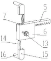
Fig. 2 is a schematic view of a horizontal adjustment mechanism according to an embodiment of the present invention.
Fig. 3 is a schematic overall structure diagram of the second embodiment of the present invention.
Fig. 4 is a schematic view of a positioning mechanism according to an embodiment of the present invention.
FIG. 5 is a schematic structural diagram of a slider according to an embodiment of the present invention.
Wherein the reference numerals are: 1. a base; 2. mounting grooves; 3. a horizontal adjustment mechanism; 4. a first gear; 5. a first rack; 6. mounting blocks; 7. a straight groove; 8. a vertical adjustment mechanism; 9. a cover plate; 10. a bump; 11. a chute; 12. a positioning mechanism; 13. a second gear; 14. a second rack; 15. an adjusting block; 16. adjusting a rod; 17. a cross bar; 18. a vertical rod; 19. a slider; 20. a graduated rod; 21. positioning a pointer; 22. a sliding groove; 23. a through groove; 24. locking the bolt; 25. a column; 26. curtain wall panels.
Detailed Description
In order to make the objects, technical solutions and advantages of the present invention more apparent, the present invention is described in further detail below with reference to the accompanying drawings and embodiments. Of course, the specific embodiments described herein are merely illustrative of the utility model and are not intended to be limiting.
It should be noted that the embodiments and features of the embodiments of the present invention may be combined with each other without conflict.
In the description of the present invention, it is to be understood that the terms "central," "longitudinal," "lateral," "upper," "lower," "front," "rear," "left," "right," "vertical," "horizontal," "top," "bottom," "inner," "outer," and the like are used in the orientation or positional relationship indicated in the drawings, which are merely for convenience in describing the utility model and to simplify the description, and are not intended to indicate or imply that the referenced device or element must have a particular orientation, be constructed and operated in a particular orientation, and are therefore not to be construed as limiting the utility model. Furthermore, the terms "first", "second", etc. are used for descriptive purposes only and are not to be construed as indicating or implying relative importance or implicitly indicating the number of technical features indicated. Thus, a feature defined as "first," "second," etc. may explicitly or implicitly include one or more of that feature. In the description of the utility model, the meaning of "a plurality" is two or more unless otherwise specified.
In the description of the utility model, it is to be noted that, unless otherwise explicitly specified or limited, the terms "mounted", "connected" and "connected" are to be construed broadly, e.g. as being fixed or detachable or integrally connected; can be mechanically or electrically connected; they may be connected directly or indirectly through intervening media, or they may be interconnected between two elements. The specific meaning of the above terms in the creation of the present invention can be understood by those of ordinary skill in the art through specific situations.
Example 1
Referring to fig. 1 to 5, the utility model provides a curtain wall assembling, mounting and positioning device, which comprises a rectangular base 1, wherein a horizontal mounting groove 2 is formed in the middle of the base 1, a horizontal adjusting mechanism 3 is arranged in the mounting groove 2 in a sliding manner, the horizontal adjusting mechanism 3 comprises a first gear 4 rotatably arranged in the middle of the mounting groove 2, two sides of the first gear 4 are respectively provided with a first rack 5, teeth of the two first racks 5 are opposite, the two first racks 5 are respectively meshed with the first gear 4, each first rack 5 is in sliding connection with the mounting groove 2, one end of each first rack 5, which is opposite to the other end, is respectively and fixedly provided with a mounting block 6, each mounting block 6 is in sliding connection with the mounting groove 2, a through straight groove 7 is formed in the mounting block 6, the straight groove 7 is perpendicular to the projection of the mounting groove 2 in the vertical direction, and a vertical adjusting mechanism 8 is arranged in each straight groove 7;
a cover plate 9 is fixedly arranged on the bottom plate, a through hole which penetrates through the middle part of the cover plate 9 is arranged, the through hole is coaxial with the first gear 4, an adjusting knob is fixedly arranged on one side of the first gear 4, and the adjusting knob penetrates through the through hole and extends to the outer side of the cover plate 9; through rotating the adjust knob, drive first gear 4 and rotate to drive two first racks 5 and move to opposite direction, realize the regulation of two installation piece 6 positions.
The fixed lug 10 that sets up in upper end of apron 9 sets up spout 11 on the lug 10, and spout 11 is parallel with the projection of mounting groove 2 in the horizontal direction, sliding connection positioning mechanism 12 in the spout 11.
The vertical adjusting mechanism 8 comprises a second gear 13 rotatably connected with the straight groove 7, two sides of the second gear 13 are respectively provided with a second rack 14, the two second racks 14 are respectively meshed with the second gear 13, the two second racks 14 are parallel, the two second racks 14 are respectively connected with the straight groove 7 in a sliding manner, one ends of the two second racks 14, which are opposite to each other, are respectively fixedly provided with an adjusting block 15, each adjusting block 15 is connected with the mounting groove 2 in a sliding manner, and one end of each adjusting block 15, which is based on the principle of the second rack 14, is fixedly provided with an adjusting rod 16;
an adjusting knob is fixedly arranged on one side of the second gear 13 and extends to the outer side of the mounting block 6;
by rotating the adjusting knob, the second gear 13 is driven to rotate, so that the two second racks 14 are driven to move in opposite directions, and the positions of the two adjusting blocks 15 are adjusted.
The positioning mechanism 12 comprises a rectangular strip-shaped cross rod 17, the cross rod 17 is connected with the sliding chute 11 in a sliding manner, one end of the cross rod 17 is fixedly provided with a vertical rod 18, the vertical rod 18 is perpendicular to the cross rod 17, the vertical rod 18 is connected with a sliding block 19 in a sliding manner, the sliding block 19 is connected with a scale rod 20 in a sliding manner, and the scale rod 20 is perpendicular to the vertical rod 18 and the cross rod 17 respectively;
one end of the graduated rod 20 is fixedly provided with a positioning pointer 21;
the rod bodies of the cross rod 17, the vertical rod 18 and the scale rod 20 are all provided with scale marks.
The sliding block 19 is rectangular and in a block shape, a sliding groove 22 is formed in one side of the sliding block 19, the sliding block 19 is connected with the vertical rod 18 in a sliding mode through the sliding groove 22, a through groove 23 penetrating through the sliding block 19 is formed in one side, away from the sliding groove 22, of the sliding block 19, and the through groove 23 is perpendicular to the sliding groove 22;
threaded holes are respectively formed in one sides of the through groove 23 and the sliding groove 22, each threaded hole is communicated with the through groove 23 and the sliding groove 22, and each threaded hole is in threaded connection with one locking bolt 24.
When the device is used, the vertical adjusting mechanism 8 and the horizontal adjusting mechanism 3 are adjusted to enable the 4 adjusting rods 16 on the two sides of the base 1 to be inserted into the technical holes in the upright post 25, the vertical adjusting mechanism 8 and the horizontal adjusting mechanism 3 are respectively provided with the fastening bolts, and the fastening bolts are used for fastening the first gear 4 and the second gear 13, so that the situation that the position of the adjusting rod 16 is changed in the using process of the device, and the device is not firmly connected with the technical holes is avoided.
Adjust positioning mechanism 8, loosen locking bolt 24 on lug 10, remove horizontal pole 17, make scale rod 20 be located the outside of curtain wall panel 26, height through adjusting slide 19, confirm the height of scale rod 20, remove scale rod 20, make scale rod 20 stretch out suitable length according to the drawing, and locking bolt 24 on the locking slide 19, use location pointer 21 to make the location mark on curtain wall panel 26, when fixing a position next place curtain wall panel, only need to adjust pole 16 and insert different fabrication holes, positioning mechanism 12's position can not produce the change, location pointer 21 can make the location on curtain wall panel 26, location convenient and fast, save the manual work.
The above description is only for the purpose of illustrating the preferred embodiments of the present invention and is not to be construed as limiting the utility model, and any modifications, equivalents, improvements and the like that fall within the spirit and principle of the present invention are intended to be included therein.
Claims (4)
1. The curtain wall assembling, mounting and positioning device is characterized by comprising a rectangular base (1), wherein a horizontal mounting groove (2) is formed in the middle of the base (1), a horizontal adjusting mechanism (3) is arranged in the mounting groove (2) in a sliding manner, the horizontal adjusting mechanism (3) comprises a first gear (4) rotatably arranged in the middle of the mounting groove (2), two first racks (5) are respectively arranged on two sides of the first gear (4), teeth of the two first racks (5) are opposite, the two first racks (5) are respectively meshed with the first gear (4), each first rack (5) is in sliding connection with the mounting groove (2), a mounting block (6) is respectively fixedly arranged at one end, opposite to each other, of the two first racks (5), and each mounting block (6) is in sliding connection with the mounting groove (2), a through straight groove (7) is formed in the mounting block (6), the straight groove (7) is perpendicular to the projection of the mounting groove (2) in the vertical direction, and a vertical adjusting mechanism (8) is arranged in each straight groove (7);
a cover plate (9) is fixedly arranged on the bottom plate, a through hole which penetrates through the bottom plate is formed in the middle of the cover plate (9), the through hole is coaxial with the first gear (4), an adjusting knob is fixedly arranged on one side of the first gear (4), and the adjusting knob penetrates through the through hole and extends to the outer side of the cover plate (9);
the upper end of apron (9) is fixed and is set up lug (10), set up spout (11) on lug (10), spout (11) with mounting groove (2) are parallel at the projection of horizontal direction, sliding connection positioning mechanism (12) in spout (11).
2. The curtain wall assembling, mounting and positioning device according to claim 1, wherein the vertical adjusting mechanism (8) comprises a second gear (13) rotatably connected with the straight groove (7), two second racks (14) are respectively arranged on two sides of the second gear (13), the two second racks (14) are respectively meshed with the second gear (13), the two second racks (14) are parallel, the two second racks (14) are respectively connected with the straight groove (7) in a sliding manner, adjusting blocks (15) are respectively fixedly arranged at the opposite ends of the two second racks (14), each adjusting block (15) is connected with the mounting groove (2) in a sliding manner, and an adjusting rod (16) is fixedly arranged at one end of each adjusting block (15) which is connected with the corresponding second rack (14);
and an adjusting knob is fixedly arranged on one side of the second gear (13) and extends to the outer side of the mounting block (6).
3. The curtain wall assembling, mounting and positioning device according to claim 1, wherein the positioning mechanism (12) comprises a cross bar (17) in a rectangular strip shape, the cross bar (17) is slidably connected with the sliding chute (11), a vertical bar (18) is fixedly arranged at one end of the cross bar (17), the vertical bar (18) is perpendicular to the cross bar (17), a sliding block (19) is slidably connected on the vertical bar (18), a scale rod (20) is slidably connected on the sliding block (19), and the scale rod (20) is perpendicular to the vertical bar (18) and the cross bar (17) respectively;
one end of the scale rod (20) is fixedly provided with a positioning pointer (21).
4. The curtain wall assembling, mounting and positioning device according to claim 3, wherein the sliding block (19) is rectangular and in a block shape, a sliding groove (22) is formed in one side of the sliding block (19), the sliding block (19) is slidably connected with the vertical rod (18) through the sliding groove (22), a through groove (23) penetrates through one side, facing away from the sliding groove (22), of the sliding block (19), and the through groove (23) is perpendicular to the sliding groove (22);
threaded holes are formed in one sides of the through groove (23) and the sliding groove (22) respectively, each threaded hole is communicated with the through groove (23) and the sliding groove (22), and each threaded hole is in threaded connection with one locking bolt (24).
Priority Applications (1)
| Application Number | Priority Date | Filing Date | Title |
|---|---|---|---|
| CN202120498377.XU CN215759828U (en) | 2021-03-09 | 2021-03-09 | Curtain wall assembling, mounting and positioning device |
Applications Claiming Priority (1)
| Application Number | Priority Date | Filing Date | Title |
|---|---|---|---|
| CN202120498377.XU CN215759828U (en) | 2021-03-09 | 2021-03-09 | Curtain wall assembling, mounting and positioning device |
Publications (1)
| Publication Number | Publication Date |
|---|---|
| CN215759828U true CN215759828U (en) | 2022-02-08 |
Family
ID=80093862
Family Applications (1)
| Application Number | Title | Priority Date | Filing Date |
|---|---|---|---|
| CN202120498377.XU Active CN215759828U (en) | 2021-03-09 | 2021-03-09 | Curtain wall assembling, mounting and positioning device |
Country Status (1)
| Country | Link |
|---|---|
| CN (1) | CN215759828U (en) |
Cited By (2)
| Publication number | Priority date | Publication date | Assignee | Title |
|---|---|---|---|---|
| CN115182463A (en) * | 2022-08-17 | 2022-10-14 | 中建八局第一建设有限公司 | Reinforced connection structure of external structure of building and main part |
| CN118422805A (en) * | 2024-07-03 | 2024-08-02 | 山西工程科技职业大学 | Assembled building curtain wall and installation method thereof |
-
2021
- 2021-03-09 CN CN202120498377.XU patent/CN215759828U/en active Active
Cited By (3)
| Publication number | Priority date | Publication date | Assignee | Title |
|---|---|---|---|---|
| CN115182463A (en) * | 2022-08-17 | 2022-10-14 | 中建八局第一建设有限公司 | Reinforced connection structure of external structure of building and main part |
| CN115182463B (en) * | 2022-08-17 | 2023-08-11 | 中建八局第一建设有限公司 | Reinforcing connection structure of building externally-hung structure and main body |
| CN118422805A (en) * | 2024-07-03 | 2024-08-02 | 山西工程科技职业大学 | Assembled building curtain wall and installation method thereof |
Similar Documents
| Publication | Publication Date | Title |
|---|---|---|
| CN215759828U (en) | Curtain wall assembling, mounting and positioning device | |
| CN209945235U (en) | Measuring device for welding seam angle of building steel structure | |
| CN201964885U (en) | Telescopic level | |
| CN211081069U (en) | Wall post positioner of modularization assembled building | |
| CN112161548A (en) | Super high-rise building engineering measuring equipment | |
| CN212444997U (en) | Quick positioning and mounting device for door and window accessories | |
| CN202846258U (en) | Precise displacement platform | |
| CN215445646U (en) | Fixing device for three-dimensional electronic altimeter | |
| CN212363190U (en) | A adjust support that is used for building engineering quality to detect with spirit level | |
| CN209066818U (en) | Auxiliary guiding ruler component for the production of metope ash cake | |
| CN220247628U (en) | Assembled building templates strutting arrangement | |
| CN216516991U (en) | Straightness orthotic devices hangs down based on steel construction building | |
| CN219572995U (en) | Adjustable template linear displacement detection equipment | |
| CN118653722A (en) | Supporting device convenient for construction of glued plate ceiling | |
| CN216266755U (en) | Positioning device for leaked steel bars of wall window board | |
| CN220954086U (en) | Quick mounting structure of curtain for building decoration | |
| CN215410962U (en) | Special measuring device of building engineering design | |
| CN215254989U (en) | Intelligent parking space connection structure with high butt joint strength | |
| CN220565509U (en) | Hanging type aluminum veneer curtain wall | |
| CN216830593U (en) | Manufacturing and mounting mould for stair fence and handrail | |
| CN220912248U (en) | Frame type coil checking device | |
| CN211181561U (en) | Engineering cost progress management device | |
| CN216348495U (en) | Shaft body diameter automatic checkout device | |
| CN214473187U (en) | Adjustable oxygen detector binding mechanism | |
| CN220036193U (en) | Steel column locating rack |
Legal Events
| Date | Code | Title | Description |
|---|---|---|---|
| GR01 | Patent grant | ||
| GR01 | Patent grant |