CN215748024U - High-automation-degree rapid-feeding numerical control machining center - Google Patents
High-automation-degree rapid-feeding numerical control machining center Download PDFInfo
- Publication number
- CN215748024U CN215748024U CN202121979267.1U CN202121979267U CN215748024U CN 215748024 U CN215748024 U CN 215748024U CN 202121979267 U CN202121979267 U CN 202121979267U CN 215748024 U CN215748024 U CN 215748024U
- Authority
- CN
- China
- Prior art keywords
- numerical control
- machining center
- control machining
- installation base
- mounting
- Prior art date
- Legal status (The legal status is an assumption and is not a legal conclusion. Google has not performed a legal analysis and makes no representation as to the accuracy of the status listed.)
- Active
Links
Images


Abstract
The utility model discloses a numerical control machining center with high automation degree and capability of feeding quickly, which comprises an installation base, wherein an arch frame is fixedly installed at the top of the installation base, a numerical control machining center body is fixedly installed inside the arch frame, two installation plates are arranged at the top of the installation base, two extrusion plates are arranged at the top of the installation plates, and two motors are fixedly installed on the right side of the installation base. The mounting plate is arranged for mounting the extrusion plates, the extrusion plates are arranged for fixing a workpiece to be processed, the workpiece is moved to the bottom of the numerical control machining center body for processing through the left and right movement of the extrusion plates, and meanwhile, the two extrusion plates are driven to move through the motor so as to realize rapid feeding.
Description
Technical Field
The utility model relates to the technical field of numerical control machining centers, in particular to a numerical control machining center which is high in automation degree and capable of feeding quickly.
Background
Machining centers have evolved from numerically controlled milling machines. The numerical control milling machine is mainly different from a numerical control milling machine in that a machining center has the capability of automatically exchanging machining tools, the machining tools on a main shaft can be changed through an automatic tool changing device in one-time clamping by installing tools with different purposes on a tool magazine, and multiple machining functions are realized, and the numerical control machining center is a high-efficiency automatic machine tool which is composed of mechanical equipment and a numerical control system and is suitable for machining complex parts. The numerical control machining center is one of numerical control machines with highest yield and most extensive application in the world at present. The comprehensive processing capacity is strong, a workpiece can finish more processing contents after being clamped once, the processing precision is high, batch workpieces with medium processing difficulty are processed, the efficiency is 5-10 times that of common equipment, especially, the batch processing method can finish processing which cannot be finished by a plurality of common equipment, and the batch processing method is more suitable for single-piece processing or medium-small batch multi-variety production with complex shapes and high precision requirements.
When the numerical control machining center is used, due to the fact that the feeding device is arranged at the bottom of the numerical control machining center, the workpiece needs to be taken out of the material after machining is finished, efficiency is low, and using requirements cannot be met.
SUMMERY OF THE UTILITY MODEL
The utility model aims to provide a numerical control machining center which is high in automation degree and capable of feeding rapidly, has the advantage of being capable of feeding and discharging rapidly, and solves the problem that when the numerical control machining center is used, due to the fact that feeding equipment is arranged at the bottom of the numerical control machining center, materials need to be taken out after machining of a workpiece is finished, and efficiency is low.
In order to achieve the purpose, the utility model provides the following technical scheme: the utility model provides a but high quick numerical control machining center of feeding of degree of automation, includes the installation base, the top fixed mounting of installation base has the bow member, the inside fixed mounting of bow member has numerical control machining center body, the top of installation base is provided with two mounting panels, the top of mounting panel is provided with two stripper plates, the right side fixed mounting of installation base has two motors, the bottom fixed mounting of mounting panel has four installation poles, the inside intercommunication of installation base has the outlet pipe, the bottom intercommunication of mounting panel has the drain pipe.
Preferably, two first chutes are formed in the mounting base, two adjusting rods are slidably connected inside the first chutes, and the tops of the adjusting rods are fixedly connected with the bottom of the mounting plate.
Preferably, the output shaft of the motor is fixedly provided with a first threaded rod, and the first threaded rod penetrates through the inside of the mounting base and is rotatably connected with the adjusting rod through a first thread.
Preferably, the top of installation base and the one side that is located the relative keeping away from of first spout have all seted up the guide way, the installation pole runs through to the inside of installation base through the guide way, the bottom of installation pole and the inside rotation that is located the guide way are connected with the gyro wheel, the bottom of gyro wheel and the bottom contact of guide way inner chamber.
Preferably, two second chutes are formed in the mounting plate, two second sliding blocks are connected to the inside of the second chutes in a sliding manner, and the tops of the second sliding blocks are fixedly connected with the bottom of the extrusion plate.
Preferably, the front of mounting panel is rotated through the bearing and is connected with the second threaded rod, the second threaded rod runs through to the inside of mounting panel and rotates with the second slider through the second screw and be connected, the inside of mounting panel and the bottom intercommunication that is located the second spout have the aqueduct, one side and the drain pipe intercommunication that the aqueduct is close to relatively.
Compared with the prior art, the utility model has the following beneficial effects:
1. the installation base is arranged for installing the arch-shaped frame, the arch-shaped frame is arranged for installing the numerical control machining center body, the installation plate is arranged for installing the extrusion plates, the extrusion plates are arranged for fixing a workpiece to be machined, the workpiece is moved to the bottom of the numerical control machining center body to be machined through the left and right movement of the extrusion plates, the two extrusion plates are driven by the motor to move simultaneously so as to achieve quick feeding, and the problems that when the numerical control machining center is used, due to the fact that feeding equipment is arranged at the bottom, the workpiece needs to be taken out after machining is finished, and efficiency is low are solved.
2. The utility model realizes the adjustment of the mounting plate through the cooperation between the first sliding chute and the adjusting rod, thereby enabling the mounting plate at the bottom of the body of the numerical control machining center to move rightwards, the mounting plate at the left side of the body of the numerical control machining center moves to the bottom of the body of the numerical control machining center to realize quick machining and simultaneously facilitate feeding, the mounting plate is driven to move through the cooperation between the motor, the first threaded rod and the adjusting rod, thereby sending a workpiece to the bottom of the body of the numerical control machining center to machine and moving the workpiece which is machined at the top of the mounting plate at the bottom of the body of the numerical control machining center to move rightwards and take off, thereby realizing quick blanking, the mounting plate is convenient to move through the arrangement of the guide groove for accommodating the mounting rod, the mounting plate is convenient to move through the cooperation between the mounting rod, the guide groove and the roller, and the extrusion plate is installed through the cooperation between the second sliding block and the second sliding chute, the extrusion plate is adjusted through the cooperation between the second threaded rod and the second sliding block, so that the workpiece is clamped.
Drawings
FIG. 1 is a schematic structural view of the present invention;
FIG. 2 is a schematic cross-sectional view of the present invention;
FIG. 3 is a schematic cross-sectional view of the mounting plate of the present invention;
FIG. 4 is a schematic side sectional view of the present invention.
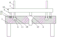
In the figure: 1. installing a base; 2. an arch frame; 3. mounting a rod; 4. a drain pipe; 5. adjusting a rod; 6. a pressing plate; 7. mounting a plate; 8. a numerical control machining center body; 9. a motor; 10. a first chute; 11. a first threaded rod; 12. a water outlet pipe; 13. a water conduit; 14. a second slider; 15. a second threaded rod; 16. a second chute; 17. a guide groove; 18. and a roller.
Detailed Description
The technical solutions in the embodiments of the present invention will be clearly and completely described below with reference to the drawings in the embodiments of the present invention, and it is obvious that the described embodiments are only a part of the embodiments of the present invention, and not all of the embodiments. All other embodiments, which can be derived by a person skilled in the art from the embodiments given herein without making any creative effort, shall fall within the protection scope of the present invention.
In the description herein, it is to be understood that the terms "center," "upper," "lower," "front," "rear," "left," "right," "vertical," "horizontal," "top," "bottom," "inner," "outer," and the like are used in the orientations and positional relationships indicated in the drawings to facilitate the description of the patent and to simplify the description, but do not indicate or imply that the referenced device or element must have a particular orientation, be constructed and operated in a particular orientation, and thus are not to be considered limiting of the patent. In the description of the present application, it should be noted that unless otherwise explicitly stated or limited, the terms "mounted," "connected," and "disposed" are to be construed broadly and can, for example, be fixedly connected, disposed, detachably connected, disposed, or integrally connected and disposed. The specific meaning of the above terms in this patent may be understood by those of ordinary skill in the art as appropriate.
Referring to fig. 1-4, a high-automation-degree fast-feeding numerical control machining center comprises an installation base 1, an arch frame 2 is fixedly installed at the top of the installation base 1, a numerical control machining center body 8 is fixedly installed inside the arch frame 2, two installation plates 7 are arranged at the top of the installation base 1, two extrusion plates 6 are arranged at the top of the installation plates 7, two motors 9 are fixedly installed at the right side of the installation base 1, four installation rods 3 are fixedly installed at the bottom of the installation plates 7, a water outlet pipe 12 is communicated with the inside of the installation base 1, a water outlet pipe 4 is communicated with the bottom of the installation plates 7, the arch frame 2 is installed by arranging the installation base 1, the numerical control machining center body 8 is installed by arranging the arch frame 2, the extrusion plates 6 are installed by arranging the installation plate 7, the extrusion plates 6 are used for fixing a workpiece to be machined, the workpiece is moved to the bottom of a numerical control machining center body 8 to be machined through the left and right movement of an extrusion plate 6, meanwhile, two extrusion plates 6 are driven to move through a motor 9 so as to achieve rapid feeding, two first sliding grooves 10 are formed in an installation base 1, two adjusting rods 5 are connected to the inside of the first sliding grooves 10 in a sliding mode, the tops of the adjusting rods 5 are fixedly connected with the bottom of an installation plate 7, the installation plate 7 is adjusted through the cooperation between the first sliding grooves 10 and the adjusting rods 5, therefore, the installation plate 7 located at the bottom of the numerical control machining center body 8 moves rightwards, the installation plate 7 located at the left side of the numerical control machining center body 8 moves to the bottom of the numerical control machining center body 8 so as to achieve rapid machining and facilitate feeding, a first threaded rod 11 is fixedly installed on an output shaft of the motor 9, the first threaded rod 11 penetrates through the inside of the installation base 1 and is rotatably connected with the adjusting rods 5 through first threads, the mounting plate 7 is driven to move through the cooperation between the motor 9 and the first threaded rod 11 and the adjusting rod 5, so that a workpiece is conveyed to the bottom of the body 8 of the numerical control machining center to be machined, and the machined workpiece at the top of the mounting plate 7 at the bottom of the body 8 of the numerical control machining center is moved rightwards to be taken down, so that rapid blanking is realized, guide grooves 17 are formed in the top of the mounting base 1 and the side, which is relatively far away from the first sliding groove 10, of the mounting rod 3 penetrates into the mounting base 1 through the guide grooves 17, rollers 18 are rotatably connected to the bottom of the mounting rod 3 and the inside of the guide grooves 17, the bottom of the rollers 18 is contacted with the bottom of the inner cavity of the guide grooves 17, the mounting rod 3 is accommodated through the guide grooves 17, the mounting rod 3 is arranged, the mounting plate 7 is convenient to move through the cooperation between the guide grooves 17 and the rollers 18, two second sliding grooves 16 are formed in the mounting plate 7, inside sliding connection of second spout 16 has two second sliders 14, the top of second slider 14 and the bottom fixed connection of stripper plate 6, cooperation through between second slider 14 and the second spout 16 realizes installing stripper plate 6, the front of mounting panel 7 is connected with second threaded rod 15 through bearing rotation, second threaded rod 15 runs through to the inside of mounting panel 7 and rotates with second slider 14 through the second screw and be connected, the inside of mounting panel 7 and the bottom intercommunication that is located second spout 16 have aqueduct 13, one side and the drain pipe 4 intercommunication that aqueduct 13 is close to relatively, realize adjusting stripper plate 6 through the cooperation between second threaded rod 15 and the second slider 14, thereby realize carrying out the centre gripping to the work piece.
When the device is used, the mounting plate 7 is adjusted through the cooperation between the first sliding groove 10 and the adjusting rod 5, so that the mounting plate 7 at the bottom of the body 8 of the numerical control machining center moves rightwards, the mounting plate 7 at the left side of the body 8 of the numerical control machining center moves to the bottom of the body 8 of the numerical control machining center to realize rapid machining and simultaneously facilitate feeding, the mounting plate 7 is driven to move through the cooperation between the motor 9, the first threaded rod 11 and the adjusting rod 5, so that a workpiece is sent to the bottom of the body 8 of the numerical control machining center to be machined, the workpiece with the machined top of the mounting plate 7 at the bottom of the body 8 of the numerical control machining center moves rightwards and is taken down, so that rapid blanking is realized, the mounting rod 3 is accommodated through the arrangement of the guide groove 17, the mounting plate 7 is convenient to move through the cooperation between the mounting rod 3, the guide groove 17 and the roller 18, and the mounting plate 6 is realized through the cooperation between the second sliding block 14 and the second sliding groove 16, the extrusion plate 6 is adjusted through the cooperation between the second threaded rod 15 and the second sliding block 14, so that the workpiece is clamped.
Although embodiments of the present invention have been shown and described, it will be appreciated by those skilled in the art that changes, modifications, substitutions and alterations can be made in these embodiments without departing from the principles and spirit of the utility model, the scope of which is defined in the appended claims and their equivalents.
Claims (6)
1. The utility model provides a but numerical control machining center of high quick feeding of degree of automation, includes installation base (1), its characterized in that: the utility model discloses a numerical control machining center, including installation base (1), the top fixed mounting of installation base (1) has bow member (2), the inside fixed mounting of bow member (2) has numerical control machining center body (8), the top of installation base (1) is provided with two mounting panels (7), the top of mounting panel (7) is provided with two stripper plates (6), the right side fixed mounting of installation base (1) has two motors (9), the bottom fixed mounting of mounting panel (7) has four installation poles (3), the inside intercommunication of installation base (1) has outlet pipe (12), the bottom intercommunication of mounting panel (7) has drain pipe (4).
2. The numerical control machining center with high automation degree and rapid feeding function according to claim 1, characterized in that: two first chutes (10) are formed in the mounting base (1), two adjusting rods (5) are connected to the inside of the first chutes (10) in a sliding mode, and the tops of the adjusting rods (5) are fixedly connected with the bottom of the mounting plate (7).
3. The numerical control machining center with high automation degree and rapid feeding function according to claim 1, characterized in that: the output shaft fixed mounting of motor (9) has first threaded rod (11), first threaded rod (11) run through to the inside of installation base (1) and through first screw and regulation pole (5) rotation connection.
4. The numerical control machining center with high automation degree and rapid feeding function according to claim 1, characterized in that: guide way (17) have all been seted up at the top of installation base (1) and be located the relative one side of keeping away from of first spout (10), installation pole (3) run through to the inside of installation base (1) through guide way (17), the inside rotation that the bottom of installation pole (3) just is located guide way (17) is connected with gyro wheel (18), the bottom of gyro wheel (18) and the bottom contact of guide way (17) inner chamber.
5. The numerical control machining center with high automation degree and rapid feeding function according to claim 1, characterized in that: two second chutes (16) are formed in the mounting plate (7), two second sliding blocks (14) are connected to the inside of the second chutes (16) in a sliding mode, and the tops of the second sliding blocks (14) are fixedly connected with the bottom of the extrusion plate (6).
6. The numerical control machining center with high automation degree and rapid feeding function according to claim 1, characterized in that: the front of mounting panel (7) is rotated through the bearing and is connected with second threaded rod (15), second threaded rod (15) run through the inside of mounting panel (7) and rotate with second slider (14) through the second screw and be connected, the inside of mounting panel (7) and the bottom intercommunication that is located second spout (16) have aqueduct (13), one side and drain pipe (4) intercommunication that aqueduct (13) are close to relatively.
Priority Applications (1)
| Application Number | Priority Date | Filing Date | Title |
|---|---|---|---|
| CN202121979267.1U CN215748024U (en) | 2021-08-23 | 2021-08-23 | High-automation-degree rapid-feeding numerical control machining center |
Applications Claiming Priority (1)
| Application Number | Priority Date | Filing Date | Title |
|---|---|---|---|
| CN202121979267.1U CN215748024U (en) | 2021-08-23 | 2021-08-23 | High-automation-degree rapid-feeding numerical control machining center |
Publications (1)
| Publication Number | Publication Date |
|---|---|
| CN215748024U true CN215748024U (en) | 2022-02-08 |
Family
ID=80077404
Family Applications (1)
| Application Number | Title | Priority Date | Filing Date |
|---|---|---|---|
| CN202121979267.1U Active CN215748024U (en) | 2021-08-23 | 2021-08-23 | High-automation-degree rapid-feeding numerical control machining center |
Country Status (1)
| Country | Link |
|---|---|
| CN (1) | CN215748024U (en) |
-
2021
- 2021-08-23 CN CN202121979267.1U patent/CN215748024U/en active Active
Similar Documents
| Publication | Publication Date | Title |
|---|---|---|
| CN204912965U (en) | Horizontal lathe of screw thread hole is milled simultaneously at large -scale cylinder work piece both ends | |
| CN211516763U (en) | Fixing device for numerical control machining | |
| CN212918388U (en) | Turning and milling composite numerical control machine tool | |
| CN211163084U (en) | Two-way power multiaxis clamping processingequipment | |
| CN215748024U (en) | High-automation-degree rapid-feeding numerical control machining center | |
| CN111266613B (en) | Lathe capable of automatically replacing turning tool | |
| CN209998927U (en) | Full-automatic internal polishing machine | |
| CN202606873U (en) | High-efficiency two-spindle numerically-controlled lathe | |
| CN216126870U (en) | High-efficient machining center tilting mechanism | |
| CN202763606U (en) | Semi-automatic chamfering machine | |
| CN215658959U (en) | CNC numerical control machining center is originally pressed pressure head base for lathe | |
| CN211053205U (en) | Automatic clamping numerically controlled lathe | |
| CN210099555U (en) | Lathe automatic control system based on PLC | |
| CN212121670U (en) | Automatic feeding machine for numerical control lathe | |
| CN209774068U (en) | Auxiliary positioning device for assembling of numerical control machining center | |
| CN210938063U (en) | Automatic hole turning and chamfering mechanism | |
| CN210731777U (en) | Numerical control cutter convenient to switch | |
| CN214444749U (en) | Stable fixed equipment of centre gripping for digit control machine tool | |
| CN219582308U (en) | Full-automatic numerical control planer-type milling machine convenient for cleaning scraps for precision machining | |
| CN212682449U (en) | Numerical control tool rest for machining numerical control machine tool | |
| CN213054487U (en) | Machining device for mechanical die | |
| CN220838935U (en) | Clamp for numerical control machine tool | |
| CN220533645U (en) | Feeding mechanism for numerical control machining center | |
| CN217859969U (en) | Convenient numerical control of adjusting anchor clamps for processing | |
| CN217702522U (en) | Micro-distance high-precision feeding device for machine tool |
Legal Events
| Date | Code | Title | Description |
|---|---|---|---|
| GR01 | Patent grant | ||
| GR01 | Patent grant |