CN215733760U - Direct-current high-temperature-resistant motor - Google Patents
Direct-current high-temperature-resistant motor Download PDFInfo
- Publication number
- CN215733760U CN215733760U CN202121270960.1U CN202121270960U CN215733760U CN 215733760 U CN215733760 U CN 215733760U CN 202121270960 U CN202121270960 U CN 202121270960U CN 215733760 U CN215733760 U CN 215733760U
- Authority
- CN
- China
- Prior art keywords
- hole
- motor body
- temperature
- sides
- direct
- Prior art date
- Legal status (The legal status is an assumption and is not a legal conclusion. Google has not performed a legal analysis and makes no representation as to the accuracy of the status listed.)
- Active
Links
Images


Landscapes
- Motor Or Generator Frames (AREA)
- Motor Or Generator Cooling System (AREA)
Abstract
The utility model belongs to the field of motors, and particularly relates to a direct-current high-temperature-resistant motor which comprises a motor body, wherein a connecting wire is arranged at the top of the motor body, a protection mechanism is arranged on the motor body and comprises an upper shell and a lower shell, the upper shell is matched with the lower shell, upper connecting seats are respectively arranged on two sides of the bottom of the upper shell, lower connecting seats are respectively arranged on two sides of the top of the lower shell, a rotating hole with an opening at one side is formed in the top of the upper connecting seat, a connecting rod is rotatably arranged in the rotating hole, a placing hole with an opening at one side is formed in the top of the lower connecting seat, the connecting rod is matched with the placing hole, a pin slot is formed in the bottom of the lower connecting seat, a moving hole is formed in one side of the connecting rod, and a moving plate is slidably arranged in the moving hole. The motor body heat dissipation structure is reasonable in design, the protection mechanism is convenient to mount, and the heat dissipation efficiency of the motor body can be improved through the heat dissipation fins, so that the high-temperature resistance of the motor body is improved.
Description
Technical Field
The utility model relates to the technical field of motors, in particular to a direct-current high-temperature-resistant motor.
Background
The dc motor is a rotating electrical machine that can convert dc electrical energy into mechanical energy or vice versa. The motor can realize the mutual conversion of direct current electric energy and mechanical energy. When it is operated as a motor, it is a dc motor, converting electrical energy into mechanical energy.
At present, when an existing direct current motor is used, the motor generates heat easily, and the heat is not easy to dissipate, so that the high-temperature resistance performance is poor, the use of the motor is affected, a protection mechanism is not convenient to install on the motor, and the high-temperature resistance performance of the motor is not convenient to improve.
SUMMERY OF THE UTILITY MODEL
The utility model aims to solve the defects that a protection mechanism is inconvenient to install on a motor and the high-temperature resistance of the motor is inconvenient to improve in the prior art, and provides a direct-current high-temperature-resistant motor.
In order to achieve the purpose, the utility model adopts the following technical scheme:
a direct-current high-temperature-resistant motor comprises a motor body, wherein a connecting wire is arranged at the top of the motor body, a protection mechanism is arranged on the motor body and comprises an upper shell and a lower shell, the upper shell is matched with the lower shell, the two sides of the bottom of the upper shell are both provided with upper connecting seats, the two sides of the top of the lower shell are both provided with lower connecting seats, the top of the upper connecting seats is provided with a rotating hole with one side being open, a connecting rod is rotatably arranged in the rotating hole, the top of the lower connecting seats is provided with a placing hole with one side being open, the connecting rod is matched with the placing hole, the bottom of the lower connecting seat is provided with a pin slot, one side of the connecting rod is provided with a moving hole, a moving plate is slidably arranged in the moving hole, the top of the moving plate is provided with a pin rod, and the pin rods are matched with the corresponding pin grooves, and the driving mechanisms are arranged in the moving holes and connected with the moving plate.
Preferably, a plurality of cooling fins are mounted on the sides of the upper shell and the lower shell away from each other.
Preferably, the inner walls of the two sides of the rotating hole are rotatably provided with rotating shafts, and the connecting rod is fixedly sleeved on the rotating shafts.
Preferably, the driving mechanism comprises a threaded rod rotatably mounted in the moving hole, the bottom end of the threaded rod is provided with a knob, and the moving plate is sleeved on the threaded rod in a threaded manner.
Preferably, the inner walls of the two sides of the moving hole are provided with limiting grooves, the two sides of the moving plate are fixedly provided with limiting seats, and the limiting seats are connected with the corresponding limiting grooves in a sliding mode.
Preferably, a rotating hole is formed in the inner wall of the bottom of the moving hole, and the threaded rod is rotatably connected with the rotating hole.
The utility model has the beneficial effects that:
1. when the protection mechanism is installed, the upper shell and the lower shell are installed on the motor body, so that the connecting rod can be installed in the placing hole, the pin rods can be clamped into the corresponding pin grooves through the matching of the knob, the threaded rod, the movable plate and the pin rods, and the movable plate can upwards extrude the lower connecting seat, so that the upper shell and the lower shell can be stably and fixedly installed on the motor body;
2. because the motor body is provided with the protection mechanism, the heat dissipation efficiency of the motor body can be improved through the cooperation of the protection mechanism, the upper shell, the lower shell and the radiating fins, and therefore the high-temperature resistance of the motor body is improved.
Drawings
Fig. 1 is a schematic structural view of a direct current high temperature resistant motor according to the present invention;
FIG. 2 is a schematic diagram of a side view of a DC high temperature resistant motor according to the present invention
Fig. 3 is a schematic side view of a protection mechanism of a dc high temperature resistant motor according to the present invention;
fig. 4 is a schematic structural diagram of a part a of a dc high-temperature resistant motor according to the present invention;
fig. 5 is a schematic perspective view of a protection mechanism of a dc high temperature resistant motor according to the present invention.
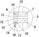
In the figure: 1. a motor body; 2. a connecting wire; 3. a protection mechanism; 4. an upper housing; 5. a lower housing; 6. a heat sink; 7. an upper connecting seat; 8. a lower connecting seat; 9. rotating the hole; 10. a rotating shaft; 11. a connecting rod; 12. placing holes; 13. a pin slot; 14. moving the hole; 15. moving the plate; 16. a pin rod; 17. a threaded rod; 18. a knob.
Detailed Description
The technical solutions in the embodiments of the present invention will be clearly and completely described below with reference to the drawings in the embodiments of the present invention, and it is obvious that the described embodiments are only a part of the embodiments of the present invention, and not all of the embodiments.
Referring to fig. 1-5, a direct current high temperature resistant motor comprises a motor body 1, a connecting wire 2 is arranged at the top of the motor body 1, a protection mechanism 3 is arranged on the motor body 1, the protection mechanism 3 comprises an upper shell 4 and a lower shell 5, the upper shell 4 is matched with the lower shell 5, upper connecting seats 7 are arranged at two sides of the bottom of the upper shell 4, lower connecting seats 8 are arranged at two sides of the top of the lower shell 5, a rotating hole 9 with one side being open is arranged at the top of the upper connecting seat 7, a connecting rod 11 is rotatably arranged in the rotating hole 9, a placing hole 12 with one side being open is arranged at the top of the lower connecting seat 8, the connecting rod 11 is matched with the placing hole 12, a pin groove 13 is arranged at the bottom of the lower connecting seat 8, a moving hole 14 is arranged at one side of the connecting rod 11, a moving plate 15 is slidably arranged in the moving hole 14, a pin rod 16 is arranged at the top of the moving plate 15, and the pin rod 16 is matched with the corresponding pin groove 13, install actuating mechanism in the removal hole 14, and actuating mechanism is connected with movable plate 15, because be equipped with protection machanism 3 on motor body 1, through the cooperation of knob 18, threaded rod 17, movable plate 15, pin rod 16 for pin rod 16 can block in the corresponding cotter way 13, and movable plate 15 can upwards extrude lower connecting seat 8, thereby can be to the firm fixed mounting on motor body 1 of upper casing 4 and lower casing 5.
In this embodiment, a plurality of fins 6 are all installed to the one side that last casing 4 and casing 5 kept away from each other down, through protection machanism 3, go up casing 4, casing 5 and fin 6's cooperation down, can improve the radiating efficiency of motor body 1 to improve motor body 1's high temperature resistance.
In this embodiment, the rotating shaft 10 is rotatably installed on the inner walls of the two sides of the rotating hole 9, the connecting rod 11 is fixedly sleeved on the rotating shaft 10, the driving mechanism comprises a threaded rod 17 rotatably installed in the moving hole 14, the knob 18 is installed at the bottom end of the threaded rod 17, the threaded rod 17 is sleeved with the moving plate 15 in a threaded manner, and the moving plate 15 is provided with the driving mechanism so that the moving plate 15 can move and fix the lower connecting seat 8.
In this embodiment, the inner walls of the two sides of the moving hole 14 are provided with limiting grooves, the two sides of the moving plate 15 are fixedly provided with limiting seats, and the limiting seats are slidably connected with the corresponding limiting grooves, so that the moving plate 15 can stably move.
In this embodiment, the inner wall of the bottom of the moving hole 14 is provided with a rotating hole, and the threaded rod 17 is rotatably connected to the rotating hole, so that the threaded rod 17 can be rotated stably by being provided with the rotating hole.
In the utility model, when the protection mechanism 3 is installed, the upper shell 4 and the lower shell 5 are installed on the motor body 1, so that the connecting rod 11 can be installed in the placing hole 12, the knob 18 can drive the threaded rod 17 to rotate by rotating the knob 18, the threaded rod 17 can drive the movable plate 15 and the pin rod 16 to move, the pin rod 16 can be clamped into the corresponding pin groove 13, and the movable plate 15 can upwards extrude the lower connecting seat 8, so that the upper shell 4 and the lower shell 5 can be stably and fixedly installed on the motor body 1;
because the motor body 1 is provided with the protection mechanism 3, the heat dissipation efficiency of the motor body 1 can be improved through the cooperation of the protection mechanism 3, the upper shell 4, the lower shell 5 and the heat dissipation fins 6, and therefore the high-temperature resistance of the motor body 1 is improved.
The above description is only for the preferred embodiment of the present invention, but the scope of the present invention is not limited thereto, and any person skilled in the art should be considered to be within the technical scope of the present invention, and equivalent alternatives or modifications according to the technical solution of the present invention and the inventive concept thereof should be covered by the scope of the present invention.
Claims (6)
1. A direct-current high-temperature-resistant motor comprises a motor body (1) and is characterized in that a connecting wire (2) is arranged at the top of the motor body (1), a protection mechanism (3) is arranged on the motor body (1), the protection mechanism (3) comprises an upper shell (4) and a lower shell (5), the upper shell (4) is matched with the lower shell (5), upper connecting seats (7) are respectively arranged on two sides of the bottom of the upper shell (4), lower connecting seats (8) are respectively arranged on two sides of the top of the lower shell (5), a rotating hole (9) with one open side is formed in the top of the upper connecting seat (7), a connecting rod (11) is rotatably arranged in the rotating hole (9), a placing hole (12) with one open side is formed in the top of the lower connecting seat (8), and the connecting rod (11) is matched with the placing hole (12), round pin groove (13) have been seted up to the bottom of lower connecting seat (8), removal hole (14) have been seted up to one side of connecting rod (11), slidable mounting has movable plate (15) in removal hole (14), pin rod (16) are installed at the top of movable plate (15), just pin rod (16) and corresponding round pin groove (13) looks adaptation, install actuating mechanism in removal hole (14), just actuating mechanism is connected with movable plate (15).
2. A direct current high temperature resistant motor according to claim 1, characterized in that a plurality of cooling fins (6) are installed on the side of the upper casing (4) and the lower casing (5) away from each other.
3. A dc high-temperature resistant motor according to claim 1, wherein the rotating shaft (10) is rotatably mounted on the inner wall of the rotating hole (9) at both sides, and the connecting rod (11) is fixedly sleeved on the rotating shaft (10).
4. The direct-current high-temperature-resistant motor is characterized in that the driving mechanism comprises a threaded rod (17) rotatably installed in the moving hole (14), a knob (18) is installed at the bottom end of the threaded rod (17), and the moving plate (15) is in threaded sleeve connection with the threaded rod (17).
5. The direct-current high-temperature-resistant motor according to claim 1, wherein the inner walls of the two sides of the moving hole (14) are provided with limiting grooves, the two sides of the moving plate (15) are both fixedly provided with limiting seats, and the limiting seats are slidably connected with the corresponding limiting grooves.
6. The direct-current high-temperature-resistant motor is characterized in that a rotating hole is formed in the inner wall of the bottom of the moving hole (14), and the threaded rod (17) is rotatably connected with the rotating hole.
Priority Applications (1)
| Application Number | Priority Date | Filing Date | Title |
|---|---|---|---|
| CN202121270960.1U CN215733760U (en) | 2021-06-08 | 2021-06-08 | Direct-current high-temperature-resistant motor |
Applications Claiming Priority (1)
| Application Number | Priority Date | Filing Date | Title |
|---|---|---|---|
| CN202121270960.1U CN215733760U (en) | 2021-06-08 | 2021-06-08 | Direct-current high-temperature-resistant motor |
Publications (1)
| Publication Number | Publication Date |
|---|---|
| CN215733760U true CN215733760U (en) | 2022-02-01 |
Family
ID=80041491
Family Applications (1)
| Application Number | Title | Priority Date | Filing Date |
|---|---|---|---|
| CN202121270960.1U Active CN215733760U (en) | 2021-06-08 | 2021-06-08 | Direct-current high-temperature-resistant motor |
Country Status (1)
| Country | Link |
|---|---|
| CN (1) | CN215733760U (en) |
-
2021
- 2021-06-08 CN CN202121270960.1U patent/CN215733760U/en active Active
Similar Documents
| Publication | Publication Date | Title |
|---|---|---|
| CN215733760U (en) | Direct-current high-temperature-resistant motor | |
| CN208862690U (en) | A kind of switched reluctance machines air-cooled radiating device | |
| CN214480100U (en) | External rotation type DC brushless motor | |
| CN215892205U (en) | Heat dissipation device for solar LED lamp | |
| CN213413538U (en) | Fill electric pile heat radiation structure | |
| CN212079990U (en) | Mechanical brake device for winding sheet | |
| CN218417055U (en) | Auxiliary heat dissipation device of electromechanical equipment | |
| CN211118319U (en) | Base platform type engine support | |
| CN208548809U (en) | A kind of heat radiating type integral motor | |
| CN217904168U (en) | Heat dissipation type motor with conveniently overhaul shell | |
| CN213094742U (en) | High-frequency power supply heat dissipation device | |
| CN218850526U (en) | Compact motor housing with good heat dissipation | |
| CN215378646U (en) | Novel adjustable radiating block motor for hydraulic engineering | |
| CN215643987U (en) | Lead-type power transformer convenient to radiate | |
| CN214134387U (en) | Flat cable welding device with heat dissipation device | |
| CN212968982U (en) | Energy-conserving bus duct of high security performance | |
| CN214316078U (en) | Power supply equipment with heat dissipation function | |
| CN221127241U (en) | Compact high-efficient photovoltaic radiator | |
| CN218648691U (en) | Large-flow cold air down-pressing type motor | |
| CN218124502U (en) | Heat pipe cooling device of motor | |
| CN206894424U (en) | A kind of direct current generator | |
| CN220874335U (en) | Three-phase multi-speed motor | |
| CN216872589U (en) | Intelligent comprehensive distribution box temperature control device | |
| CN109067059A (en) | A kind of flat wire machine winding and flat wire motor | |
| CN215258583U (en) | Generator convenient to installation |
Legal Events
| Date | Code | Title | Description |
|---|---|---|---|
| GR01 | Patent grant | ||
| GR01 | Patent grant |