CN215723896U - Fan equipment for fresh air system - Google Patents
Fan equipment for fresh air system Download PDFInfo
- Publication number
- CN215723896U CN215723896U CN202121356509.1U CN202121356509U CN215723896U CN 215723896 U CN215723896 U CN 215723896U CN 202121356509 U CN202121356509 U CN 202121356509U CN 215723896 U CN215723896 U CN 215723896U
- Authority
- CN
- China
- Prior art keywords
- air
- fan
- fixed
- indoor
- enclosure
- Prior art date
- Legal status (The legal status is an assumption and is not a legal conclusion. Google has not performed a legal analysis and makes no representation as to the accuracy of the status listed.)
- Active
Links
Images


Landscapes
- Filtering Of Dispersed Particles In Gases (AREA)
- Structures Of Non-Positive Displacement Pumps (AREA)
Abstract
The utility model discloses fan equipment for a fresh air system, which comprises a fan shield, wherein the upper ends of the surfaces of the two sides of the fan shield are fixedly sleeved with an outdoor air outlet and an indoor air outlet; the air blowing device provides power to absorb fresh air, the coarse filter screen plate in the coarse filter device can be used for filtering and dedusting, and then the coarse filter screen plate is cleaned regularly through a rolling brush, falling dust can fall from a dedusting groove through rotating a dedusting bottom plate, and is subjected to electrostatic adsorption through a plurality of series-connected electrostatic rods and fine filter screen plate filtration, so that the air entering a room is clean and dustless; the wind holes formed in the indoor mute air outlet through the pipelines form cyclone, and meanwhile, the mute cotton is matched for noise reduction and wind speed reduction.
Description
Technical Field
The utility model relates to the technical field of fan equipment, in particular to fan equipment for a fresh air system.
Background
The application of new trend system in present family air conditioning system is more and more favored by people, because of the lasting destruction of environment, present house ornamentation air conditioner is wall-hanging formula of induced drafting, it has harmful gas such as dust particle to directly absorb the external world through outer machine, then directly arrange indoor through interior machine, therefore, the damage of bringing is obvious, therefore, increase new trend system, through filter equipment, carry out filtration treatment with the outside air, simultaneously extrude the external world with gas such as indoor a large amount of carbon dioxide, and can carry out heat exchange treatment through fan equipment, reduce the power consumption loss, in addition, some new trend systems of appearance, because of not setting up the device of making an uproar, the noise that causes the fan passes to indoor and causes the sleep quality to descend, for this reason we propose a fan equipment that is used for new trend system and be used for solving above-mentioned problem.
SUMMERY OF THE UTILITY MODEL
The utility model aims to provide fan equipment for a fresh air system, which aims to solve the problems in the background technology.
In order to achieve the purpose, the utility model provides the following technical scheme: the utility model provides a fan equipment for new trend system, includes the fan guard shield, the fixed cover in fan guard shield both sides surface upper end has connect outdoor air exit and indoor air exit, the fixed cover in fan guard shield both sides surface bottom has connect outdoor inlet scoop and indoor silence air outlet, the equal fixed mounting of outdoor air exit, indoor air exit and outdoor inlet scoop port has the guard net, fixed mounting has the baffle between the fan guard shield inner wall, the baffle is fixed to be located between outdoor air exit and the indoor air exit, just fan guard shield inner chamber separates to be equipped with air exit, filter chamber, bottom fixed mounting heat exchanger plate in the air exit, bottom fixed mounting has air-blast device, rough filter, static stick and fine filter plate in the filter chamber, air-blast device both ends wind gap cup joints with rough filter device and outdoor inlet scoop are fixed respectively.
Preferably, the indoor silent air outlet comprises a pipeline, the outer surface of the pipeline conveying end is provided with an air hole, and silent cotton is adhered in the pipeline.
Preferably, the silencing cotton is provided with a plurality of wind tunnels and is in a shape of a rice.
Preferably, the air-blowing device is including first motor, the fixed air-blowing pump that is equipped with of first motor output, the fixed aspiration channel and the tuber pipe of having cup jointed of air-blowing pump, the aspiration channel is cup jointed with outdoor inlet scoop is fixed, the tuber pipe cup joints with rough filter device is fixed.
Preferably, the coarse filter device is including the second motor, the enclosure has been cup jointed in the activity of second motor output end, bottom fixed connection in enclosure bottom and the filter chamber, enclosure side surface cup joints with the play tuber pipe is fixed, the cross spout has been seted up to the enclosure side surface, the tooth's socket has been seted up to the enclosure inner wall of cross spout one side, the fixed gear that is equipped with of second motor output end, the gear is connected with the tooth's socket meshing, gear end face fixed connection round brush, enclosure opposite side surface fixed mounting has coarse filter plate, the round brush surface rotates the laminating with coarse filter plate side surface, the dust collecting tank has been seted up to the bottom in the filter chamber of enclosure bottom, and the dust collecting tank bottom rotates and is equipped with the dust removal bottom plate, dust removal bottom plate and the fixed inserted bar stop device that is equipped with of fan guard bottom surface.
Preferably, the number of the electrostatic rods is multiple, the electrostatic rods are connected in series and fixedly arranged between the rough filtering device and the fine filtering plate, and the heat exchange plate is fixedly arranged at the upper ends of the rough filtering device and the fine filtering plate.
Compared with the prior art, the utility model has the beneficial effects that:
1. when the fan device works, heat exchange treatment can be carried out on indoor exhaust air and sucked outdoor fresh air through the heat exchange plate, the temperature difference between the sucked fresh air and the indoor air is reduced, and the power consumption of the fan is reduced;
2. the air blowing device provides power to absorb fresh air, the coarse filter screen plate in the coarse filter device can be used for filtering and dedusting, and then the coarse filter screen plate is cleaned regularly through a rolling brush, falling dust can fall from a dedusting groove through rotating a dedusting bottom plate, and is subjected to electrostatic adsorption through a plurality of series-connected electrostatic rods and fine filter screen plate filtration, so that the air entering a room is clean and dustless;
3. the wind holes formed in the indoor mute air outlet through the pipelines form cyclone, and meanwhile, the mute cotton is matched for noise reduction and wind speed reduction.
Drawings
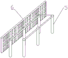
FIG. 1 is a schematic structural view of the present invention;
FIG. 2 is a schematic cross-sectional view of a fan shroud in accordance with the present invention;
FIG. 3 is a schematic view of the blower of the present invention;
FIG. 4 is a schematic view of a coarse filtration and dust removal device of the present invention;
FIG. 5 is a schematic view of a fine filtration device according to the present invention;
FIG. 6 is a schematic view of the indoor silent air outlet of the present invention;
in the figure: 1. a fan shroud; 11. an outdoor air outlet; 12. a protection net; 13. an outdoor air suction opening; 14. An indoor air outlet; 15. a partition plate; 16. an exhaust chamber; 17. a filtering chamber; 2. an indoor mute air outlet; 21. A pipeline; 22. a wind hole; 23. silent cotton; 3. a blower device; 31. a first motor; 32. a blast pump; 33. an air suction pipe; 34. an air outlet pipe; 4. a coarse filtration device; 41. a second motor; 42. a gear; 421. rolling and brushing; 43. a cross-shaped chute; 44. a tooth socket; 45. an enclosure; 46. a coarse filter screen plate; 47. a dust removal bottom plate; 48. An inserted link limiting device; 5. an electrostatic rod; 6. fine filter screen plate; 7. a heat exchange plate.
Detailed Description
The technical solutions in the embodiments of the present invention will be clearly and completely described below with reference to the drawings in the embodiments of the present invention, and it is obvious that the described embodiments are only a part of the embodiments of the present invention, and not all of the embodiments. All other embodiments, which can be derived by a person skilled in the art from the embodiments given herein without making any creative effort, shall fall within the protection scope of the present invention.
Referring to fig. 1-6, the present invention provides a technical solution: a fan device for a fresh air system comprises a fan shield 1, wherein an outdoor air outlet 11 and an indoor air outlet 14 are fixedly sleeved at the upper ends of the surfaces of two sides of the fan shield 1, an outdoor air inlet 13 and an indoor mute air outlet 2 are fixedly sleeved at the bottom ends of the surfaces of the two sides of the fan shield 1, the fan shield 1 is installed outdoors, fresh air is sucked through the outdoor air inlet 13 of the surface mounting at the outer side, the fresh air is purified by an internal purifying device and then is discharged indoors through the indoor mute air outlet 2, the indoor air is extruded by the fresh air, the air is discharged into the fan shield 1 from the indoor air outlet 14 of the surface of the fan shield 1 at the indoor side and then is discharged outdoors through the outdoor air outlet 11, and protective nets 12 are fixedly installed at the ports of the outdoor air outlet 11, the indoor air outlet 14 and the outdoor air inlet 13 and can effectively prevent larger objects from entering the fan shield 1, a partition board 15 is fixedly arranged between the inner walls of the fan shield 1, the partition board 15 is fixedly arranged between the outdoor air outlet 11 and the indoor air outlet 14, an air outlet chamber 16 and a filtering chamber 17 are arranged in the inner cavity of the fan shield 1 in a partitioning manner, the inner part of the fan shield 1 is divided into an upper part and a lower part by a clapboard 15, a heat exchange plate 7 is fixedly arranged on the inner bottom surface of the exhaust chamber 16, the heat exchange plate 7 can carry out heat exchange treatment on indoor exhaust air and fresh air, the temperature difference between the fresh air and the indoor air is reduced, the power consumption of the fan is reduced, the inner bottom surface of the filtering chamber 17 is fixedly provided with an air blowing device 3, a rough filtering device 4, an electrostatic rod 5 and a fine filtering screen plate 6, and air ports at two ends of the air blowing device 3 are fixedly sleeved with the rough filtering device 4 and the outdoor air suction port 13 respectively, the air blowing device 3 is used as a power source to absorb fresh air, and then the fresh air is filtered and dedusted through the rough filtering device 4, the electrostatic rod 5 and the fine filtering screen 6.
In one embodiment of the present invention, the indoor silent air outlet 2 includes a duct 21, an air hole 22 is formed on an outer surface of a conveying end of the duct 21, silent cotton 23 is adhered in the duct 21, wind in the duct 21 forms a cyclone through the air hole 22 to reduce wind noise, and the speed reduction and noise reduction treatment are performed through the silent cotton 23.
In one embodiment of the present invention, the silencing cotton 23 has a plurality of wind tunnels in a shape of a rice, and the silencing cotton 23 has a plurality of wind tunnels, so that the sound insulation treatment can be effectively performed.
As an embodiment of the present invention, the blower 3 includes a first motor 31, an air pump 32 is fixedly disposed at an output end of the first motor 31, an air suction pipe 33 and an air outlet pipe 34 are fixedly sleeved on the air pump 32, the air suction pipe 33 is fixedly sleeved on the outdoor air suction opening 13, the air outlet pipe 34 is fixedly sleeved on the coarse filter 4, and the first motor 31 drives the air pump 32 to rotate to generate centrifugal inlet air to increase air intake.
As an embodiment of the present invention, the coarse filtering device 4 includes a second motor 41, an output end of the second motor 41 is movably sleeved with an enclosure 45, a bottom end of the enclosure 45 is fixedly connected with the inner bottom surface of the filtering chamber 17, one side surface of the enclosure 45 is fixedly sleeved with an air outlet pipe 34, centrifugal air generated by the blower pump 32 enters the enclosure 45 through the air outlet pipe 34, a cross sliding chute 43 is formed on a side surface of the enclosure 45, a tooth space 44 is formed on an inner wall of the enclosure on one side of the cross sliding chute 43, a gear 42 is fixedly arranged at an output end of the second motor 41, the gear 42 is engaged with the tooth space 44, an end surface of the gear 42 is fixedly connected with a rolling brush 421, the output end of the second motor 41 penetrates through the enclosure 45 and drives the gear 42 to be engaged with the tooth space 44, so as to slide along the cross sliding chute 43 together with the rolling brush 421, a coarse filtering screen plate 46 is fixedly arranged on the other side surface of the enclosure 45, the laminating is rotated with coarse strainer plate 46 side surface to round brush 421 can regularly remove dust to coarse strainer plate 46 and handle, the dust removal groove has been seted up to the bottom surface in the filter chamber 17 of sealing cover 45 bottom, and the dust removal tank bottom rotates and is equipped with dust removal bottom plate 47, dust removal bottom plate 47 and the fixed inserted bar stop device 48 that is equipped with in fan guard shield 1 bottom surface, the dust that gets off by the clearance falls in the filter chamber 17 bottom of sealing cover 45 bottom department, opens inserted bar stop device 48 and rotates dust removal bottom plate 47, thereby the dust can be followed the dust removal inslot and fallen.
As an embodiment of the present invention, the number of the electrostatic rods 5 is plural, the electrostatic rods are connected in series and are fixedly arranged between the coarse filtering device 4 and the fine filtering plate 6, the heat exchange plate 7 is fixedly arranged at the upper ends of the coarse filtering device 4 and the fine filtering plate 6, fine dust still exists in the fresh air after coarse filtering, and the fresh air is electrostatically adsorbed by the plural series electrostatic rods 5 and is filtered by the fine filtering plate 6, so that the air entering the room is clean and dustless.
The working principle is as follows: the fan device is composed of a full-enclosed fan shield 1, an internal blowing device, a purifying device and an exhaust device, wherein the fan shield 1 is arranged outdoors, the internal blowing chamber 16 and the filter chamber 17 are separated by a clapboard 15, an outdoor suction inlet 13 is arranged on the outdoor surface of the fan shield 1 and can suck fresh air through a fixed sleeve joint with a suction pipe 33 of a blower pump 32, the fresh air enters an enclosure 45 in the filter chamber 17 through an air outlet pipe 34, then rough filtration and dust removal treatment are carried out through a rough filtration screen plate 46, when dust on the rough filtration screen plate 46 is more, maintenance is required regularly, an output end of a second motor 41 penetrates through the enclosure 45 and drives a gear 42 to be meshed with a tooth space 44, when an output shaft of the second motor 41 rotates, the gear 42 and a rolling brush 421 are driven to rotate, when the gear 42 rotates, the gear rolls along the tooth space 44 and slides along the cross groove 43, and the rolling brush 421 moves up and down along the cross groove 43 in the rotating process, therefore, the coarse filter screen plate 46 is thoroughly brushed, the rolling brush 421 can regularly perform dust removal treatment on the coarse filter screen plate 46, the cleaned dust falls on the inner bottom surface of the filter chamber 17 at the bottom end of the sealing cover 45, the inserted rod limiting device 48 is opened and the dust removal bottom plate 47 is rotated, so that the dust can fall from the dust removal tank, fine dust still exists in the fresh air after coarse filtration, the fresh air is electrostatically adsorbed by a plurality of electrostatic rods 5 in series connection and is filtered by the fine filter screen plate 6, so that the air exhausted into the room from the indoor silent air outlet 2 is clean and dustless, when the indoor air is extruded by more and more fresh air, the air is exhausted into the fan shield 1 from the indoor air outlet 14 on the surface of the fan shield 1 at the indoor side, the heat exchange treatment can be performed on the indoor exhaust air and the sucked outdoor fresh air through the heat exchange plate 7, and the temperature difference between the sucked fresh air and the indoor air is reduced, the power consumption of the fan is reduced, and the air is exhausted outdoors through the outdoor air outlet 11.
Although embodiments of the present invention have been shown and described, it will be appreciated by those skilled in the art that changes, modifications, substitutions and alterations can be made in these embodiments without departing from the principles and spirit of the utility model, the scope of which is defined in the appended claims and their equivalents.
Claims (6)
1. The utility model provides a fan equipment for new trend system, includes fan guard shield (1), its characterized in that, the fixed cover in fan guard shield (1) both sides surface upper end has connect outdoor air exit (11) and indoor air exit (14), the fixed cover in fan guard shield (1) both sides surface bottom has connect outdoor inlet scoop (13) and indoor silence air outlet (2), outdoor air exit (11), indoor air exit (14) and outdoor inlet scoop (13) port all fixed mounting have protecting net (12), fixed mounting has baffle (15) between fan guard shield (1) inner wall, baffle (15) are fixed to be located between outdoor air exit (11) and indoor air exit (14), just fan guard shield (1) inner chamber separates to be equipped with air discharge chamber (16), filter chamber (17), bottom fixed mounting heat transfer board (7) in air discharge chamber (16), the air-blowing device is characterized in that an air-blowing device (3), a rough filtering device (4), an electrostatic rod (5) and a fine filtering screen plate (6) are fixedly installed on the inner bottom surface of the filtering chamber (17), and air ports at two ends of the air-blowing device (3) are fixedly sleeved with the rough filtering device (4) and an outdoor air suction port (13) respectively.
2. A fan apparatus for a fresh air system as claimed in claim 1, wherein: the indoor mute air outlet (2) comprises a pipeline (21), an air hole (22) is formed in the outer surface of the conveying end of the pipeline (21), and mute cotton (23) is bonded in the pipeline (21).
3. A fan apparatus for a fresh air system as claimed in claim 2, wherein: the mute cotton (23) is provided with a plurality of wind tunnels and is in a shape of a rice.
4. A fan apparatus for a fresh air system as claimed in claim 1, wherein: blower device (3) are including first motor (31), first motor (31) output end is fixed and is equipped with air-blast pump (32), aspiration channel (33) and air-out pipe (34) have been cup jointed to air-blast pump (32) fixed, aspiration channel (33) and outdoor inlet scoop (13) are fixed to be cup jointed, air-out pipe (34) and coarse filter device (4) are fixed to be cup jointed.
5. A fan apparatus for a fresh air system according to claim 4, wherein: rough filter device (4) including second motor (41), the enclosure (45) has been cup jointed in the activity of second motor (41) output, enclosure (45) bottom and filter chamber (17) interior bottom fixed connection, enclosure (45) side surface and play tuber pipe (34) fixed cup joint, cross spout (43) have been seted up to enclosure (45) side surface, tooth's socket (44) have been seted up to enclosure (45) inner wall of cross spout (43) one side, second motor (41) output end is fixed and is equipped with gear (42), gear (42) are connected with tooth's socket (44) meshing, gear (42) terminal surface fixed connection round brush (421), enclosure (45) opposite side surface fixed mounting has coarse filter screen board (46), round brush (421) surface rotates with coarse filter screen board (46) side surface and laminates, the dust removal groove has been seted up to the bottom surface in filter chamber (17) of enclosure (45) bottom, and a dust removal bottom plate (47) is rotatably arranged at the bottom of the dust removal groove, and an inserted rod limiting device (48) is fixedly arranged on the bottom surfaces of the dust removal bottom plate (47) and the fan shield (1).
6. A fan apparatus for a fresh air system as claimed in claim 1, wherein: the number of the electrostatic rods (5) is multiple, the electrostatic rods are connected in series and fixedly arranged between the coarse filtering device (4) and the fine filtering screen plate (6), and the heat exchange plate (7) is fixedly arranged at the upper ends of the coarse filtering device (4) and the fine filtering screen plate (6).
Priority Applications (1)
| Application Number | Priority Date | Filing Date | Title |
|---|---|---|---|
| CN202121356509.1U CN215723896U (en) | 2021-06-18 | 2021-06-18 | Fan equipment for fresh air system |
Applications Claiming Priority (1)
| Application Number | Priority Date | Filing Date | Title |
|---|---|---|---|
| CN202121356509.1U CN215723896U (en) | 2021-06-18 | 2021-06-18 | Fan equipment for fresh air system |
Publications (1)
| Publication Number | Publication Date |
|---|---|
| CN215723896U true CN215723896U (en) | 2022-02-01 |
Family
ID=80043320
Family Applications (1)
| Application Number | Title | Priority Date | Filing Date |
|---|---|---|---|
| CN202121356509.1U Active CN215723896U (en) | 2021-06-18 | 2021-06-18 | Fan equipment for fresh air system |
Country Status (1)
| Country | Link |
|---|---|
| CN (1) | CN215723896U (en) |
Cited By (1)
| Publication number | Priority date | Publication date | Assignee | Title |
|---|---|---|---|---|
| CN117847668A (en) * | 2023-12-29 | 2024-04-09 | 翔嘉环境科技(江苏)有限公司 | Ventilating duct with dust removal filtering structure |
-
2021
- 2021-06-18 CN CN202121356509.1U patent/CN215723896U/en active Active
Cited By (1)
| Publication number | Priority date | Publication date | Assignee | Title |
|---|---|---|---|---|
| CN117847668A (en) * | 2023-12-29 | 2024-04-09 | 翔嘉环境科技(江苏)有限公司 | Ventilating duct with dust removal filtering structure |
Similar Documents
| Publication | Publication Date | Title |
|---|---|---|
| CN104174236B (en) | The air cleaner of paint locker and carpentry yard | |
| CN104998501B (en) | The air filter unit that a kind of paint locker or carpentry yard use | |
| CN215723896U (en) | Fan equipment for fresh air system | |
| CN108979699A (en) | A kind of ventilating system of tunnel dust removal by filtration | |
| CN109442616A (en) | A kind of air cleaning facility for smart home based on Internet of Things | |
| CN106016491A (en) | Dust-removal air regulation device | |
| CN208365607U (en) | A kind of super-silent side-suction type range hood | |
| CN204388249U (en) | A kind of New indoor wind purification device | |
| CN207716597U (en) | A kind of ventilation equipment for building with cleaning function | |
| CN207756567U (en) | A kind of Airshower chamber | |
| CN110215789A (en) | Workshop environmental protection dust collecting equipment | |
| CN212418935U (en) | Dust removal device between locomotive machinery | |
| CN216278692U (en) | Fire-fighting and smoke-discharging dual-purpose ventilator | |
| CN205897358U (en) | Dust removal air conditioning equipment | |
| CN206501012U (en) | New polishing dust collection and purification system | |
| CN204786769U (en) | System for energy -conserving new trend PM2. 5 integration air condition | |
| CN209155336U (en) | Air cleaning unit in a kind of architectural environment | |
| CN208504590U (en) | A kind of fresh air system | |
| CN207702598U (en) | A kind of external cleans the aircleaning facility of closed binary cycle system | |
| CN206997242U (en) | A kind of multi-functional Airshower chamber | |
| CN204933158U (en) | A kind of through type two-stage dust removal device | |
| CN206028256U (en) | Simple structure's wind leaching rooms | |
| CN106540790A (en) | A kind of powdery paints interior circulation milling dedusting cooling system | |
| CN220532463U (en) | High-efficient dust removal purification wind shower | |
| CN109140617A (en) | A kind of clean operating room low noise air supply device |
Legal Events
| Date | Code | Title | Description |
|---|---|---|---|
| GR01 | Patent grant | ||
| GR01 | Patent grant |