CN215700733U - Polishing device with recycling structure for vacuum cup production - Google Patents
Polishing device with recycling structure for vacuum cup production Download PDFInfo
- Publication number
- CN215700733U CN215700733U CN202122119877.0U CN202122119877U CN215700733U CN 215700733 U CN215700733 U CN 215700733U CN 202122119877 U CN202122119877 U CN 202122119877U CN 215700733 U CN215700733 U CN 215700733U
- Authority
- CN
- China
- Prior art keywords
- rotating shaft
- motor
- polishing device
- fan
- atomizing
- Prior art date
- Legal status (The legal status is an assumption and is not a legal conclusion. Google has not performed a legal analysis and makes no representation as to the accuracy of the status listed.)
- Active
Links
Images


Abstract
The utility model discloses a polishing device with a recycling structure for producing a vacuum cup, which comprises a processing table and a telescopic cylinder, wherein a supporting plate is welded and connected above the processing table, a cross beam is arranged above the supporting plate, a dust collecting funnel is arranged below the processing table, a round pipe is connected below the dust collecting funnel, a fan is arranged on the left side of the round pipe, a dust collecting box is arranged on the left side of the fan, a second motor is arranged above an installation plate, a crawler belt is connected to the outside of the second motor, and a second rotating shaft is connected to the inside of the crawler belt. This thermos cup production is with burnishing device who has recovery structure passes through the setting of collection dirt funnel, pipe, fan and dust collection box, and the fan link up each other through the pipe with collection dirt funnel, and collection dirt funnel installs under the cylinder, and suction through the fan makes collection dirt funnel inhale the waste material, and the dust collection box is discharged into through the pipe, and the dust can be avoided to the collection dirt function, and the reduction equipment wearing and tearing to save fund.
Description
Technical Field
The utility model relates to the technical field of production of vacuum cups, in particular to a polishing device with a recycling structure for production of a vacuum cup.
Background
A Vacuum cup (Vacuum cup) is a container for containing water, which is generally made of ceramic or stainless steel and a Vacuum layer, and the production and processing of the Vacuum cup requires polishing operation, which is one of surface modification techniques, and generally refers to a processing method for changing the physical properties of the surface of a material by friction with a rough object (sand paper containing particles with higher hardness, etc.), and the purpose of the processing method is to obtain a specific surface roughness.
The polishing device with the recycling structure for producing the vacuum cups in the market does not have the functions of cleaning and cooling, can lead to the fact that the machine is accumulated because of the chips that lead to polishing and causes mechanical damage and mechanical damage that the machine is overheated to cause for a long time to work, can not be fine satisfy people's user demand, to the above-mentioned condition, carry out technical innovation on current burnishing machine basis.
SUMMERY OF THE UTILITY MODEL
The utility model aims to provide a polishing device with a recycling structure for vacuum cup production, and aims to solve the problems that the polishing device with the recycling structure for vacuum cup production provided in the background art does not have cleaning and cooling functions, so that mechanical damage is caused by debris accumulation of a machine due to polishing and mechanical damage is caused by long-time working overheat of the machine, the use requirements of people cannot be well met, and the use of the machine is influenced.
In order to achieve the purpose, the utility model provides the following technical scheme: a polishing device with a recycling structure for producing a vacuum cup comprises a processing table and a telescopic cylinder, wherein a supporting plate is welded above the processing table, a cross beam is arranged above the supporting plate, a dust collecting funnel is arranged below the processing table, a round pipe is connected below the dust collecting funnel, a fan is arranged on the left side of the round pipe, a dust collecting box is arranged on the left side of the fan, a first motor is fixedly connected to the outer portion of the supporting plate, a first rotating shaft is connected to the outer portion of the first motor, a fixing frame is connected to the outer portion of the first rotating shaft, a roller is arranged on the right side of the fixing frame, the telescopic cylinder is arranged above the cross beam, a telescopic rod is arranged below the cross beam, an installation plate is welded below the telescopic rod, a second motor is arranged above the installation plate, a crawler belt is connected to the outer portion of the second motor, and a second rotating shaft is connected to the inner portion of the crawler belt, and the left end of the second rotating shaft is connected with a polishing roller.
Preferably, the externally mounted of backup pad has the atomization component who is used for atomizing, and atomization component is including atomizing shell, damping pivot and atomizer, the outer end of atomizing shell rotates and is connected with the damping pivot, and the externally mounted of atomizing shell has atomizer.
Preferably, the first rotating shaft is rotatably connected with the roller, and the outer wall of the first rotating shaft is attached to the inner wall of the roller.
Preferably, a motor shaft of the second motor is in transmission connection with the second rotating shaft through a crawler belt, and the right end of the second rotating shaft is connected with a connecting block.
Preferably, the second motor and the mounting plate are horizontally distributed, and the second motor is symmetrically distributed with two motors along the center line of the mounting plate.
Preferably, the fan and the dust collecting funnel are communicated with each other through a circular tube, and the dust collecting funnel is in sealing connection with the circular tube.
Preferably, the number of the fixing frames is two along the center line of the processing table, and the fixing frames are square.
Compared with the prior art, the utility model has the beneficial effects that: adopt collection dirt and atomizing subassembly, the suction through the fan makes collection dirt funnel inhale the waste material, discharges into the dust collection box through the pipe, reaches clear effect, and atomizing subassembly is used for handling the mechanical damage that the machine leads to because of overheated to save the fund.
According to the dust collection device, the dust collection funnel, the round pipe, the fan and the dust collection box are arranged, the fan and the dust collection funnel are communicated with each other through the round pipe, the dust collection funnel is arranged under the roller, waste materials are sucked into the dust collection funnel through the suction force of the fan and are discharged into the dust collection box through the round pipe, dust can be avoided through the dust collection function, the safety is improved, the visibility of a workplace is improved, the abrasion of equipment is reduced, and therefore funds are saved.
According to the utility model, through the arrangement of the atomizing shell, the damping rotating shaft and the atomizing nozzle, the angle of the atomizing nozzle can be adjusted through the rotation of the damping rotating shaft, so that multidirectional spraying is achieved, the damage of the machine caused by overheating of the machine can be reduced by the atomizing assembly, and thus the fund is saved.
According to the utility model, through the arrangement of the telescopic cylinder and the telescopic rod, the telescopic cylinder is arranged at the central position of the cross beam, the telescopic rod is pushed through the movement of the telescopic cylinder, then the telescopic rod drives the polishing roller controlled by the motor to move up and down, and the telescopic device can realize the polishing work of the vacuum cup with multiple sizes.
Drawings
FIG. 1 is a schematic front view of a polishing device with a recycling structure for producing a vacuum cup according to the present invention;
FIG. 2 is a schematic view of a top view of a polishing apparatus with a recycling structure for producing a vacuum cup according to the present invention;
FIG. 3 is an enlarged schematic view of the polishing device with a recycling structure for vacuum cup production in FIG. 1;
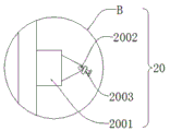
FIG. 4 is an enlarged schematic view of a polishing device with a recycling structure for producing a vacuum cup shown in FIG. 1 at B.
In the figure: 1. a processing table; 2. a support plate; 3. a cross beam; 4. a dust collecting funnel; 5. a circular tube; 6. a fan; 7. a dust collection box; 8. a first motor; 9. a first rotating shaft; 10. a fixed mount; 11. a drum; 12. a telescopic cylinder; 13. a telescopic rod; 14. mounting a plate; 15. a second motor; 16. a crawler belt; 17. a second rotating shaft; 18. polishing the roller; 19. connecting blocks; 20. an atomizing assembly; 2001. an atomizing shell; 2002. a damping rotating shaft; 2003. an atomizing spray head.
Detailed Description
As shown in fig. 1-2, a polishing device with a recycling structure for vacuum cup production comprises a processing table 1 and a telescopic cylinder 12, wherein a supporting plate 2 is welded above the processing table 1, a beam 3 is installed above the supporting plate 2, a dust collecting funnel 4 is installed below the processing table 1, a round tube 5 is connected below the dust collecting funnel 4, a fan 6 is installed on the left side of the round tube 5, a dust collecting box 7 is installed on the left side of the fan 6, the fan 6 and the dust collecting funnel 4 are communicated with each other through the round tube 5, the dust collecting funnel 4 is hermetically connected with the round tube 5, through the arrangement of the dust collecting funnel 4, the round tube 5, the fan 6 and the dust collecting box 7, the fan 6 and the dust collecting funnel 4 are communicated with each other through the round tube 5, the dust collecting funnel 4 is installed under a roller 11, waste is sucked by the dust collecting funnel 4 through the suction force of the fan 6 and is discharged into the dust collecting box 7 through the round tube 5, the dust collection function can avoid dust, the safety is improved, the visibility of a workplace is improved, the abrasion of equipment is reduced, and therefore the fund is saved, the first motor 8 is fixedly connected to the outer portion of the supporting plate 2, the first motor 8 is connected to the outer portion of the first motor 9, the fixing frame 10 is connected to the outer portion of the first motor 9, the roller 11 is installed on the right side of the fixing frame 10, the two fixing frames 10 are symmetrically arranged along the central line of the processing table 1, the fixing frame 10 is square, the first rotating shaft 9 is rotatably connected with the roller 11, the outer wall of the first rotating shaft 9 is attached to the inner wall of the roller 11, the telescopic cylinder 12 is installed above the cross beam 3, the telescopic rod 13 is installed below the cross beam 3, the installation plate 14 is welded below the telescopic rod 13, the telescopic cylinder 12 is installed at the central position of the cross beam 3 through the arrangement of the telescopic cylinder 12 and the telescopic rod 13, the telescopic cylinder 12 pushes the telescopic rod 13 through the movement of the telescopic cylinder 12, the telescopic link 13 drives the polishing roller 18 controlled by the second motor 15 to move up and down, and the telescopic device is convenient for polishing workpieces with different sizes, so that polishing work of more types of metal can be realized.
Referring to fig. 3, a second motor 15 is installed above the mounting plate 14, a caterpillar band 16 is connected to the outside of the second motor 15, the second motor 15 and the mounting plate 14 are horizontally distributed, two second motors 15 are symmetrically distributed along the center line of the mounting plate 14, a second rotating shaft 17 is connected to the inside of the caterpillar band 16, a polishing roller 18 is connected to the left end of the second rotating shaft 17, a motor shaft of the second motor 15 is in transmission connection with the second rotating shaft 17 through the caterpillar band 16, and a connecting block 19 is connected to the right end of the second rotating shaft 17.
Referring to fig. 4, an atomizing assembly 20 for atomizing is mounted outside the supporting plate 2, the atomizing assembly 20 includes an atomizing shell 2001, a damping rotating shaft 2002 and an atomizing nozzle 2003, the damping rotating shaft 2002 is rotatably connected to an outer end of the atomizing shell 2001, the atomizing nozzle 2003 is mounted outside the atomizing shell 2001, and by the arrangement of the atomizing shell 2001, the damping rotating shaft 2002 and the atomizing nozzle 2003, the angle of the atomizing nozzle 2003 can be adjusted through the rotation of the damping rotating shaft 2002, so that multi-directional spraying is achieved, the atomizing assembly 20 can reduce machine damage caused by overheating of a machine, and accordingly, money is saved.
In conclusion, when the polishing device with the recycling structure for producing the vacuum cup is used, the first motor 8 is started firstly, the roller 11 attached to the first rotating shaft 9 is driven to rotate through the rotation of the output end of the first motor 8, the rotation directions of the output ends of the first motors 8 on the two sides are opposite, so that the effect of clamping the vacuum cup can be achieved, then the second motor 15 is started, the crawler belt 16 connected with the second motor 15 and the second rotating shaft 17 drives the grinding roller 18 to rotate through the rotation of the second motor 15, the telescopic cylinder 12 is started accordingly, the telescopic rod 13 is pushed through the movement of the telescopic cylinder 12, then the telescopic rod 13 drives the grinding roller 18 controlled by the second motor 15 to move up and down, the telescopic device is convenient for grinding vacuum cups with different sizes, finally the atomizing assembly 20 is started, the angle of the atomizing nozzle 2003 can be adjusted through the rotation of the damping rotating shaft 2002, reach diversified spraying, atomizing component 20 can reduce the machine and damage because of overheated and lead to save the fund, when needs are clean, starts fan 6, and suction through fan 6 makes collection dirt funnel 4 inhale the waste material, discharges into dust collection box 7 through pipe 5, and the dust can be avoided to the collection dirt function, improves the security, improves workplace's visibility, reduces equipment wear, thereby saves the fund.
Claims (7)
1. The polishing device with the recycling structure for the production of the vacuum cup comprises a processing table (1) and a telescopic cylinder (12), and is characterized in that a supporting plate (2) is welded to the upper portion of the processing table (1), a beam (3) is installed above the supporting plate (2), a dust collecting funnel (4) is installed below the processing table (1), a round pipe (5) is connected below the dust collecting funnel (4), a fan (6) is installed on the left side of the round pipe (5), a dust collecting box (7) is installed on the left side of the fan (6), a first motor (8) is fixedly connected to the outer portion of the supporting plate (2), a first rotating shaft (9) is connected to the outer portion of the first motor (8), a fixing frame (10) is connected to the outer portion of the first rotating shaft (9), a roller (11) is installed on the right side of the fixing frame (10), the telescopic cylinder (12) is installed above the beam (3), telescopic link (13) are installed to the below of crossbeam (3), and the below welded connection of telescopic link (13) has mounting panel (14), second motor (15) are installed to the top of mounting panel (14), and the external connection of second motor (15) has track (16), the internal connection of track (16) has second pivot (17), and the left end of second pivot (17) is connected with grinding roller (18).
2. A thermos cup production polishing device with a recycling structure according to claim 1, characterized in that an atomizing assembly (20) for atomizing is installed outside the supporting plate (2), and the atomizing assembly (20) comprises an atomizing shell (2001), a damping rotating shaft (2002) and an atomizing nozzle (2003), the outer end of the atomizing shell (2001) is rotatably connected with the damping rotating shaft (2002), and the atomizing nozzle (2003) is installed outside the atomizing shell (2001).
3. A polishing device with a recycling structure for thermos cup production according to claim 1, characterized in that the first rotating shaft (9) is rotatably connected with the roller (11), and the outer wall of the first rotating shaft (9) is attached to the inner wall of the roller (11).
4. A thermos cup production polishing device with a recycling structure according to claim 1, characterized in that a motor shaft of the second motor (15) is in transmission connection with the second rotating shaft (17) through a crawler belt (16), and a connecting block (19) is connected to the right end of the second rotating shaft (17).
5. A thermos cup production polishing device with a recycling structure according to claim 1, characterized in that the second motor (15) and the mounting plate (14) are horizontally distributed, and two second motors (15) are symmetrically distributed along the center line of the mounting plate (14).
6. A polishing device with a recycling structure for thermos cup production according to claim 1, characterized in that the blower (6) and the dust collection funnel (4) are communicated with each other through a circular tube (5), and the dust collection funnel (4) is hermetically connected with the circular tube (5).
7. A polishing device with a recycling structure for thermos cup production according to claim 1, characterized in that the number of the fixing frames (10) is two along the center line of the processing table (1), and the fixing frames (10) are rectangular.
Priority Applications (1)
| Application Number | Priority Date | Filing Date | Title |
|---|---|---|---|
| CN202122119877.0U CN215700733U (en) | 2021-09-03 | 2021-09-03 | Polishing device with recycling structure for vacuum cup production |
Applications Claiming Priority (1)
| Application Number | Priority Date | Filing Date | Title |
|---|---|---|---|
| CN202122119877.0U CN215700733U (en) | 2021-09-03 | 2021-09-03 | Polishing device with recycling structure for vacuum cup production |
Publications (1)
| Publication Number | Publication Date |
|---|---|
| CN215700733U true CN215700733U (en) | 2022-02-01 |
Family
ID=80014226
Family Applications (1)
| Application Number | Title | Priority Date | Filing Date |
|---|---|---|---|
| CN202122119877.0U Active CN215700733U (en) | 2021-09-03 | 2021-09-03 | Polishing device with recycling structure for vacuum cup production |
Country Status (1)
| Country | Link |
|---|---|
| CN (1) | CN215700733U (en) |
Cited By (1)
| Publication number | Priority date | Publication date | Assignee | Title |
|---|---|---|---|---|
| CN116442104A (en) * | 2023-06-13 | 2023-07-18 | 山东宇航航空科技有限公司 | Gravure printing cylinder chromium coating polishing machine |
-
2021
- 2021-09-03 CN CN202122119877.0U patent/CN215700733U/en active Active
Cited By (2)
| Publication number | Priority date | Publication date | Assignee | Title |
|---|---|---|---|---|
| CN116442104A (en) * | 2023-06-13 | 2023-07-18 | 山东宇航航空科技有限公司 | Gravure printing cylinder chromium coating polishing machine |
| CN116442104B (en) * | 2023-06-13 | 2023-09-08 | 山东宇航航空科技有限公司 | Gravure printing cylinder chromium coating polishing machine |
Similar Documents
| Publication | Publication Date | Title |
|---|---|---|
| CN210938561U (en) | Grinding machine with function is collected to iron fillings | |
| CN215700733U (en) | Polishing device with recycling structure for vacuum cup production | |
| CN108994709A (en) | A kind of construction is quickly polished derusting device with steel plate | |
| CN210678174U (en) | Grinding machine piece collection device | |
| CN209548938U (en) | A kind of grinding machine air cleaning unit | |
| CN211867336U (en) | A sweep ray apparatus for cell-phone tempering membrane | |
| CN215297245U (en) | Magnetic particle flaw detector with shockproof function | |
| CN109176288A (en) | A kind of building wall polishing machine | |
| CN213004527U (en) | Mechanical parts polishing equipment with from clear structure | |
| CN211388265U (en) | Portable self-adaptation pipe diameter inner chamber burnishing device of metal seamless pipe | |
| CN215239781U (en) | Polishing device for machining steel member | |
| CN218556588U (en) | Guide pillar polisher for gas detector shell injection mold | |
| CN207616273U (en) | A kind of tire flour milling machine | |
| CN217493623U (en) | Dust-free grinding machine for grinding metal materials | |
| CN219310861U (en) | Panel lacquer painting polisher | |
| CN210879248U (en) | Machining grinder | |
| CN217914486U (en) | Grinding and polishing machine for processing jade finished product | |
| CN211219984U (en) | Edge grinding machine suitable for tableware processing | |
| CN111941239A (en) | Plate rust removal device | |
| CN210209807U (en) | Electromechanical accessory polisher | |
| CN220145368U (en) | Material collecting box of numerical control machine tool | |
| CN218643145U (en) | Pavement marking removing device | |
| CN219444755U (en) | Metal part surface machining polishing mechanism | |
| CN212886623U (en) | Stainless steel band surface grinding device | |
| CN219005590U (en) | Grinding device is used in mould steel production |
Legal Events
| Date | Code | Title | Description |
|---|---|---|---|
| GR01 | Patent grant | ||
| GR01 | Patent grant |