CN215685712U - Dining cabinet convenient to use - Google Patents
Dining cabinet convenient to use Download PDFInfo
- Publication number
- CN215685712U CN215685712U CN202122085859.5U CN202122085859U CN215685712U CN 215685712 U CN215685712 U CN 215685712U CN 202122085859 U CN202122085859 U CN 202122085859U CN 215685712 U CN215685712 U CN 215685712U
- Authority
- CN
- China
- Prior art keywords
- plate
- bottom plate
- plates
- dining
- sides
- Prior art date
- Legal status (The legal status is an assumption and is not a legal conclusion. Google has not performed a legal analysis and makes no representation as to the accuracy of the status listed.)
- Active
Links
Images


Abstract
The utility model discloses a dining cabinet convenient to use, and relates to the field of dining cabinets, which comprises a bottom plate and two groups of sliding groove strips, wherein two sides of the top of the bottom plate are provided with side plates, the tops of the side plates are provided with top plates, the middle of the top of the bottom plate is provided with a middle plate, the tops of the top plates are connected with the top plates, back plates are arranged on the back surfaces of the top plates and the bottom plate, the top of the bottom plate is positioned between one side plate and the middle plate and is provided with a partition plate, the surface, close to the middle plate, of the inner side surface of the other side plate is provided with a group of mutually matched slots, a layer plate is arranged between every two matched slots, and the top of each layer plate is rotatably provided with a group of rotating plates. According to the utility model, the cabinet is integrally designed into a modular design combining the bottom plate, the top plate, the side plates, the back plate and the middle plate, so that the disassembled modular parts can be transported and then assembled at a required place when required, and the transportation is more convenient.
Description
Technical Field
The utility model relates to the field of dining cabinets, in particular to a dining cabinet convenient to use.
Background
The cupboard is a storage cupboard which is placed in the vacant place of a dining room or at one side of a dining table and has a storage function, and can be used for placing bowls, dishes, chopsticks, wine, beverages, temporarily placing soup and dishes, and also can be used for placing small articles wrapped by guests.
The existing dining cabinet is generally of an integral structure, and the cabinet body is generally separated into small cabinets.
But overall structure's cupboard occupation space is big during the transportation, and when the tableware of putting in single cabinet body was more, the tableware that leans on in was not convenient for take out, and the mode of depositing of red wine and white spirit is different, and red wine need transversely place, and is inconvenient to use.
Disclosure of Invention
Based on the above, the utility model aims to provide a dining cabinet convenient to use, so as to solve the technical problems that the existing dining cabinet is inconvenient to transport and use.
In order to achieve the purpose, the utility model provides the following technical scheme: a dining cabinet convenient to use comprises a bottom plate and two groups of chute strips, wherein two sides of the top of the bottom plate are provided with side plates, the tops of the side plates are provided with a top plate, the middle of the top of the bottom plate is provided with a middle plate, the tops of the top plate and the bottom plate are provided with back plates, the top of the bottom plate is positioned between one side plate and the middle plate and is provided with a partition plate, the inner side surface of the other side plate close to the middle plate is provided with a group of mutually matched slots, a laminate is arranged between every two matched slots, the top of each laminate is rotatably provided with a group of rotating plates, the inner sides of the side plates close to the partition plate and the side surface of the partition plate close to the side plate are provided with a plurality of groups of placing blocks, the other side surface of the partition plate and the side surface of the middle plate close to the partition plate are provided with a plurality of placing blocks, and the inner sides of the two groups of the chute strips are connected with guide slide strips in a sliding manner, a red wine storage rack is arranged between one group of the guide sliding strips, and a white wine and beverage storage rack is arranged between the other group of the guide sliding strips.
Through adopting above-mentioned technical scheme, the cabinet body can be made up into with the backplate to bottom plate, curb plate, roof, intermediate lamella, and the installation of the plywood of can being convenient for to the fluting, and the access of the rotatory tableware of can being convenient for of rotor plate takes the piece and can be convenient for place the draw runner, and the slip of red wine storage rack and white spirit and beverage storage rack can be restricted to the direction draw runner, and the red wine storage rack is used for transversely depositing red wine and prevents that red wine from rolling, and white spirit and beverage storage rack are used for depositing white spirit or beverage.
The utility model is further provided with support legs at four corners and in the middle of the bottom plate, and the tail ends of the upper surface and the lower surface of the guide sliding strip are respectively provided with a limiting sliding block in the sliding groove strip.
Through adopting above-mentioned technical scheme, bottom plate bottom four corners and centre all set up the stabilizer blade and can make the device more firm, and spacing slider can prevent that the direction draw runner from breaking away from the chute strip.
The utility model is further provided that the outer sides of the rotating plates are provided with annular sliding blocks, and the laminates are internally provided with annular sliding grooves matched with the annular sliding blocks.
Through adopting above-mentioned technical scheme, annular slider can restrict the rotor plate rotation with the cooperation of annular spout.
The utility model is further provided that the corners of the placing block are all provided with jacks, and both ends of the sliding groove strip are both provided with jacks matched with the jacks on the placing block.
Through adopting above-mentioned technical scheme, the jack cooperation of putting the jack on the piece and the jack on the spout strip can be convenient for the fixed of spout strip.
The utility model is further arranged in such a way that the front surfaces of the bottom plate and the top plate are rotatably connected with two groups of cabinet doors, and the two groups of cabinet doors are respectively positioned at two sides of the middle plate.
By adopting the technical scheme, the cabinet door can be opened and closed.
In summary, the utility model mainly has the following beneficial effects:
1. according to the utility model, the cabinet is integrally designed into a modular design combining the bottom plate, the top plate, the side plates, the back plate and the middle plate, so that the disassembled modular parts can be transported and then assembled at a required place when required, and the transportation is more convenient;
2. according to the utility model, the set of the layer plates are arranged on one side separated by the middle plate in the cabinet body, the rotating plate is rotatably connected on the layer plates, tableware can be placed on the rotating plate, when the rear tableware is needed, the rotating plate can be taken out only by rotating the rotating plate, the other side separated by the middle plate in the cabinet body is separated by the partition plate, the placing blocks are arranged in the separated spaces, the red wine storage rack or the white wine and beverage storage rack is slidably connected in the chute strips through the guide sliding strips, the chute strips connected with the red wine storage rack or the white wine and beverage storage rack can be placed on the placing blocks according to the needs, and then the red wine or the white wine is respectively stored, so that the convenience is further realized.
Drawings
FIG. 1 is a partial cross-sectional view of the interior of the present invention;
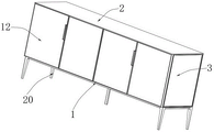
FIG. 2 is a front view of the present invention;
FIG. 3 is an enlarged view of A of FIG. 1 according to the present invention;
FIG. 4 is an enlarged view of B of FIG. 1 in accordance with the present invention;
FIG. 5 is a top view of the landing block of the present invention;
fig. 6 is a schematic structural diagram of the present invention.
In the figure: 1. a base plate; 2. a top plate; 3. a side plate; 4. a back plate; 5. a middle plate; 6. a partition plate; 7. laminating the board; 8. grooving; 9. a rotating plate; 10. an annular chute; 11. an annular slider; 12. a cabinet door; 13. setting blocks; 14. a jack; 15. a chute bar; 16. a guide slider; 17. a limiting slide block; 18. a red wine storage rack; 19. a white spirit and beverage storage rack; 20. and (3) a support leg.
Detailed Description
The technical solution in the embodiments of the present invention will be clearly and completely described below with reference to the accompanying drawings in the embodiments of the present invention. The embodiments described below with reference to the accompanying drawings are illustrative only for the purpose of explaining the present invention, and are not to be construed as limiting the present invention.
The following describes an embodiment of the present invention based on its overall structure.
A dining cabinet convenient to use is disclosed, as shown in figures 1-6, comprising a bottom plate 1 and two sets of chute strips 15, side plates 3 are arranged on two sides of the top of the bottom plate 1, a top plate 2 is arranged on the top of the side plates 3, a middle plate 5 connected with the top plate 2 is arranged in the middle of the top of the bottom plate 1, a back plate 4 is arranged on the back of the top plate 2 and the back of the bottom plate 1, the side plates 3, the top plate 2, the middle plate 5 and the back plate 4 can be combined into a cabinet body, a partition plate 6 is arranged in the middle of one side plate 3 and the middle plate 5 at the top of the bottom plate 1, a set of mutually matched slots 8 are arranged on the inner side surface of the other side plate 3 close to the middle plate 5, installation of the corresponding plate 7 can be facilitated, a laminated plate 7 is arranged between every two matched slots 8, a set of rotating plate 9 is arranged on the top of each laminated plate 7 in a rotating manner, tableware can be facilitated by rotating the rotating of the rotating plate 9, a plurality of sets of overlapping blocks 13 are arranged on the inner side plate 3 of the partition plate 6 and on the side surface of the partition plate 6 close to one side plate 3 close to one side plate 6 close to one side plate 3 And the other side of the partition board 6 and one side of the intermediate board 5 close to the partition board 6 are provided with a plurality of groups of placing blocks 13, the placing blocks 13 can be convenient for placing the sliding groove strips 15, the inner sides of the two groups of sliding groove strips 15 are all connected with the guide sliding strips 16 in a sliding manner, the sliding of the red wine storage rack 18 and the white wine and beverage storage rack 19 can be limited, the red wine storage rack 18 is arranged between one group of guide sliding strips 16 and used for transversely storing the red wine to prevent the red wine from rolling, and the white wine and beverage storage rack 19 is arranged between the other group of guide sliding strips 16 and used for storing the white wine or the beverage.
Referring to fig. 1, 2 and 3, the bottom of the bottom plate 1 is provided with support legs 20 at four corners and in the middle to stabilize the device, and the upper and lower ends of the guiding slide bar 16 are provided with limiting sliders 17 in the sliding groove bar 15 to prevent the guiding slide bar 16 from separating from the sliding groove bar 15.
Referring to fig. 4, the outer sides of the rotating plates 9 are provided with annular sliders 11, the inner sides of the layer plates 7 are provided with annular chutes 10 engaged with the annular sliders 11, and the rotation of the rotating plates 9 can be limited by the engagement of the annular sliders 11 and the annular chutes 10.
Referring to fig. 5, the corners of the placing block 13 are both provided with insertion holes 14, and both ends of the sliding strip 15 are both provided with insertion holes 14 matching with the insertion holes 14 on the placing block 13, and the insertion holes 14 on the placing block 13 and the insertion holes 14 on the sliding strip 15 match to facilitate the fixing of the sliding strip 15.
Referring to fig. 2 and 6, two sets of cabinet doors 12 are rotatably connected to the front surfaces of the bottom plate 1 and the top plate 2, and the two sets of cabinet doors are respectively located at two sides of the middle plate 5, so that the cabinet body can be conveniently opened and closed.
The working principle of the utility model is as follows: during installation, the modularized parts are transported to an assembly point, the side plates 3 are fixed on two sides of the top of the bottom plate 1, the middle plate 5 is fixed in the middle of the top of the bottom plate 1, the top plate 2 is fixed on the tops of the side plates 3 and the middle plate 5, the back plate 4 is fixed on the back of the top plate 2 and the back of the bottom plate 1, the layer plate 7 is inserted into the slot 8, the two groups of cabinet doors 12 are connected to the front surfaces of the bottom plate 1 and the top plate 2 in a rotating mode, the support legs 20 are fixed at the bottom of the bottom plate 1, tableware can be stored on the rotating plate 9 in use, the tableware on the inner side can be exposed by rotating the rotating plate 9 in use, the annular sliding groove 10 is matched with the annular sliding block 11, the rotating plate 9 can be convenient to rotate, the other separated side of the middle plate 5 in the cabinet body can be normally used, when wine or beverage is required to be stored, the partition plate 6 can be inserted between the side plates 5 and the side plates 3 far away from the layer plate 7, and the sliding groove strips 15 connected with a red wine storage rack 18 or a white wine storage rack 19 can be arranged on the beverage storage rack as required On the placing block 13, a bolt penetrates through the sliding groove strip 15 and is used for fixing the sliding groove strip 15 in the jack 14 on the placing block 13, the red wine storage rack 18 or the white wine and beverage storage rack 19 is pulled to slide out along the guide sliding strip 16, so that the storage and the taking are convenient, the guide sliding strip 16 can be prevented from being separated from the sliding groove strip 15 by the limiting sliding block 17, and the four corners and the middle of the bottom plate 1 are provided with support legs 20, so that the device is more stable.
Although embodiments of the present invention have been shown and described, the present embodiments are merely illustrative of the present invention and are not intended to limit the present invention, and the described specific features, structures, materials or characteristics may be combined in any suitable manner in any one or more embodiments or examples, and those skilled in the art can make modifications, substitutions, variations, etc. of the embodiments as required without departing from the principle and spirit of the present invention, but within the scope of the claims of the present invention.
Claims (5)
1. The utility model provides a convenient to use's dining cabinet, includes bottom plate (1) and two sets of chute strip (15), its characterized in that: the side plates (3) are arranged on two sides of the top of the bottom plate (1), the top of each side plate (3) is provided with a top plate (2), the middle of the top of the bottom plate (1) is provided with a middle plate (5) the top of which is connected with the top plate (2), the back surfaces of the top plate (2) and the bottom plate (1) are provided with back plates (4), the top of the bottom plate (1) is positioned between one side plate (3) and the middle plate (5) and is provided with a partition plate (6), the inner side surface of the other side plate (3) close to the middle plate (5) is provided with a group of mutually matched slots (8), a layer plate (7) is arranged between every two matched slots (8), the top of each layer plate (7) is rotatably provided with a group of rotating plates (9), and the inner side of the side plate (3) close to the partition plate (6) and one surface of the partition plate (6) close to the side plate (3) are provided with a plurality of groups of lapping blocks (13), and the another side of the partition board (6) and the one side of the intermediate board (5) close to the partition board (6) are provided with a plurality of groups of placing blocks (13), the inner sides of the sliding groove strips (15) are connected with guide sliding strips (16) in a sliding manner, a group of red wine storage racks (18) are arranged between the guide sliding strips (16), and a white wine and beverage storage rack (19) is arranged between the other group of guide sliding strips (16).
2. A dining cabinet according to claim 1, wherein: bottom plate (1) bottom four corners department and centre all are provided with stabilizer blade (20), two sides tail end all is provided with stop block (17) in being located chute strip (15) about direction draw runner (16).
3. A dining cabinet according to claim 1, wherein: the outer sides of the rotating plates (9) are provided with annular sliding blocks (11), and annular sliding grooves (10) matched with the annular sliding blocks (11) are formed in the laminated plates (7).
4. A dining cabinet according to claim 1, wherein: the corner of the placing block (13) is provided with a jack (14), and two ends of the sliding groove strip (15) are provided with jacks (14) matched with the jacks (14) on the placing block (13).
5. A dining cabinet according to claim 1, wherein: the front surfaces of the bottom plate (1) and the top plate (2) are rotatably connected with two groups of cabinet doors (12), and the two groups of cabinet doors are respectively positioned on two sides of the middle plate (5).
Priority Applications (1)
| Application Number | Priority Date | Filing Date | Title |
|---|---|---|---|
| CN202122085859.5U CN215685712U (en) | 2021-09-01 | 2021-09-01 | Dining cabinet convenient to use |
Applications Claiming Priority (1)
| Application Number | Priority Date | Filing Date | Title |
|---|---|---|---|
| CN202122085859.5U CN215685712U (en) | 2021-09-01 | 2021-09-01 | Dining cabinet convenient to use |
Publications (1)
| Publication Number | Publication Date |
|---|---|
| CN215685712U true CN215685712U (en) | 2022-02-01 |
Family
ID=80010425
Family Applications (1)
| Application Number | Title | Priority Date | Filing Date |
|---|---|---|---|
| CN202122085859.5U Active CN215685712U (en) | 2021-09-01 | 2021-09-01 | Dining cabinet convenient to use |
Country Status (1)
| Country | Link |
|---|---|
| CN (1) | CN215685712U (en) |
-
2021
- 2021-09-01 CN CN202122085859.5U patent/CN215685712U/en active Active
Similar Documents
| Publication | Publication Date | Title |
|---|---|---|
| CN101886489A (en) | Combined cinerary casket storage rack | |
| CN201879063U (en) | Multifunctional elevation-stand dining table | |
| CN215685712U (en) | Dining cabinet convenient to use | |
| CN206062544U (en) | A kind of multifunctional storage tea table | |
| CN202919507U (en) | Bookshelf capable of being moved and lifted | |
| CN216984072U (en) | Dining cabinet | |
| CN211065807U (en) | Double storage stool | |
| CN208708882U (en) | A kind of top class in a kindergarten's platform | |
| CN205649165U (en) | But multi -functional mobile shelving | |
| CN215776588U (en) | Dining cabinet with good hiding performance | |
| CN208434953U (en) | A kind of single-column type rotating rack | |
| CN207744894U (en) | A kind of multifunctional table | |
| CN211795329U (en) | Office desk | |
| CN211483576U (en) | Combined type dining cabinet | |
| CN210018474U (en) | Dining room cabinet with novel socket | |
| CN216293458U (en) | Wine cabinet combined shelf | |
| CN213046055U (en) | Outpatient service filing cabinet with classified structure is convenient for store archives | |
| CN215423468U (en) | Detachable combined article shelf | |
| CN215501801U (en) | Tea table with hidden storage space | |
| CN107212608A (en) | A kind of Multifunctional mobile cabinet | |
| CN217161435U (en) | Bedside storage cabinet with multi-angle drawer and foldable table board | |
| CN210329814U (en) | Desktop extension formula dining table | |
| WO2010078677A1 (en) | Storage assembly | |
| CN211380174U (en) | Folding layer frame of easily accomodating | |
| CN210300068U (en) | Bar counter for balcony |
Legal Events
| Date | Code | Title | Description |
|---|---|---|---|
| GR01 | Patent grant | ||
| GR01 | Patent grant |