CN215678489U - Electric leakage prevention survey device for electric power engineering design - Google Patents
Electric leakage prevention survey device for electric power engineering design Download PDFInfo
- Publication number
- CN215678489U CN215678489U CN202122141893.XU CN202122141893U CN215678489U CN 215678489 U CN215678489 U CN 215678489U CN 202122141893 U CN202122141893 U CN 202122141893U CN 215678489 U CN215678489 U CN 215678489U
- Authority
- CN
- China
- Prior art keywords
- fixedly connected
- spring
- plate
- box body
- electric leakage
- Prior art date
- Legal status (The legal status is an assumption and is not a legal conclusion. Google has not performed a legal analysis and makes no representation as to the accuracy of the status listed.)
- Active
Links
Images

Abstract
The utility model discloses an electric leakage prevention surveying device for electric power engineering design. The installation plate, the fixed block, the second spring, the grounding probe, the grounding wire, the first sliding groove and the first sliding block are matched with each other, the device is grounded and conductive, the electric leakage situation is avoided, and the third spring, the movable plate, the fourth spring, the buffer plate, the movable block, the fifth spring, the connecting plate, the buffer column, the limiting plate, the second sliding groove, the second sliding block, the third sliding groove and the third sliding block are matched with each other, so that the advantage of good elastic buffering and damping performance of the electric leakage survey prevention device is achieved, the electric leakage survey prevention device can be effectively subjected to elastic buffering and damping when in use, the electric leakage survey prevention device is prevented from being damaged by vibration, and the service life of the electric leakage survey prevention device is prolonged.
Description
Technical Field
The utility model relates to the technical field of electric power engineering design, in particular to an electric leakage prevention surveying device for electric power engineering design.
Background
Electric power engineering, i.e. engineering related to the production, transmission and distribution of electric energy, also includes engineering using electricity as power and energy in various fields in a broad sense, and can be understood as transmission and transformation industry expansion engineering, and can bear general contract for the whole engineering construction of various thermal power plants (including coal, gas and fuel), wind power plants, solar power plants, nuclear power plants and auxiliary production facilities, power transmission lines of various voltage classes and transformer substations.
In the electric power engineering design, an electric leakage prevention survey device is needed, and the existing electric leakage prevention survey device has the following defects: the existing electric leakage prevention survey device has poor elastic buffering and damping performance, so that when the electric leakage prevention survey device is used, the electric leakage prevention survey device is easy to vibrate and damage due to uneven road surface, the service life of the electric leakage prevention survey device is shortened, and the use requirements of users cannot be met.
SUMMERY OF THE UTILITY MODEL
The utility model aims to provide an electric leakage prevention surveying device for electric power engineering design, which has the advantage of good elastic buffering and damping performance of the electric leakage prevention surveying device, and solves the problem that the electric leakage prevention surveying device is easy to vibrate and damage due to uneven road surface when the electric leakage prevention surveying device is used because the existing electric leakage prevention surveying device has poor elastic buffering and damping performance.
In order to achieve the purpose, the utility model provides the following technical scheme: the electric leakage-avoiding surveying device for electric power engineering design comprises a box body, wherein moving wheels are fixedly connected to four corners of the bottom of the box body, a first spring is fixedly connected to the top of the box body, a fixed plate is fixedly connected to the top of the first spring, a guardrail is fixedly connected to the top of the fixed plate, mounting plates are fixedly mounted at the bottoms of two sides of the box body, a fixed block is fixedly connected to the top of the outer side of the mounting plate, a second spring is fixedly connected to the bottom of the fixed block, a grounding probe is fixedly connected to the bottom of the second spring, a grounding wire is fixedly mounted on the outer side of the grounding probe, the top of the grounding wire is fixedly connected with the bottom of the fixed plate, a third spring is fixedly connected to the bottom of the inner wall of the box body, a moving plate is fixedly connected to the top of the third spring, and a fourth spring is fixedly connected to the top of the moving plate, the top fixedly connected with buffer board of fourth spring, the equal fixedly connected with movable block in both sides of buffer board, the equal fixedly connected with fifth spring in top and the bottom of movable block, the outside fixedly connected with connecting plate of fifth spring, the outside of connecting plate and the inner wall fixed connection of box, the equal fixedly connected with buffering post in front side and the rear side at buffer board top, the top of buffering post runs through to the top of box and the bottom fixed connection of fixed plate.
Preferably, a first sliding groove is formed in the outer side of the mounting plate, a first sliding block is connected to the inner cavity of the first sliding groove in a sliding mode, and the outer side of the first sliding block is fixedly connected with the inner side of the grounding probe.
Preferably, the two sides of the bottom of the inner wall of the box body are fixedly connected with limiting plates, the inner sides of the limiting plates are provided with second sliding grooves, the inner cavities of the second sliding grooves are connected with second sliding blocks in a sliding mode, and the inner sides of the second sliding blocks are fixedly connected with the outer sides of the movable plates.
Preferably, the top of the two sides of the inner wall of the box body is provided with a third sliding groove, an inner cavity of the third sliding groove is connected with a third sliding block in a sliding mode, and the inner side of the third sliding block is fixedly connected with the outer side of the moving block.
Preferably, the front side and the rear side of the top of the box body are both provided with a through groove, and the diameter of the inner cavity of the through groove is larger than that of the buffer column.
Preferably, the front side and the rear side of the top and the bottom of the mounting plate are fixedly connected with mounting blocks, and the outer sides of the mounting blocks are fixedly mounted on the surface of the box body through bolts.
Compared with the prior art, the utility model has the following beneficial effects:
1. the installation plate, the fixed block, the second spring, the grounding probe, the grounding wire, the first sliding groove and the first sliding block are matched with each other, the device is grounded and conductive, the electric leakage situation is avoided, the third spring, the movable plate, the fourth spring, the buffer plate, the movable block, the fifth spring, the connecting plate, the buffer column, the limiting plate, the second sliding groove, the second sliding block, the third sliding groove and the third sliding block are matched with each other, the advantage of good elastic buffering and damping performance of the electric leakage survey prevention device is achieved, when the electric leakage survey prevention device is used, the electric leakage survey prevention device can be effectively subjected to elastic buffering and damping, the electric leakage survey prevention device is prevented from being damaged by vibration, the service life of the electric leakage survey prevention device is prolonged, and the use requirements of a user can be met.
2. The device has the advantages that the mounting plate, the fixed block, the second spring, the grounding probe, the grounding wire, the first sliding groove and the first sliding block are matched with each other, the device is grounded and conductive, the electric leakage condition is avoided, the moving plate is elastically buffered and damped by the third spring, the buffer plate is elastically buffered and damped by the fourth spring, the moving block and the buffer plate are elastically buffered and damped by the fifth spring, the grounding probe is stably moved by the first sliding groove and the first sliding block, the moving plate is stably moved by the limiting plate, the second sliding groove and the second sliding block, and the moving block and the buffer plate are stably moved by the third sliding groove and the third sliding block.
Drawings
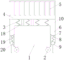
FIG. 1 is a schematic structural view of the present invention;
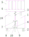
FIG. 2 is an enlarged sectional view of the internal structure of the container body according to the present invention;
FIG. 3 is a right view of the structure of the present invention.
In the figure: 1. a box body; 2. a moving wheel; 3. a first spring; 4. a fixing plate; 5. a guardrail; 6. mounting a plate; 7. a fixed block; 8. a second spring; 9. a grounding probe; 10. a ground line; 11. a third spring; 12. moving the plate; 13. a fourth spring; 14. a buffer plate; 15. a moving block; 16. a fifth spring; 17. a connecting plate; 18. a buffer column; 19. a first chute; 20. a first slider; 21. a limiting plate; 22. a second chute; 23. a second slider; 24. a third chute; 25. and a third slide block.
Detailed Description
The technical solutions in the embodiments of the present invention will be clearly and completely described below with reference to the drawings in the embodiments of the present invention, and it is obvious that the described embodiments are only a part of the embodiments of the present invention, and not all of the embodiments. All other embodiments, which can be derived by a person skilled in the art from the embodiments given herein without making any creative effort, shall fall within the protection scope of the present invention.
In the description herein, it is to be understood that the terms "center," "upper," "lower," "front," "rear," "left," "right," "vertical," "horizontal," "top," "bottom," "inner," "outer," and the like are used in the orientations and positional relationships indicated in the drawings to facilitate the description of the patent and to simplify the description, but do not indicate or imply that the referenced device or element must have a particular orientation, be constructed and operated in a particular orientation, and thus are not to be considered limiting of the patent. In the description of the present application, it should be noted that unless otherwise explicitly stated or limited, the terms "mounted," "connected," and "disposed" are to be construed broadly and can, for example, be fixedly connected, disposed, detachably connected, disposed, or integrally connected and disposed. The specific meaning of the above terms in this patent may be understood by those of ordinary skill in the art as appropriate.
Referring to fig. 1-3, an electric leakage prevention surveying device for electric power engineering design includes a box 1, moving wheels 2 fixedly connected to four corners of the bottom of the box 1, a first spring 3 fixedly connected to the top of the box 1, a fixed plate 4 fixedly connected to the top of the first spring 3, a guardrail 5 fixedly connected to the top of the fixed plate 4, mounting plates 6 fixedly mounted to the bottoms of two sides of the box 1, a fixed block 7 fixedly connected to the top of the outer side of the mounting plate 6, a second spring 8 fixedly connected to the bottom of the fixed block 7, a grounding probe 9 fixedly connected to the bottom of the second spring 8, a grounding wire 10 fixedly mounted to the outer side of the grounding probe 9, a third spring 11 fixedly connected to the bottom of the inner wall of the box 1, a moving plate 12 fixedly connected to the top of the third spring 11, and a fourth spring 13 fixedly connected to the top of the moving plate 12, the top of the fourth spring 13 is fixedly connected with a buffer plate 14, both sides of the buffer plate 14 are fixedly connected with moving blocks 15, both the top and the bottom of the moving block 15 are fixedly connected with fifth springs 16, the outer side of the fifth spring 16 is fixedly connected with a connecting plate 17, the outer side of the connecting plate 17 is fixedly connected with the inner wall of the box body 1, both the front side and the rear side of the top of the buffer plate 14 are fixedly connected with buffer posts 18, the top of the buffer posts 18 penetrates through the top of the box body 1 and is fixedly connected with the bottom of the fixed plate 4, the outer side of the mounting plate 6 is provided with a first chute 19, the inner cavity of the first chute 19 is slidably connected with a first slide block 20, the outer side of the first slide block 20 is fixedly connected with the inner side of the grounding probe 9, both sides of the bottom of the inner wall of the box body 1 are fixedly connected with limit plates 21, the inner side of the limit plates 21 is provided with a second chute 22, the inner cavity of the second chute 22 is slidably connected with a second slide block 23, the inner side of the second sliding block 23 is fixedly connected with the outer side of the moving plate 12, the tops of two sides of the inner wall of the box body 1 are respectively provided with a third sliding groove 24, the inner cavity of the third sliding groove 24 is connected with a third sliding block 25 in a sliding manner, the inner side of the third sliding block 25 is fixedly connected with the outer side of the moving block 15, the front side and the rear side of the top of the box body 1 are respectively provided with a through groove, the diameter of the through groove inner cavity is larger than that of the buffer column 18, the front side and the rear side of the top and the bottom of the mounting plate 6 are respectively and fixedly connected with a mounting block, the outer side of the mounting block is fixedly mounted with the surface of the box body 1 through bolts, the mounting plate 6, the fixing block 7, the second spring 8, the grounding probe 9, the grounding wire 10, the first sliding groove 19 and the first sliding block 20 are matched with each other, the device has the functions of grounding and conducting electricity, the leakage is avoided, and the third spring 11 has the functions of elastic buffering and shock absorption for the moving plate 12, the fourth spring 13 is arranged to play a role of elastic buffering and damping on the buffer plate 14, the fifth spring 16 is arranged to play a role of elastic buffering and damping on the moving block 15 and the buffer plate 14, the first sliding groove 19 and the first sliding block 20 are arranged to play a role of stabilizing the grounding probe 9 during moving, the limiting plate 21, the second sliding groove 22 and the second sliding block 23 are arranged to play a role of stabilizing the moving plate 12 during moving, the third sliding groove 24 and the third sliding block 25 are arranged to play a role of stabilizing the moving block 15 and the buffer plate 14 during moving, the mounting plate 6, the fixed block 7, the second spring 8, the grounding probe 9, the grounding wire 10, the first sliding groove 19 and the first sliding block 20 are arranged to be matched with each other to play a role of grounding conduction on the device, so that the situation of electric leakage is avoided, and the third spring 11, the moving plate 12, the fourth spring 13, the third sliding block 22, the second sliding block 20, the third sliding groove 22 and the second sliding block 25 are arranged to be matched with each other, Buffer board 14, moving block 15, fifth spring 16, connecting plate 17, buffering post 18, limiting plate 21, second spout 22, second slider 23, third spout 24 and third slider 25 mutually support, reached and to having avoided electric leakage to survey the advantage that device elasticity buffering shock attenuation performance is good, make and avoid electric leakage to survey the device when using, can effectually carry out elasticity buffering shock attenuation to avoiding electric leakage to survey the device, prevent to avoid electric leakage to survey the device and appear shock damage, prolonged the life who avoids electric leakage to survey the device, can satisfy user's user demand.
When the grounding probe is used, firstly, the grounding probe 9 is contacted with the ground, the grounding probe 9 is connected with the bottom of the fixed plate 4 through the grounding wire 10, meanwhile, when the grounding probe 9 is contacted with the ground, the grounding probe 9 moves to drive the first sliding block 20 to slide in the inner cavity of the first sliding groove 19, so that the grounding probe 9 moves stably, meanwhile, the grounding probe 9 moves to be extruded to the second spring 8, the grounding probe 9 is prevented from being damaged when being contacted with the ground, meanwhile, the fixed plate 4 and the guardrail 5 generate vibration when moving through the moving wheel 2, the fixed plate 4 vibrates to buffer and absorb shock through the elastic force of the first spring 3, meanwhile, the fixed plate 4 vibrates to drive the buffer column 18 to vibrate, the buffer column 18 vibrates to drive the buffer plate 14 to vibrate, the buffer plate 14 vibrates to drive the moving block 15 to vibrate, the moving block 15 vibrates to drive the third sliding block 25 to slide in the inner cavity of the third sliding groove 24, so that the moving block 15 moves stably, and meanwhile, the moving block 15 moves to buffer and absorb shock through the elastic force of the fifth spring 16, meanwhile, the buffer plate 14 vibrates to buffer and damp through the elastic force of the fourth spring 13, the moving plate 12 vibrates simultaneously, the moving plate 12 vibrates to drive the second sliding block 23 to slide in the inner cavity of the second sliding groove 22, the moving plate 12 moves stably, and meanwhile, the moving plate 12 vibrates to buffer and damp through the elastic force of the third spring 11, so that the fixed plate 4 is subjected to elastic force buffering and damping, and the advantage of good elastic force buffering and damping performance of the leakage-proof surveying device is achieved.
All the components in the utility model are universal standard components or components known by those skilled in the art, the structure and principle of the components can be known by technical manuals or conventional experimental methods, meanwhile, the standard components used in the application document can be purchased from the market, the components in the application document can be customized according to the description of the specification and the accompanying drawings, the specific connection mode of each component adopts the conventional means of mature bolts, rivets, welding and the like in the prior art, the machinery, the components and equipment adopt the conventional models in the prior art, the control mode is automatically controlled through a controller, the control circuit of the controller can be realized through simple programming of those skilled in the art, the components belong to the common knowledge in the art, and the application document is mainly used for protecting mechanical devices, so the detailed explanation of the control mode and circuit connection is omitted, no specific description is made here, and the peripheral controller mentioned in the specification may play a role of controlling the electric elements mentioned herein, and the peripheral controller is a conventionally known device.
Although embodiments of the present invention have been shown and described, it will be appreciated by those skilled in the art that changes, modifications, substitutions and alterations can be made in these embodiments without departing from the principles and spirit of the utility model, the scope of which is defined in the appended claims and their equivalents.
Claims (6)
1. Electric power engineering design is with avoiding electric leakage survey device, including box (1), its characterized in that: the all-four-corner fixedly connected moving wheel (2) at the bottom of the box body (1), a first spring (3) fixedly connected to the top of the box body (1), a fixed plate (4) fixedly connected to the top of the first spring (3), a guardrail (5) fixedly connected to the top of the fixed plate (4), mounting plates (6) fixedly mounted to the bottoms of the two sides of the box body (1), a fixed block (7) fixedly connected to the top of the outer side of the mounting plate (6), a second spring (8) fixedly connected to the bottom of the fixed block (7), a grounding probe (9) fixedly connected to the bottom of the second spring (8), a grounding wire (10) fixedly mounted to the outer side of the grounding probe (9), a third spring (11) fixedly connected to the top of the grounding wire (10) and the bottom of the fixed plate (4), and the bottom of the inner wall of the box body (1), the top of the third spring (11) is fixedly connected with a moving plate (12), the top of the moving plate (12) is fixedly connected with a fourth spring (13), the top of the fourth spring (13) is fixedly connected with a buffer plate (14), two sides of the buffer plate (14) are respectively and fixedly connected with a moving block (15), the top and the bottom of the moving block (15) are respectively and fixedly connected with a fifth spring (16), the outer side of the fifth spring (16) is fixedly connected with a connecting plate (17), the outer side of the connecting plate (17) is fixedly connected with the inner wall of the box body (1), the front side and the rear side of the top of the buffer plate (14) are respectively and fixedly connected with a buffer column (18), and the top of the buffer column (18) penetrates through to the top of the box body (1) and the bottom of the fixed plate (4).
2. An electrical leakage avoidance survey apparatus according to claim 1, wherein: first spout (19) have been seted up in the outside of mounting panel (6), the inner chamber sliding connection of first spout (19) has first slider (20), the inboard fixed connection of the outside of first slider (20) and ground connection probe (9).
3. An electrical leakage avoidance survey apparatus according to claim 1, wherein: the equal fixedly connected with limiting plate (21) in both sides of box (1) inner wall bottom, second spout (22) have been seted up to the inboard of limiting plate (21), the inner chamber sliding connection of second spout (22) has second slider (23), the inboard and movable plate (12) outside fixed connection of second slider (23).
4. An electrical leakage avoidance survey apparatus according to claim 1, wherein: third sliding grooves (24) are formed in the tops of two sides of the inner wall of the box body (1), third sliding blocks (25) are connected to the inner cavities of the third sliding grooves (24) in a sliding mode, and the inner sides of the third sliding blocks (25) are fixedly connected with the outer sides of the moving blocks (15).
5. An electrical leakage avoidance survey apparatus according to claim 1, wherein: the front side and the rear side of the top of the box body (1) are both provided with through grooves, and the diameter of the through groove inner cavity is larger than that of the buffer column (18).
6. An electrical leakage avoidance survey apparatus according to claim 1, wherein: the front side and the rear side of the top and the bottom of the mounting plate (6) are fixedly connected with mounting blocks, and the outer sides of the mounting blocks are fixedly mounted with the surface of the box body (1) through bolts.
Priority Applications (1)
| Application Number | Priority Date | Filing Date | Title |
|---|---|---|---|
| CN202122141893.XU CN215678489U (en) | 2021-09-06 | 2021-09-06 | Electric leakage prevention survey device for electric power engineering design |
Applications Claiming Priority (1)
| Application Number | Priority Date | Filing Date | Title |
|---|---|---|---|
| CN202122141893.XU CN215678489U (en) | 2021-09-06 | 2021-09-06 | Electric leakage prevention survey device for electric power engineering design |
Publications (1)
| Publication Number | Publication Date |
|---|---|
| CN215678489U true CN215678489U (en) | 2022-01-28 |
Family
ID=79960066
Family Applications (1)
| Application Number | Title | Priority Date | Filing Date |
|---|---|---|---|
| CN202122141893.XU Active CN215678489U (en) | 2021-09-06 | 2021-09-06 | Electric leakage prevention survey device for electric power engineering design |
Country Status (1)
| Country | Link |
|---|---|
| CN (1) | CN215678489U (en) |
-
2021
- 2021-09-06 CN CN202122141893.XU patent/CN215678489U/en active Active
Similar Documents
| Publication | Publication Date | Title |
|---|---|---|
| CN205960480U (en) | High shock resistance nuclear level medium voltage switchgear | |
| CN215678489U (en) | Electric leakage prevention survey device for electric power engineering design | |
| CN205985811U (en) | Electric power cabinet base with shock attenuation effect | |
| CN204290123U (en) | Novel three pillar type seal | |
| CN215645526U (en) | Anti-collision power control electric cabinet | |
| CN213484307U (en) | Novel outdoor power distribution cabinet | |
| CN206099251U (en) | Be used for knob insulator type electrical equipment absorbing hybrid control device | |
| CN214958168U (en) | A installation base for electrical control cabinet | |
| CN214044539U (en) | Box-type substation with loss prevention protect function | |
| CN211017837U (en) | High-voltage switch cabinet | |
| CN216530499U (en) | Cable connecting device for electric power construction | |
| CN210984457U (en) | Anti-seismic transformer | |
| CN213584713U (en) | High-voltage power distribution cabinet with shock-absorbing function | |
| CN210430611U (en) | Shockproof high-voltage switch cabinet | |
| CN210467499U (en) | Height-adjustable oil-immersed transformer | |
| CN215772147U (en) | High-efficient shock-resistant high-low voltage distribution cabinet | |
| CN113363834A (en) | Cubical switchboard safety protection mechanism and cubical switchboard | |
| CN217362286U (en) | High tension switchgear with subassembly takes precautions against earthquakes | |
| CN210246548U (en) | Mounting structure of generator regulator | |
| CN214706818U (en) | Energy-saving totally-enclosed high-low voltage switch cabinet | |
| CN206388635U (en) | A kind of high-pressure vacuum breaker with antivibration effect | |
| CN214044472U (en) | European style looped netowrk cabinet that anti-seismic performance is good | |
| CN214012739U (en) | Power equipment vibration isolation installation device | |
| CN220342672U (en) | Wind power generation high-voltage dynamic passive filtering compensation device | |
| CN214755003U (en) | Effectual cubical switchboard combats earthquake |
Legal Events
| Date | Code | Title | Description |
|---|---|---|---|
| GR01 | Patent grant | ||
| GR01 | Patent grant |