CN215654493U - Circulation self-cleaning formula high-pressure pulse dust remover - Google Patents
Circulation self-cleaning formula high-pressure pulse dust remover Download PDFInfo
- Publication number
- CN215654493U CN215654493U CN202122069534.8U CN202122069534U CN215654493U CN 215654493 U CN215654493 U CN 215654493U CN 202122069534 U CN202122069534 U CN 202122069534U CN 215654493 U CN215654493 U CN 215654493U
- Authority
- CN
- China
- Prior art keywords
- dust
- dust remover
- remover body
- dust collector
- pressure pulse
- Prior art date
- Legal status (The legal status is an assumption and is not a legal conclusion. Google has not performed a legal analysis and makes no representation as to the accuracy of the status listed.)
- Active
Links
Images


Abstract
The utility model discloses a circulating self-cleaning high-voltage pulse dust collector which comprises a dust collector body and a vibration mechanism, wherein one side of the dust collector body is connected with a protective guard, the protective guard and one side of the dust collector body are detachably connected, the bottom of the protective guard is connected with a crawling ladder, the bottom of the dust collector body is connected with a dust collection hopper, one side of the dust collection hopper is connected with the vibration mechanism, the bottom of the dust collection hopper is provided with a dust collection barrel, and one side of the dust collector body is connected with an air inlet pipe. According to the utility model, after dust is removed from materials, impurities such as dust are discharged and collected through the dust collecting hopper, after the motor is started through external control, the connecting rod and the knocking hammer can be driven to move under the action of meshing connection of the gear and the rack, so that the dust collecting hopper is contacted with one side of the dust collecting hopper to knock repeatedly, the dust can be further accelerated to be discharged quickly, and the problem of dust accumulated on the inner wall of the dust collecting hopper is avoided.
Description
Technical Field
The utility model relates to the technical field of industrial dust removal treatment in the photoelectric panel industry, in particular to a circulating self-cleaning high-voltage pulse dust remover.
Background
The photoelectric panel carries dust more or less in the production and processing processes, if the photoelectric panel is not processed in time, the later processing procedures can be influenced, the use of the photoelectric panel can be impressed, the existence of the dust and the dust can directly influence the health of workers, but the existing dust remover has low efficiency, is easy to cause material blockage in equipment, and can directly and seriously influence the service life of the equipment; moreover, the working efficiency of dust collection is low, and the dust cannot be prevented from being accumulated in the equipment due to improper dust collection.
SUMMERY OF THE UTILITY MODEL
The utility model aims to provide a circulating self-cleaning high-voltage pulse dust collector, which aims to solve the problems that the existing dust collector in the background art has low efficiency, is easy to cause material blockage in equipment, can directly and seriously influence the service life of the equipment and the like.
In order to achieve the purpose, the utility model provides the following technical scheme: the utility model provides a circulation is from clearance formula high-voltage pulse dust remover, includes dust remover body, vibration mechanism, antiskid ribbed tile and circulation roller, one side of dust remover body is connected and is provided with the rail guard, the rail guard belongs to dismantle with dust remover body one side and is connected the setting, and the bottom of rail guard is connected and is provided with the cat ladder to the bottom of dust remover body is connected and is provided with the ash collecting hopper, one side of ash collecting hopper is connected and is provided with vibration mechanism, and the bottom installation of ash collecting hopper is provided with a dust collection section of thick bamboo, and one side connection of dust remover body is provided with the air-supply line, the bottom installation of air-supply line is provided with the air-supply line, and the air-supply line belongs to fixed connection with the dust remover body and sets up.
Preferably, one side of the dust remover body is connected with an opening and closing door, the back position of the dust remover body is connected with an air outlet pipe, and the bottom of the air outlet pipe is provided with an air outlet machine.
Preferably, the dust remover body is internally provided with an electrostatic ash removal half-ring plate in a connected manner, a circulating roller is arranged in the electrostatic ash removal half-ring plate in an internally connected manner, and a blowing type powder removal and impurity removal half-ring plate is arranged below the electrostatic ash removal half-ring plate.
Preferably, the bottom connection of dust remover body inside is provided with the screening and filters the otter board, and the below of screening and filtering the otter board and the bottom connection of dust remover body are provided with the opening to the inside pipeline spread groove that is provided with in one side of dust remover body, the top connection of dust remover body is provided with the feed inlet.
Preferably, a connecting rod is arranged in the vibration mechanism, and one end of the connecting rod and one side of the dust collecting hopper are connected and provided with a knocking hammer.
Preferably, the bottom of the connecting rod is connected with a toothed bar, the bottom of the toothed bar is provided with a gear, and the back position of the gear is connected with a motor.
Preferably, the bottom of gear is connected and is provided with and places the board, and the bottom of dust remover body both sides all is connected and is provided with the support frame.
Preferably, the bottom of the dust collecting barrel is connected with an underframe, and the bottom of the underframe is provided with a plurality of rows of wheels.
Preferably, the tops of the two ends of the bottom frame are provided with electric telescopic rods in a connected mode, and the bottoms of the electric telescopic rods and the bottoms of the two ends of the bottom frame are provided with anti-skid plates in a connected mode.
Compared with the prior art, the utility model has the beneficial effects that:
(1) according to the circulating self-cleaning high-voltage pulse dust collector, after dust is removed from materials through the dust collecting hopper, the connecting rod, the knocking hammer, the rack rod, the gear, the motor, the placing plate, the supporting frame and other accessories, impurities such as dust are discharged and collected through the dust collecting hopper, after the motor is started through external control, the connecting rod and the knocking hammer can be driven to move under the action of meshing connection of the gear and the rack rod, one side of the dust collecting hopper is contacted and repeatedly knocked, the dust can be further accelerated to be rapidly discharged, and the problem of being accumulated on the inner wall of the dust collecting hopper is avoided;
(2) according to the circulating self-cleaning high-voltage pulse dust collector, the accessories such as the electrostatic ash removal half-ring plate, the circulating roller, the blowing type powder and impurity removal half-ring plate, the pipeline connecting groove and the like are arranged, one end of the pipeline connecting groove is convenient to communicate with the interior of the dust collector body, after wind power is blown into the interior of the dust collector body, the circulating roller rotates along with the wind power, materials placed in the electrostatic ash removal half-ring plate can be pushed to rotate, so that dust is better adsorbed by static electricity generated in the electrostatic ash removal half-ring plate, dust contained in the materials in the blowing type powder and impurity removal half-ring plate can be smoothly blown off by the rotation of the circulating roller by hand, the efficiency of removing dust and impurities in the equipment can be effectively improved, and the energy saving and low consumption performance is embodied;
(3) this kind of circulation is from clearance formula high-voltage pulse dust remover, through at the air-supply line, go out the tuber pipe, go out accessories such as fan and screening filter screen board, the cooperation of air-supply line and air-supply line realizes that wind-force can blow into the dust remover body inside and carry out the dust removal effect, and utilize the cooperation wind-force of going out tuber pipe and fan to carry the dust and wait for by the work of collecting, then the air carries the dust and filters through screening filter screen board, the work of using repeatedly of back so that next wind-force after the last air is collected embodies the performance of environmental protection.
Drawings
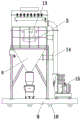
FIG. 1 is a schematic front view of the present invention;
FIG. 2 is an enlarged view of the structure at A in FIG. 1 according to the present invention;
FIG. 3 is a schematic side view of the present invention;
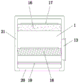
FIG. 4 is a schematic view of the internal structure of the main body of the dust catcher of the present invention;
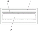
FIG. 5 is a schematic top view of the electrostatic precipitator half-ring plate according to the present invention.
In the figure: 1. a dust collector body; 2. protecting the fence; 3. climbing a ladder; 4. a dust collecting hopper; 5. a vibration mechanism; 501. a connecting rod; 502. knocking the hammer; 503. a rack bar; 504. a gear; 505. a motor; 506. placing the plate; 507. a support frame; 6. a dust collecting cylinder; 7. an air inlet pipe; 8. an air inlet machine; 9. a chassis; 10. a row wheel; 11. an electric telescopic rod; 12. an anti-skid plate; 13. opening and closing the door; 14. an air outlet pipe; 15. an air outlet machine; 16. electrostatic ash removal half-ring plate; 17. a circulating roller; 18. air-blowing type powder and impurity removal half-circle plate; 19. screening a filter screen plate; 20. a port; 21. connecting grooves of pipelines; 22. and (4) feeding a material inlet.
Detailed Description
The technical solutions in the embodiments of the present invention will be clearly and completely described below with reference to the drawings in the embodiments of the present invention, and all other embodiments obtained by a person of ordinary skill in the art based on the embodiments of the present invention without any creative efforts belong to the protection scope of the present invention.
Referring to fig. 1-5, an embodiment of the present invention is shown: a circulating self-cleaning high-voltage pulse dust collector, which comprises a dust collector body 1, a vibration mechanism 5, an antiskid plate 12 and a circulating roller 17, a protective guard 2 is connected and arranged on one side of the dust remover body 1, the protective guard 2 and one side of the dust remover body 1 are detachably connected and arranged, a ladder stand 3 is connected and arranged at the bottom of the protective guard 2, and the bottom of the dust collector body 1 is connected with a dust collecting hopper 4, one side of the dust collecting hopper 4 is connected with a vibration mechanism 5, a connecting rod 501 is arranged inside the vibration mechanism 5, the bottom of the connecting rod 501 is connected with a toothed bar 503, the bottom of the toothed bar 503 is provided with a gear 504, a motor 505 is connected to the back of the gear 504, the guard rail 2 and the ladder stand 3 are arranged to facilitate checking and repairing of equipment conditions by workers, and the knocking hammer 502 can perform repeated knocking operation on one side of the dust hopper 4 by matching the toothed bar 503 and the gear 504;
one end of the connecting rod 501 and one side of the dust collecting hopper 4 are connected with a rapping hammer 502, the connecting rod 501 is fixedly connected with the rapping hammer 502, and the left-right movement can be realized through the action of a toothed bar 503 and a gear 504;
the bottom installation of dust hopper 4 is provided with dust collection tube 6 to one side of dust remover body 1 is connected and is provided with air-supply line 7, the bottom installation of air-supply line 7 is provided with air-supply line 8, and air-supply line 7 and dust remover body 1 belong to fixed connection and set up, and air-supply line 7 realizes carrying out the formula of blowing dust removal work to dust remover body 1 inside through the effect of air-supply line 8, and is efficient and low noise environmental protection.
One side of dust remover body 1 is connected and is provided with switching door 13, and the back position of dust remover body 1 connects and is provided with out tuber pipe 14 to the bottom installation of going out tuber pipe 14 is provided with out fan 15, and the control that goes out tuber pipe 14 through out fan 15 realizes collecting the inside air of dust remover body 1, and the air at the back of being convenient for is used repeatedly.
The connection of the inside top of dust remover body 1 is provided with electrostatic precipitator half circle board 16, and the internal connection of electrostatic precipitator half circle board 16 is provided with circulation roller 17, and the below of electrostatic precipitator half circle board 16 is provided with formula of blowing dust removal edulcoration half circle board 18, circulation roller 17 and the inside both ends department swing joint of electrostatic precipitator half circle board 16, it can carry out pivoted work to make wind blow, electrostatic precipitator half circle board 16 has electrostatic adsorption, be convenient for adsorb the dust that the material kind carried, formula of blowing dust removal edulcoration half circle board 18 can supply to bear wind-force, the dust of being convenient for wind-force to carry in with inside material is clear away.
The inside bottom of dust remover body 1 is connected and is provided with screening filter screen board 19, and the below of screening filter screen board 19 and the bottom connection of dust remover body 1 are provided with opening 20 to the inside pipeline spread groove 21 that is provided with in one side of dust remover body 1, the top connection of dust remover body 1 is provided with feed inlet 22, and screening filter screen board 19 is to screening through the material of here, and then unqualified material can sort out alone, and later stage accessible switching door 13 takes out, also can filter the air of siphoning away, waits for the secondary use.
The bottom of the gear 504 is connected with a placing plate 506, the bottoms of the two sides of the dust collector body 1 are connected with supporting frames 507, the supporting frames 507 support the whole device, and the placing plate 506 supports the motor 505.
The bottom of the dust collecting cylinder 6 is connected with an underframe 9, and the bottom of the underframe 9 is provided with a plurality of row wheels 10. The provision of the row wheel 10 facilitates the work of stably moving the entire apparatus.
The both ends top of chassis 9 is all connected and is provided with electric telescopic handle 11, and the bottom at electric telescopic handle 11 and the bottom at chassis 9 both ends are connected and are provided with antiskid ribbed tile 12, and electric telescopic handle 11 can drive antiskid ribbed tile 12 and go up and down, then antiskid ribbed tile 12 and ground contact then realize increasing the frictional property of equipment bottom, avoid appearing the phenomenon of displacement.
The working principle is as follows: when in use, materials needing dust removal are put into the dust remover body 1 through the feeding hole 22, the air inlet machine 8 and the air outlet machine 15 are started, the circulating roller 17 is driven to rotate by wind power generated by absorbing air, the circulating roller 17 is rotated to stir the materials in the electrostatic dust removal semi-ring plate 16, when the materials are separated from dust, the materials are adsorbed by the static electricity carried by the electrostatic dust removal semi-ring plate 16, the wind power also drives the circulating roller 17 arranged in the blowing type dust removal and impurity removal semi-ring plate 18 to rotate, the dust in the materials in the blowing type dust removal and impurity removal semi-ring plate 18 is blown by the wind power, redundant dust impurities are filtered by the screening and filtering screen plate 19, the screening and filtering screen plate 19 can also screen unqualified products in the materials, and finally, the dust impurities are collected through the opening door 13, the dust impurities after dust removal can pass through the dust collecting hopper 4 and can be absorbed through the opening 20, the knocking hammer 502 is driven by the motor 505 and the gear 504 to move, so that the dust hopper 4 can be knocked regularly and repeatedly, and the dust discharging speed is increased.
Claims (9)
1. A circulating self-cleaning high-voltage pulse dust collector is characterized by comprising a dust collector body (1), a vibration mechanism (5), an antiskid plate (12) and a circulating roller (17), one side of the dust remover body (1) is connected with a protective guard (2), the protective guard (2) and one side of the dust remover body (1) are detachably connected, the bottom of the protective guard (2) is connected with a ladder stand (3), and the bottom of the dust remover body (1) is connected with a dust collecting hopper (4), one side of the dust collecting hopper (4) is connected with a vibration mechanism (5), the bottom of the dust collecting hopper (4) is provided with a dust collecting cylinder (6), an air inlet pipe (7) is connected and arranged at one side of the dust remover body (1), an air inlet machine (8) is arranged at the bottom of the air inlet pipe (7), and the air inlet pipe (7) and the dust remover body (1) are fixedly connected.
2. A cyclic self-cleaning high-pressure pulse dust collector as claimed in claim 1, wherein: one side of the dust remover body (1) is connected with an opening and closing door (13), the back position of the dust remover body (1) is connected with an air outlet pipe (14), and the bottom of the air outlet pipe (14) is provided with an air outlet machine (15).
3. A cyclic self-cleaning high-pressure pulse dust collector as claimed in claim 2, wherein: the dust remover comprises a dust remover body (1), wherein an electrostatic ash removal half-ring plate (16) is connected to the upper part of the interior of the dust remover body (1), a circulating roller (17) is connected to the interior of the electrostatic ash removal half-ring plate (16), and a blowing type powder removal and impurity removal half-ring plate (18) is arranged below the electrostatic ash removal half-ring plate (16).
4. A cyclic self-cleaning high-pressure pulse dust collector as claimed in claim 3, wherein: the bottom connection of dust remover body (1) inside is provided with screening filter screen board (19), and the below of screening filter screen board (19) and the bottom connection of dust remover body (1) are provided with opening (20) to the inside pipeline spread groove (21) that is provided with in one side of dust remover body (1), the top connection of dust remover body (1) is provided with feed inlet (22).
5. A cyclic self-cleaning high-pressure pulse dust collector as claimed in claim 1, wherein: a connecting rod (501) is arranged in the vibration mechanism (5), and one end of the connecting rod (501) and one side of the dust collecting hopper (4) are connected with a knocking hammer (502).
6. The circulating self-cleaning high-pressure pulse dust collector as claimed in claim 5, wherein: the bottom of the connecting rod (501) is provided with a toothed bar (503) in a connecting manner, the bottom of the toothed bar (503) is provided with a gear (504), and the back position of the gear (504) is provided with a motor (505) in a connecting manner.
7. The circulating self-cleaning high-pressure pulse dust collector as claimed in claim 6, wherein: the bottom of the gear (504) is connected with a placing plate (506), and the bottoms of the two sides of the dust remover body (1) are both connected with a supporting frame (507).
8. A cyclic self-cleaning high-pressure pulse dust collector as claimed in claim 1, wherein: the bottom of the dust collection cylinder (6) is connected with an underframe (9), and the bottom of the underframe (9) is provided with a plurality of rows of wheels (10).
9. A cyclic self-cleaning high-pressure pulse precipitator in accordance with claim 8, wherein: the top parts of the two ends of the bottom frame (9) are all connected with electric telescopic rods (11), and the bottoms of the electric telescopic rods (11) and the bottoms of the two ends of the bottom frame (9) are connected with anti-skid plates (12).
Priority Applications (1)
| Application Number | Priority Date | Filing Date | Title |
|---|---|---|---|
| CN202122069534.8U CN215654493U (en) | 2021-08-30 | 2021-08-30 | Circulation self-cleaning formula high-pressure pulse dust remover |
Applications Claiming Priority (1)
| Application Number | Priority Date | Filing Date | Title |
|---|---|---|---|
| CN202122069534.8U CN215654493U (en) | 2021-08-30 | 2021-08-30 | Circulation self-cleaning formula high-pressure pulse dust remover |
Publications (1)
| Publication Number | Publication Date |
|---|---|
| CN215654493U true CN215654493U (en) | 2022-01-28 |
Family
ID=79957461
Family Applications (1)
| Application Number | Title | Priority Date | Filing Date |
|---|---|---|---|
| CN202122069534.8U Active CN215654493U (en) | 2021-08-30 | 2021-08-30 | Circulation self-cleaning formula high-pressure pulse dust remover |
Country Status (1)
| Country | Link |
|---|---|
| CN (1) | CN215654493U (en) |
-
2021
- 2021-08-30 CN CN202122069534.8U patent/CN215654493U/en active Active
Similar Documents
| Publication | Publication Date | Title |
|---|---|---|
| CN206296074U (en) | A kind of electrostatic precipitator | |
| CN211025656U (en) | Anhydrous raise dust processing apparatus for building engineering | |
| CN215654493U (en) | Circulation self-cleaning formula high-pressure pulse dust remover | |
| CN113798061A (en) | Quick deashing structure of electrostatic precipitator | |
| CN213273104U (en) | Air freshener convenient for descaling | |
| CN216395757U (en) | Multifunctional module formula dust remover | |
| CN216498117U (en) | A dust collector for cotton yarn production and processing | |
| CN215585756U (en) | Blast furnace feeding bag-type dust collector | |
| CN214680922U (en) | Zeolite runner adsorption concentration device | |
| CN215138272U (en) | Waste gas treatment device with automatic cleaning function for coating machine | |
| CN210729851U (en) | Integrated waste gas purification equipment based on high-voltage static electricity | |
| CN219647005U (en) | High-efficiency gas dust remover | |
| CN220589341U (en) | Dust removing device of cutting equipment | |
| CN217615301U (en) | Environment-friendly electromagnetic pulse dust remover | |
| CN219129555U (en) | Environment-friendly dust remover for dust recovery and purification | |
| CN216936495U (en) | Micro-channel electric dust remover | |
| CN212103417U (en) | Grey cloth sweeping device | |
| CN220300945U (en) | Doffing device convenient for doffing | |
| CN210410033U (en) | Dust collector of heating furnace for forging | |
| CN219209336U (en) | High-efficient dust collector | |
| CN219559012U (en) | Industrial automation produces dust collecting equipment | |
| CN220176350U (en) | Continuous dust removal device | |
| CN217614995U (en) | Civil engineering is with waste material processing apparatus who has dust fall structure | |
| CN220361654U (en) | Steel shot dust collecting equipment convenient to dismouting | |
| CN216825371U (en) | Efficient integrated configuration dust remover |
Legal Events
| Date | Code | Title | Description |
|---|---|---|---|
| GR01 | Patent grant | ||
| GR01 | Patent grant |