CN215653014U - Needleless connecting piece - Google Patents
Needleless connecting piece Download PDFInfo
- Publication number
- CN215653014U CN215653014U CN202022784591.XU CN202022784591U CN215653014U CN 215653014 U CN215653014 U CN 215653014U CN 202022784591 U CN202022784591 U CN 202022784591U CN 215653014 U CN215653014 U CN 215653014U
- Authority
- CN
- China
- Prior art keywords
- base
- luer connector
- upper cover
- compression sealing
- connector
- Prior art date
- Legal status (The legal status is an assumption and is not a legal conclusion. Google has not performed a legal analysis and makes no representation as to the accuracy of the status listed.)
- Active
Links
Images


Landscapes
- Infusion, Injection, And Reservoir Apparatuses (AREA)
Abstract
The utility model relates to the field of medical instruments, in particular to a needleless connecting piece. Comprises an upper cover and a base; the upper cover is fixedly arranged on the base, an internal cavity formed by the upper cover and the base is communicated up and down, and an elastic compression sealing piece is arranged in the cavity; a female luer connector is arranged at the upper end of the upper cover, and an upper cover protective sleeve is screwed on the female luer connector; the bottom end of the base is provided with a male luer connector, and a bottom end protective cover is screwed on the male luer connector. The utility model generates positive pressure after pulling the needle, effectively prevents blood from flowing back and clotting blood and avoids the blockage of an indwelling tube. A special silica gel elastic closed structure is adopted, so that a liquid path in the catheter is always in a closed state, and catheter-related blood stream infection (CRBSI) is effectively prevented. The universal luer connector of international standard is adopted, and can be well matched with an injector and an infusion apparatus, the spiral connection is tight, and the liquid is ensured not to leak. Ensuring that the container is not contaminated after being unsealed.
Description
Technical Field
The utility model relates to the field of medical instruments, in particular to a needleless connecting piece.
Background
With the rapid development of intravenous infusion, a needle-free closed infusion technology is also widely applied to clinic, needle-free infusion refers to a device which can repeatedly convey or extract liquid to an infusion pipeline without puncture, and a needle-free infusion joint is adopted to provide a flow channel and an injection port for infusion.
Most of the conventional needleless infusion connectors are complex in structure, complex in operation and poor in airtightness, and cannot eliminate liquid return, liquid blockage and residual liquid medicine in the connectors, so that the probability of infection of patients in the infusion process is brought. The interfaces at the two ends of the existing needleless infusion joint have no protection measures and can be polluted before use.
Disclosure of Invention
The utility model aims to overcome the defects in the prior art and provides a needleless connector.
The technical scheme for realizing the purpose of the utility model is as follows: a needleless connector comprises an upper cover and a base; the upper cover is fixedly arranged on the base, an internal cavity formed by the upper cover and the base is communicated up and down, and an elastic compression sealing piece is arranged in the cavity; a female luer connector is arranged at the upper end of the upper cover, and an upper cover protective sleeve is screwed on the female luer connector; the liquid guide hole is formed in the top end of the base, the male luer connector is arranged at the bottom end of the base, and the bottom end protective cover is connected to the male luer connector in a rotating mode.
Furthermore, an installation ring groove is formed in the inner ring at the bottom of the upper cover, and the installation ring groove is fastened and clamped on the outer edge of the upper end of the base.
Furthermore, be equipped with the round back-off in the installation annular, the base is equipped with the round arch in the back-off corresponding position.
Furthermore, the upper end of the elastic compression sealing element is in a shape of a truncated cone with a large diameter and a small diameter, the upper end of the elastic compression sealing element is flush with the top end of the female luer connector and is in tight elastic contact with the inner ring of the female luer connector, the top end of the elastic compression sealing element is sealed, the bottom end of the elastic compression sealing element is communicated with the male luer connector, the base is provided with a conical hollow bulge protruding into the inner cavity, and the elastic compression sealing element is clamped on the conical hollow bulge.
Furthermore, the base is provided with a conical protrusion towards the inner cavity, the center of the top end of the conical protrusion is provided with a liquid guide hole, the conical protrusion jacks the upper end of the elastic compression sealing element to be in close elastic contact with the inner ring of the female luer connector, the top end of the elastic compression sealing element is flush with the top end of the female luer connector, and the center of the top end of the elastic compression sealing element is provided with a compression hole.
Further, the lower part of the elastic compression sealing element is in a corrugated bellows shape.
Furthermore, the outside of the bottom end protective cover is provided with a reinforcing rib, and two sides of the top end are outwards provided with fixing lugs screwed with the threads on the inner side of the male luer connector.
Furthermore, the elastic compression sealing element is made of silica gel.
After the technical scheme is adopted, the utility model has the following positive effects:
(1) the utility model generates positive pressure after pulling the needle, effectively prevents blood from flowing back and clotting blood and avoids the blockage of an indwelling tube.
(2) The utility model adopts a special silica gel elastic closed structure, ensures that the catheter is always in a closed state, and effectively prevents catheter-related blood stream infection (CRBSI).
(3) The utility model adopts the universal luer connector of international standard, can be well matched with an injector and an infusion apparatus, is tightly connected in a spiral way, and ensures that liquid does not leak.
(4) The utility model protects the medical care personnel to the limit, avoids the medical care personnel from being carelessly punctured and accidentally infected when the medical care personnel operates with a needle; the operation is simple and easy, and the disinfection is convenient, need not heparin tube sealing, alleviates clinical care personnel's work load.
(5) The utility model ensures that the seal is not contaminated after being unsealed.
Drawings
In order that the present disclosure may be more readily and clearly understood, reference is now made to the following detailed description of the present disclosure taken in conjunction with the accompanying drawings, in which
FIG. 1 is a schematic structural view of example 1;
FIG. 2 is a schematic structural view of example 2;
FIG. 3 is a schematic structural view of embodiment 3;
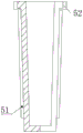
FIG. 4 is a cross-sectional view of the bottom protective cover.
Detailed Description
(example 1)
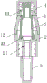
Referring to fig. 1 and 4, the present invention has an upper cover 1 and a base 2; the upper cover 1 is fixedly arranged on the base 2, an internal cavity formed by the upper cover 1 and the base 2 is communicated up and down, and an elastic compression sealing element 3 is arranged in the cavity; the elastic compression sealing element 3 is made of silica gel. A female luer connector 11 is arranged at the upper end of the upper cover 1, and an upper cover protective sleeve 4 is screwed on the female luer connector 11; the bottom end of the base 2 is provided with a male luer connector 21, and a bottom end protective cover 5 is screwed on the male luer connector 21. An installation ring groove 12 is formed in the inner ring of the bottom of the upper cover 1, and the installation ring groove 12 is fastened and clamped on the outer edge of the upper end of the base 2. The upper end of the elastic compression sealing element 3 is in a shape of a big end up and a small end down in diameter, the upper end of the elastic compression sealing element is flush with the top end of the female luer connector 11 and is in tight elastic contact with the inner ring of the female luer connector 11, the top end of the elastic compression sealing element 3 is sealed, the bottom end of the elastic compression sealing element is communicated with the male luer connector 21, the base 2 is provided with a conical hollow bulge 23 protruding into the inner cavity, and the elastic compression sealing element 3 is clamped on the conical hollow bulge 23. The bottom end protective cover 5 is externally provided with a reinforcing rib 51, and two sides of the top end are outwards provided with fixing lugs 52 screwed with the inner side threads of the male luer connector 21.
(example 2)
Referring to fig. 2, this embodiment is substantially the same as embodiment 1, and its distinctive features are: the base 2 is equipped with conical projection 24 to inside cavity, conical projection 24 top central point puts and is equipped with drain hole 25, conical projection 24 is with elasticity compression sealing member 3 upper end jack-up and female luer 11 inner circle closely elastic contact, and elasticity compression sealing member 3 top flushes with female luer 11 top, elasticity compression sealing member 3 top central point puts and is equipped with compression hole 31. The liquid guide hole 25 is communicated with a taper hole of a male luer connector of an infusion or injection device connected with a female luer connector to form a liquid path channel.
(example 3)
Referring to fig. 3, this embodiment is substantially the same as embodiment 2, and its difference features are: a circle of inverted buckles 13 are arranged in the mounting ring groove 12, and a circle of protrusions 22 are arranged on the base 2 at positions corresponding to the inverted buckles 13. The lower part of the elastic compression sealing element 3 is in a corrugated bellows shape.
The working principle of the utility model is as follows: the positive pressure is generated after the needle is pulled out, so that the blood backflow and the blood coagulation are effectively prevented, and the blockage of an indwelling tube is avoided. The special elastic silica gel sealing structure, namely the elastic compression sealing element 3, ensures that the catheter is always in a closed state, and effectively prevents related blood stream infection (CRBSI) of the catheter. The universal luer connector of international standard is adopted, and can be well matched with an injector and an infusion apparatus, the spiral connection is tight, and the liquid is ensured not to leak. Protecting medical care personnel and avoiding the medical care personnel from being accidentally punctured and infected when the medical care personnel operate with a needle; the operation is simple and easy, and the disinfection is convenient, need not heparin tube sealing, alleviates clinical care personnel's work load. The luer connectors at the two ends are ensured not to be polluted after being unsealed.
The above-mentioned embodiments are intended to illustrate the objects, technical solutions and advantages of the present invention in further detail, and it should be understood that the above-mentioned embodiments are only exemplary embodiments of the present invention, and are not intended to limit the present invention, and any modifications, equivalents, improvements and the like made within the spirit and principle of the present invention should be included in the protection scope of the present invention.
Claims (8)
1. A needleless connector, comprising: comprises an upper cover (1) and a base (2); the upper cover (1) is fixedly arranged on the base (2), an internal cavity formed by the upper cover (1) and the base (2) is communicated up and down, and an elastic compression sealing piece (3) is arranged in the cavity; a female luer connector (11) is arranged at the upper end of the upper cover (1), and an upper cover protective sleeve (4) is screwed on the female luer connector (11); the bottom end of the base (2) is provided with a male luer connector (21), and a bottom end protective cover (5) is screwed on the male luer connector (21).
2. The needleless connector of claim 1, wherein: the inner ring of the bottom of the upper cover (1) is provided with an installation ring groove (12), and the installation ring groove (12) is fastened and clamped on the outer edge of the upper end of the base (2).
3. The needleless connector of claim 2, wherein: be equipped with round back-off (13) in installation annular (12), base (2) are equipped with round arch (22) in back-off (13) corresponding position.
4. The needleless connector of claim 2, wherein: the upper end of the elastic compression sealing element (3) is in a shape of a big end up and a small end down in diameter and is flush with the top end of the female luer connector (11) and is in tight elastic contact with the inner ring of the female luer connector (11), the top end of the elastic compression sealing element (3) is sealed, the bottom end of the elastic compression sealing element is communicated with the male luer connector (21), the base (2) is provided with a conical hollow protrusion (23) protruding into the inner cavity, and the elastic compression sealing element (3) is clamped on the conical hollow protrusion (23).
5. The needleless connector of claim 2, wherein: base (2) are equipped with toper arch (24) to inside cavity, toper arch (24) top central point puts and is equipped with drain hole (25), toper arch (24) are with elasticity compression sealing member (3) upper end jack-up and female luer joint (11) inner circle in close elastic contact, and elasticity compression sealing member (3) top flushes with female luer joint (11) top, elasticity compression sealing member (3) top central point puts and is equipped with compression hole (31).
6. The needleless connector of claim 5, wherein: the lower part of the elastic compression sealing element (3) is in a corrugated bellows shape.
7. The needleless connector of claim 1, wherein: and reinforcing ribs (51) are arranged outside the bottom end protective cover (5), and fixing lugs (52) screwed with the threads on the inner side of the male luer connector (21) are arranged outwards on two sides of the top end.
8. The needleless connector of claim 1, wherein: the elastic compression sealing element (3) is made of silica gel.
Priority Applications (1)
| Application Number | Priority Date | Filing Date | Title |
|---|---|---|---|
| CN202022784591.XU CN215653014U (en) | 2020-11-27 | 2020-11-27 | Needleless connecting piece |
Applications Claiming Priority (1)
| Application Number | Priority Date | Filing Date | Title |
|---|---|---|---|
| CN202022784591.XU CN215653014U (en) | 2020-11-27 | 2020-11-27 | Needleless connecting piece |
Publications (1)
| Publication Number | Publication Date |
|---|---|
| CN215653014U true CN215653014U (en) | 2022-01-28 |
Family
ID=79949217
Family Applications (1)
| Application Number | Title | Priority Date | Filing Date |
|---|---|---|---|
| CN202022784591.XU Active CN215653014U (en) | 2020-11-27 | 2020-11-27 | Needleless connecting piece |
Country Status (1)
| Country | Link |
|---|---|
| CN (1) | CN215653014U (en) |
-
2020
- 2020-11-27 CN CN202022784591.XU patent/CN215653014U/en active Active
Similar Documents
| Publication | Publication Date | Title |
|---|---|---|
| CN218572631U (en) | Tearable anti-reflux catheter sheath with extension tube | |
| CN215653014U (en) | Needleless connecting piece | |
| CN109010990A (en) | A kind of novel infusion needleless joint | |
| CN211383152U (en) | Butterfly type anti-reflux needle-free quick connection indwelling needle | |
| CN208694038U (en) | A kind of connector | |
| CN209679264U (en) | A kind of three chamber urinary catheters with connector for bladder douching | |
| CN217854146U (en) | Three-cavity catheter without needle joint | |
| CN215386306U (en) | Urethral catheterization device convenient to change urine bag | |
| CN209092389U (en) | Remaining needle | |
| CN219423544U (en) | Anti-backflow infusion connecting pipe | |
| CN216855415U (en) | Draw and push integration intravenous route ware subassembly | |
| CN213526830U (en) | A add medicine subassembly for keeping somewhere needle | |
| CN214633180U (en) | Portable catheter | |
| CN209630327U (en) | A kind of needleless closed transfusion connector | |
| CN219941394U (en) | Extension type connecting pipe device | |
| CN220276126U (en) | Joint assembly for connecting catheter and injector | |
| CN213466317U (en) | Environment-friendly cross infection prevention disposable infusion apparatus | |
| CN215351218U (en) | Y-shaped positive-pressure needle-free infusion joint | |
| CN220193708U (en) | Double-cavity catheter is with dashing seal pipe syringe | |
| CN219375872U (en) | Anti-leakage positive pressure silica gel valve | |
| CN214859984U (en) | Remaining needle with good sealing effect and convenient insertion of isolating plug | |
| CN212395527U (en) | Special disposable indwelling needle infusion tube | |
| CN213941826U (en) | Three-cavity urinary catheter with flushing joint | |
| AU2013392518B2 (en) | Multifunctional indwelling needle | |
| CN216755124U (en) | Heparin cap with spiral positive pressure connector |
Legal Events
| Date | Code | Title | Description |
|---|---|---|---|
| GR01 | Patent grant | ||
| GR01 | Patent grant |