CN215649720U - Electric control extension table - Google Patents
Electric control extension table Download PDFInfo
- Publication number
- CN215649720U CN215649720U CN202121102644.3U CN202121102644U CN215649720U CN 215649720 U CN215649720 U CN 215649720U CN 202121102644 U CN202121102644 U CN 202121102644U CN 215649720 U CN215649720 U CN 215649720U
- Authority
- CN
- China
- Prior art keywords
- fixed
- movable plate
- screw
- fly leaf
- screw rod
- Prior art date
- Legal status (The legal status is an assumption and is not a legal conclusion. Google has not performed a legal analysis and makes no representation as to the accuracy of the status listed.)
- Active
Links
Images
Landscapes
- Transmission Devices (AREA)
Abstract
The utility model discloses an electric control extension table which comprises a first movable plate, a second movable plate and a third movable plate, wherein vertical plates are arranged at the bottoms of the first movable plate and the second movable plate in a sliding mode, a bottom plate is fixed between the bottoms of the two vertical plates, pulleys are fixed at the bottoms of the vertical plates, a driving mechanism for synchronously driving the first movable plate, the second movable plate and the third movable plate is arranged between the two vertical plates, the driving mechanism comprises a motor, the electric control extension table drives the first movable plate and the second movable plate to move towards the same direction or the opposite direction through the driving mechanism, and simultaneously drives the third movable plate to gradually rise until the third movable plate is positioned between the first movable plate and the second movable plate and positioned on the same horizontal line, so that the table top of the extension table is enlarged, and more people can participate in a conference conveniently.
Description
Technical Field
The utility model relates to the technical field of extension tables, in particular to an electric control extension table.
Background
The table is a common furniture, has a plane on the upper part and a pillar under the lower part, can be used for placing articles, doing things, eating, writing, working and the like on the table, is a furniture fixed by smooth flat plates, legs and other supports, can also be used as a noun in Chinese, is rich and various in types in order to meet the requirements of the public, and can be divided into various types according to the requirements, such as an office table, a dining table, a desk, a computer table, a teacher table and the like.
However, the existing office conference table is fixed in structure, does not have an extension function and has limitations.
SUMMERY OF THE UTILITY MODEL
The present invention is directed to an electrically controlled extendable table, which solves the above problems of the prior art.
In order to achieve the purpose, the utility model provides the following technical scheme: an electrically controlled extension table comprises a first movable plate, a second movable plate and a third movable plate, wherein vertical plates are arranged at the bottoms of the first movable plate and the second movable plate in a sliding mode, a bottom plate is fixed between the bottoms of the two vertical plates, pulleys are fixed at the bottoms of the vertical plates, and a driving mechanism for synchronously driving the first movable plate, the second movable plate and the third movable plate is arranged between the two vertical plates.
Further, actuating mechanism includes the motor, the motor is fixed on the bottom plate, is located and is fixed with horizontal conical gear on the motor shaft of motor output, horizontal conical gear meshing is connected with vertical conical gear, vertical conical gear fixes on the horizontal pole, be fixed with first gear on the horizontal pole, first gear meshing is connected in the second gear of fixing on first screw rod, the one end fixed connection of first screw rod is in the one end of second screw rod, the other end of first screw rod and second screw rod all is connected in the riser through first bearing.
Furthermore, first threaded sleeves are installed on the first screw rod and the second screw rod in a threaded mode, and the first threaded sleeves are fixedly connected to the bottoms of the first screw rod and the second screw rod through fixing seats.
Furthermore, a second threaded sleeve is fixed at the bottom of the third movable plate, the second threaded sleeve is installed on a third screw in a threaded mode, the bottom end of the third screw is connected to the bottom plate through a second bearing, fixing sleeves are fixed on the third screw and the motor shaft, and the two fixing sleeves are in transmission connection through a transmission belt.
Furthermore, a plurality of sleeve bearings are arranged on the cross rod and are fixed on the bottom plate through support rods.
Further, still be equipped with storage battery on the bottom plate, storage battery electric connection is in the motor, storage battery passes through charging wire and external power electric connection.
Furthermore, a through hole is formed in the third movable plate.
Compared with the prior art, the utility model has the beneficial effects that:
according to the electric control extension table, the first movable plate and the second movable plate are driven by the driving mechanism to move in the same or opposite directions, and the third movable plate is driven to gradually ascend until the third movable plate is located between the first movable plate and the second movable plate and located on the same horizontal line, so that the table top of the extension table is enlarged, and more people can participate in a conference conveniently.
Drawings
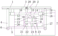
FIG. 1 is a schematic view of the present invention in an extended state;
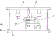
fig. 2 is a schematic view of the utility model in an unstretched state.
In the reference symbols: 1. a first movable plate; 2. a second movable plate; 3. a third movable plate; 4. a vertical plate; 5. a base plate; 6. a pulley; 7. a drive mechanism; 8. a motor; 9. a motor shaft; 10. a transverse bevel gear; 11. a vertical bevel gear; 12. a cross bar; 13. a first gear; 14. a first screw; 15. a second gear; 16. a second screw; 17. a first bearing; 18. a first threaded sleeve; 19. a fixed seat; 20. a second threaded sleeve; 21. a third screw; 22. a second bearing; 23. fixing the sleeve; 24. a transmission belt; 25. a sleeve bearing; 26. a support bar; 27. a battery pack; 28. and a through hole.
Detailed Description
The present invention will be described in further detail with reference to the accompanying drawings and examples. In which like parts are designated by like reference numerals. It should be noted that as used in the following description, the terms "front," "back," "left," "right," "upper," and "lower" refer to directions in the drawings, and the terms "bottom" and "top," "inner," and "outer" refer to directions toward and away from, respectively, the geometric center of a particular component.
Referring to fig. 1-2, the present invention provides a technical solution: the utility model provides an automatically controlled extension table, includes first fly leaf 1, second fly leaf 2 and third fly leaf 3, and the equal slidable mounting in bottom of first fly leaf 1 and second fly leaf 2 has riser 4, is fixed with bottom plate 5 between two riser 4 bottoms, and the bottom of riser 4 is fixed with pulley 6, is equipped with between two risers 4 to be used for first fly leaf 1, second fly leaf 2 and the third fly leaf 3 synchro-driven actuating mechanism 7.
The driving mechanism 7 comprises a motor 8, the model number of the motor 8 is Y2-160M1-8, the motor 8 is fixed on the bottom plate 5, a transverse conical gear 10 is fixed on a motor shaft 9 at the output end of the motor 8, the transverse conical gear 10 is connected with a vertical conical gear 11 in a meshing manner, the vertical conical gear 11 is fixed on a cross rod 12, a first gear 13 is fixed on the cross rod 12, the first gear 13 is connected with a second gear 15 fixed on a first screw 14 in a meshing manner, one end of the first screw 14 is fixedly connected with one end of a second screw 16, the other ends of the first screw 14 and the second screw 16 are both connected to the vertical plate 4 through a first bearing 17, the motor 8 drives the motor shaft 9 to rotate, the cross rod 12 is driven to rotate through the transverse conical gear 10 and the vertical conical gear 11, the first screw 14 and the second screw 16 are driven to synchronously rotate under the action of the first gear 13 and the second gear 15, so as to drive the first movable plate 1 and the second movable plate 2 to move in the same or opposite directions.
First threaded sleeves 18 are installed on the first screw rods 14 and the second screw rods 16 in a threaded mode, and the first threaded sleeves 18 are fixedly connected to the bottoms of the first screw rods 14 and the second screw rods 16 through fixing seats 19.
A second threaded sleeve 20 is fixed at the bottom of the third movable plate 3, the second threaded sleeve 20 is installed on a third screw 21 in a threaded manner, the bottom end of the third screw 21 is connected to the bottom plate 5 through a second bearing 22, fixed sleeves 23 are fixed on the third screw 21 and the motor shaft 9 respectively, the two fixed sleeves 23 are in transmission connection through a transmission belt 24, the motor 8 drives the motor shaft 9 to rotate, the third screw 21 is driven to rotate under the transmission of the transmission belt 24, and the first screw 14 and the second screw 16 are driven to synchronously rotate under the action of the first gear 13 and the second gear 15 so as to drive the first movable plate 1 and the second movable plate 2 to move in the same or opposite directions.
The cross bar 12 is provided with a plurality of sleeve bearings 25, and the sleeve bearings 25 are fixed on the bottom plate 5 through a support rod 26, so that the cross bar 12 can rotate conveniently.
The bottom plate 5 is further provided with a storage battery pack 27, the storage battery pack 27 is electrically connected to the motor 8, and the storage battery pack 27 is electrically connected with an external power supply through a charging wire.
The third movable plate 3 is provided with a through hole 28 for facilitating the up and down movement of the third movable plate 3 on the third screw 21.
The working principle is as follows: according to the electric control extension table, the driving mechanism 7 drives the first movable plate 1 and the second movable plate 2 to move in the same direction or in opposite directions, and simultaneously drives the third movable plate 3 to gradually ascend until the third movable plate 3 is located between the first movable plate 1 and the second movable plate 2 and located on the same horizontal line, the specific operation is that the motor 8 is used for driving the motor shaft 9 to rotate, on one hand, the transverse conical gear 10 and the vertical conical gear 11 are used for driving the cross rod 12 to rotate, and under the action of the first gear 13 and the second gear 15, the first screw 14 and the second screw 16 are driven to synchronously rotate so as to drive the first movable plate 1 and the second movable plate 2 to move in the same direction or in opposite directions, and on the other hand, the third screw 21 is driven to rotate through the driving belt 24, so that the table top of the extension table is enlarged, and more people can participate in a conference.
Although embodiments of the present invention have been shown and described, it will be appreciated by those skilled in the art that changes, modifications, substitutions and alterations can be made in these embodiments without departing from the principles and spirit of the utility model, the scope of which is defined in the appended claims and their equivalents.
Claims (7)
1. An automatically controlled extension table which characterized in that: including first fly leaf (1), second fly leaf (2) and third fly leaf (3), the equal slidable mounting in bottom of first fly leaf (1) and second fly leaf (2) has riser (4), is fixed with between two riser (4) bottoms bottom plate (5), the bottom of riser (4) is fixed with pulley (6), is equipped with between two riser (4) to be used for first fly leaf (1), second fly leaf (2) and third fly leaf (3) synchronous drive's actuating mechanism (7).
2. An electrically controlled extendable table as defined in claim 1, wherein: actuating mechanism (7) include motor (8), motor (8) are fixed on bottom plate (5), are located and are fixed with horizontal conical gear (10) on motor shaft (9) of motor (8) output, horizontal conical gear (10) meshing is connected with vertical conical gear (11), vertical conical gear (11) are fixed on horizontal pole (12), be fixed with first gear (13) on horizontal pole (12), first gear (13) meshing is connected in second gear (15) of fixing on first screw rod (14), the one end fixed connection of first screw rod (14) is in the one end of second screw rod (16), the other end of first screw rod (14) and second screw rod (16) all is connected in riser (4) through first bearing (17).
3. An electrically controlled extendable table as defined in claim 2, wherein: first threaded sleeves (18) are installed on the first screw rods (14) and the second screw rods (16) in a threaded mode, and the first threaded sleeves (18) are fixedly connected to the bottoms of the first screw rods (14) and the second screw rods (16) through fixing seats (19).
4. An electrically controlled extendable table as defined in claim 3, wherein: the bottom of third fly leaf (3) is fixed with second screw sleeve (20), second screw sleeve (20) screw thread is installed on third screw rod (21), the bottom of third screw rod (21) is passed through second bearing (22) and is connected in bottom plate (5), all be fixed with fixed sleeve (23) on third screw rod (21) and motor shaft (9), through drive belt (24) transmission connection between two fixed sleeve (23).
5. An electrically controlled extendable table as defined in claim 4, wherein: the cross rod (12) is provided with a plurality of sleeve bearings (25), and the sleeve bearings (25) are fixed on the bottom plate (5) through support rods (26).
6. An electrically controlled extendable table as defined in claim 5, wherein: still be equipped with storage battery (27) on bottom plate (5), storage battery (27) electric connection in motor (8), storage battery (27) pass through charging wire and external power electric connection.
7. An electrically controlled extendable table as defined in claim 6, wherein: and a through hole (28) is formed in the third movable plate (3).
Priority Applications (1)
| Application Number | Priority Date | Filing Date | Title |
|---|---|---|---|
| CN202121102644.3U CN215649720U (en) | 2021-05-21 | 2021-05-21 | Electric control extension table |
Applications Claiming Priority (1)
| Application Number | Priority Date | Filing Date | Title |
|---|---|---|---|
| CN202121102644.3U CN215649720U (en) | 2021-05-21 | 2021-05-21 | Electric control extension table |
Publications (1)
| Publication Number | Publication Date |
|---|---|
| CN215649720U true CN215649720U (en) | 2022-01-28 |
Family
ID=79972934
Family Applications (1)
| Application Number | Title | Priority Date | Filing Date |
|---|---|---|---|
| CN202121102644.3U Active CN215649720U (en) | 2021-05-21 | 2021-05-21 | Electric control extension table |
Country Status (1)
| Country | Link |
|---|---|
| CN (1) | CN215649720U (en) |
-
2021
- 2021-05-21 CN CN202121102644.3U patent/CN215649720U/en active Active
Similar Documents
| Publication | Publication Date | Title |
|---|---|---|
| CN206390562U (en) | Electric lifting computer desk and its desk | |
| CN208318767U (en) | A kind of adjustable office chair | |
| CN108937162A (en) | A kind of space-saving student's individual study table | |
| CN108542108B (en) | Electric drive lifting type desk pushing device and desk frame and office desk with same | |
| CN215649720U (en) | Electric control extension table | |
| CN213757185U (en) | Electric rotary dining table | |
| CN213640032U (en) | Intelligence sound wave regulation and control has raising and lowering functions's intelligent table | |
| CN207673064U (en) | A kind of scissors type elevating stage | |
| CN113017253B (en) | Ideological and political theory teaching is with multi-functional folding podium | |
| CN214759692U (en) | Multifunctional table | |
| CN206507542U (en) | A kind of Multifunctional extension table | |
| CN212014837U (en) | Electric adjustable lifting table top structure | |
| CN108035564A (en) | It is a kind of that there is the adjustable elevator stage for stablizing support | |
| CN209789155U (en) | Lifting device for swivel chair seat | |
| CN209463578U (en) | A kind of multifunctional table | |
| CN212036536U (en) | Folding height-adjustable children learning table and chair | |
| CN207673063U (en) | It is a kind of that there is the adjustable elevator stage for stablizing support | |
| CN203505988U (en) | Foldable school desk | |
| CN208048323U (en) | A kind of lifting desk | |
| CN111920192A (en) | Novel hidden linkage desk | |
| CN214048000U (en) | Multifunctional placing table for physical teaching aid | |
| CN218737775U (en) | Combined automatic lifting table | |
| CN219578468U (en) | Deformable and liftable intelligent table | |
| CN211315926U (en) | Lighting device of office furniture | |
| CN112704323A (en) | Office table with lifting adjusting function |
Legal Events
| Date | Code | Title | Description |
|---|---|---|---|
| GR01 | Patent grant | ||
| GR01 | Patent grant |