CN215639384U - Roughness meter multi freedom auxiliary measuring platform - Google Patents
Roughness meter multi freedom auxiliary measuring platform Download PDFInfo
- Publication number
- CN215639384U CN215639384U CN202123127550.4U CN202123127550U CN215639384U CN 215639384 U CN215639384 U CN 215639384U CN 202123127550 U CN202123127550 U CN 202123127550U CN 215639384 U CN215639384 U CN 215639384U
- Authority
- CN
- China
- Prior art keywords
- seat
- translation
- rotary
- lifting
- driving
- Prior art date
- Legal status (The legal status is an assumption and is not a legal conclusion. Google has not performed a legal analysis and makes no representation as to the accuracy of the status listed.)
- Active
Links
Images


Abstract
The utility model discloses a multi-degree-of-freedom auxiliary measuring platform for a roughness meter, which comprises a base, a lifting seat, a first translation seat, a second translation seat, a first rotating seat, a second rotating seat and a third rotating seat. According to the utility model, through the relative translation or rotation among the lifting seat, the first translation seat, the second translation seat, the first rotating seat, the second rotating seat and the third rotating seat, the degree of freedom adjustment of the roughness meter in each direction can be realized, so that the angle of the roughness meter can be adjusted at will according to the requirement to measure parts with complex structures. The relative moving parts are in sliding fit by adopting a guide rail structure, so that the structure is simple, and the working stability is good; the displacement regulating quantity is controlled by matching the knob with a transmission mechanism such as a screw pair or a gear pair, the precision is high, and the operation and the use are convenient.
Description
Technical Field
The utility model belongs to the technical field of surface measurement, and particularly relates to a multi-degree-of-freedom auxiliary measuring platform for a roughness meter.
Background
The surface quality characteristic of a machined part is one of the most important characteristics thereof, and the detection of the surface quality of a part is of great importance in industrial manufacturing. The roughness meter has the characteristics of high measurement precision, wide measurement range, simple and convenient operation, convenient carrying, stable work and the like, and can be widely applied to the detection of various metal and nonmetal processing surfaces.
The roughness meter is generally fixed on the auxiliary measuring platform, but because the structure and the position of receiving the platform limit, can only detect the work piece plane on some specific angle, can't realize convenient and accurate measurement to some inclination, bring very big inconvenience for the roughness meter use.
Disclosure of Invention
The utility model aims to solve the technical problem of providing a roughness meter multi-degree-of-freedom auxiliary measuring platform which is simple in structural design, capable of realizing multi-dimensional free adjustment and convenient to adjust and use.
In order to solve the technical problems, the technical scheme of the utility model is as follows: the roughness meter multi-degree-of-freedom auxiliary measuring platform comprises a base, a lifting seat, a first translation seat, a second translation seat, a first rotating seat, a second rotating seat and a third rotating seat which are sequentially arranged from bottom to top;
a lifting driving mechanism for driving the lifting seat to lift up and down along the Z-axis direction is arranged between the lifting seat and the base;
a first translation driving mechanism and a first translation guiding mechanism which drive the first translation seat to translate back and forth along the X-axis direction are arranged between the first translation seat and the lifting seat;
a second translation driving mechanism and a second translation guiding mechanism which drive the second translation seat to translate left and right along the Y-axis direction are arranged between the second translation seat and the first translation seat;
a first rotation driving mechanism and a first rotation guiding mechanism which drive the first rotation base to rotate by taking the Y-axis direction as the center are arranged between the first rotation base and the second translation base;
a second rotation driving mechanism and a second rotation guiding mechanism which drive the second rotating seat to rotate by taking the X-axis direction as the center are arranged between the second rotating seat and the first rotating seat;
and a third rotary driving mechanism for driving the third rotary seat to rotate by taking the Z-axis direction as a center is arranged between the third rotary seat and the second rotary seat.
Preferably, the upper part of the third rotating base is fixedly connected with a mounting base for mounting a roughness meter.
Preferably, a reference seat is fixedly connected to the lower portion of the base.
As a preferable technical scheme, the lifting driving mechanism comprises an X-shaped lifting frame, and the X-shaped lifting frame is connected with a lifting driving knob.
As a preferred technical solution, the first translation guiding mechanism includes a first guide rail fixedly disposed on the lifting seat, and the first translation seat is provided with a first sliding chute slidably engaged with the first guide rail.
As a preferable technical scheme, the first translation driving mechanism comprises a first screw rod rotatably mounted on the lifting seat, a first threaded sleeve matched with the first screw rod is fixedly mounted on the first translation seat, and a first knob is mounted at the end of the first screw rod.
As a preferred technical solution, the second translation guide mechanism includes a second guide rail fixedly disposed on the first translation seat, and a second sliding slot slidably engaged with the second guide rail is disposed on the second translation seat;
the second translation driving mechanism comprises a second screw rod rotatably mounted on the first translation seat, a second threaded sleeve matched with the second screw rod is fixedly mounted on the second translation seat, and a second knob is mounted at the end of the second screw rod.
As a preferred technical solution, the first rotary guiding mechanism includes a third guide rail fixedly disposed on the second translation seat, and the first rotary seat is provided with a third sliding chute slidably engaged with the third guide rail;
the first rotary driving mechanism comprises a first worm rotatably mounted on the second translation seat, a first worm wheel meshed with the first worm is fixedly mounted on the first rotation seat, and a third knob is mounted at the end of the first worm.
As a preferable technical solution, the second rotary guiding mechanism includes a fourth guide rail fixedly arranged on the first rotary base, and a fourth sliding groove in sliding fit with the fourth guide rail is arranged on the second rotary base;
the second rotary driving mechanism comprises a second worm rotatably mounted on the first rotary base, a second worm wheel meshed with the second worm is fixedly mounted on the second rotary base, and a fourth knob is mounted at the end of the second worm.
As a preferable technical scheme, the third rotary driving mechanism includes a driving rod rotatably mounted on the second rotary base, a driving bevel gear is fixedly mounted on the driving rod, a driven bevel gear engaged with the driving bevel gear is fixedly mounted on the third rotary base, and a fifth knob is mounted at an end of the driving rod.
Due to the adoption of the technical scheme, the utility model has at least the following beneficial effects:
(1) through the relative translation or rotation between lift seat, first translation seat, second translation seat, first roating seat, second roating seat and the third roating seat, can realize the degree of freedom of roughness appearance in all directions and adjust to can adjust the angle of roughness appearance wantonly as required in order to deal with the measurement of more complicated structure part.
(2) And the longitudinal arrangement structure is adopted, the whole structure is simple and attractive in design, and the occupied installation space is small.
(3) The relative moving parts are in sliding fit by adopting a guide rail structure, so that the structure is simple, and the working stability is good; the displacement regulating quantity is accurately controlled by matching the knob with a screw pair or a gear and other transmission mechanisms, the precision is high, and the operation and the use are convenient.
Drawings
The drawings are only for purposes of illustrating and explaining the present invention and are not to be construed as limiting the scope of the present invention. Wherein:
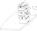
FIG. 1 is a schematic perspective view of an embodiment of the present invention;
FIG. 2 is a schematic diagram of a front view of an embodiment of the present invention;
FIG. 3 is a schematic sectional view taken along the line A-A in FIG. 2;
FIG. 4 is a schematic structural diagram of a lift driving mechanism according to an embodiment of the present invention;
FIG. 5 is a schematic structural view of a first translation drive mechanism in an embodiment of the present invention;
FIG. 6 is a schematic structural view of a first rotary drive mechanism in an embodiment of the present invention;
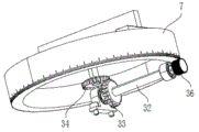
fig. 7 is a schematic structural view of a third rotary drive mechanism in the embodiment of the present invention.
Detailed Description
The utility model is further illustrated below with reference to the figures and examples. In the following detailed description, certain exemplary embodiments of the present invention are described by way of illustration only. Needless to say, a person skilled in the art realizes that the described embodiments can be modified in various different ways without departing from the spirit and scope of the present invention. Accordingly, the drawings and description are illustrative in nature and not intended to limit the scope of the claims.
As shown in fig. 1, the multi-degree-of-freedom auxiliary measuring platform for the roughness meter comprises a base 1, a lifting seat 2, a first translation seat 3, a second translation seat 4, a first rotating seat 5, a second rotating seat 6 and a third rotating seat 7 which are sequentially arranged from bottom to top, wherein the upper part of the third rotating seat 7 is fixedly connected with an installation seat 8 for installing the roughness meter, the lower part of the base 1 is fixedly connected with a reference seat 9, and the reference seat 9 extends horizontally to facilitate the positioning of a workpiece to be measured.
A lifting driving mechanism for driving the lifting seat 2 to lift up and down along the Z-axis direction is arranged between the lifting seat 2 and the base 1; a first translation driving mechanism and a first translation guiding mechanism which drive the first translation seat 3 to translate back and forth along the X-axis direction are arranged between the first translation seat 3 and the lifting seat 2; a second translation driving mechanism and a second translation guiding mechanism which drive the second translation seat 4 to translate left and right along the Y-axis direction are arranged between the second translation seat 4 and the first translation seat 3; a first rotation driving mechanism and a first rotation guiding mechanism which drive the first rotation base 5 to rotate by taking the Y-axis direction as the center are arranged between the first rotation base 5 and the second translation base 4; a second rotation driving mechanism and a second rotation guiding mechanism for driving the second rotation base 6 to rotate around the X-axis direction are arranged between the second rotation base 6 and the first rotation base 5; a third rotation driving mechanism for driving the third rotating base 7 to rotate around the Z-axis direction is disposed between the third rotating base 7 and the second rotating base 6.
Go up and down like this through lift seat 2, translation around first translation seat 3, translation and first roating seat 5 about second translation seat 4, the rotation of the not unidimensional of second roating seat 6 and third roating seat 7, can realize roughness appearance and adjust at the degree of freedom of all directions, thereby can adjust the measurement of the angle of roughness appearance in order to deal with more complicated structure part wantonly as required, adopt longitudinal arrangement's tower structure, overall structure design is succinct, pleasing to the eye, it is little to occupy installation space.
Referring to fig. 4, in this embodiment, the lifting driving mechanism includes an X-shaped lifting frame 10 (or called a scissor-type lifting frame), the upper end of the X-shaped lifting frame 10 is fixedly connected to the lifting base 2 through a mounting base 12, one side of the bottom of the X-shaped lifting frame 10 is connected to a lifting driving knob 11 through a screw pair 13, and the screw pair 13 drives the X-shaped lifting frame 10 to move up and down to lift the lifting base 2 by rotating the lifting driving knob 11. The lifting structure is a commonly known structure in the art, and will not be described herein again, and of course, other lifting structures may be adopted to achieve the lifting function of the lifting base 2, which all fall within the protection scope of the present invention.
Referring to fig. 2 and 5, in this embodiment, the first translation guide mechanism includes a first guide rail 14 fixedly disposed on the lifting base 2, and a first sliding slot 15 slidably engaged with the first guide rail 14 is disposed on the first translation base 3. First translation actuating mechanism includes first screw rod 16, the both ends of first screw rod 16 pass through the bearing rotate install in on the lift seat 2, fixed mounting have on the first translation seat 3 with first screw rod 16 complex first swivel nut 17, first knob 18 is installed to one of them tip of first screw rod 16, drives first screw rod 16 through rotatory first knob 18 and rotates, drives first swivel nut 17 translation around when first screw rod 16 rotates to realize first translation seat 3 and translate around along the X axle direction.
Referring to fig. 1 and 3, the second translational guide mechanism includes a second guide rail 19 fixedly disposed on the first translational seat 3, and a second sliding slot slidably engaged with the second guide rail 19 is disposed on the second translational seat 4; the second translation driving mechanism comprises a second screw 21 which is rotatably installed on the first translation base 3 through a bearing, a second threaded sleeve 22 which is matched with the second screw 21 is fixedly installed on the second translation base 4, a second knob 20 is installed at the end part of the second screw 21, and the second translation base 4 can translate left and right along the Y-axis direction by rotating the second knob 20.
Referring to fig. 1 and 6, the first rotary guiding mechanism includes a third guide rail 23 fixedly disposed on the second translating seat 4, the third guide rail 23 is in an arc design, a third sliding slot 24 slidably engaged with the third guide rail 23 is disposed on the first rotating seat 5, and the third sliding slot 24 is also in an arc design correspondingly; the first rotary driving mechanism comprises a first worm 25 which is rotatably installed on the second translation seat 4 through a bearing, a first worm wheel 26 which is meshed with the first worm 25 is fixedly installed on the first rotary seat 5, a third knob 27 is installed at one end of the first worm 25, the first worm 25 is driven to rotate through rotating the third knob 27, and the first worm 25 drives the first worm wheel 26 to rotate when rotating, so that the first rotary seat 5 is rotated.
Referring to fig. 1 and 3, the second rotary guiding mechanism includes a fourth guide rail 28 fixedly disposed on the first rotary base 5, and a fourth sliding slot slidably engaged with the fourth guide rail 28 is disposed on the second rotary base 6; the second rotary driving mechanism comprises a second worm 29 rotatably mounted on the first rotary base 5, a second worm wheel 30 meshed with the second worm 29 is fixedly mounted on the second rotary base 6, a fourth knob 31 is mounted at the end of the second worm 30, and the second rotary base 6 can rotate by rotating the fourth knob 31.
Referring to fig. 1 and 7, the third rotating base 7 is disc-shaped, the second rotating base 6 has a disc-shaped boss 35 that is in sleeve fit with the third rotating base 7, and the third rotating base 7 can rotate relative to the disc-shaped boss 35; the third rotary driving mechanism comprises a driving rod 32 which is rotatably installed on the disc-shaped boss 35 through a bearing, a driving bevel gear 33 is fixedly installed on the driving rod 32, a driven bevel gear 34 which is meshed with the driving bevel gear 33 is fixedly installed on the third rotary seat 7, a fifth knob 36 is installed at one end of the driving rod 32, the driving rod 32 is driven to rotate through rotating the fifth knob 36, the driving rod 32 drives the driving bevel gear 33 to rotate, and the driven bevel gear 34 is driven to rotate when the driving bevel gear 33 rotates, so that the third rotary seat 7 rotates.
As mentioned above, the relative moving parts are in sliding fit by adopting a guide rail structure, the structure is simple, and the working stability is good; the displacement regulating quantity is controlled by matching the knob with a transmission mechanism such as a screw pair or a gear pair, the precision is high, and the operation and the use are convenient.
The above description is only an exemplary embodiment of the present invention, and is not intended to limit the scope of the present invention. Such as a translation driving mechanism or a rotation driving mechanism, can be realized by other common structures, and any person skilled in the art can make equivalent changes and modifications without departing from the concept and principle of the present invention, and the present invention shall fall into the protection scope of the present invention.
Claims (10)
1. Roughness appearance multi freedom auxiliary measuring platform, its characterized in that: the device comprises a base, a lifting seat, a first translation seat, a second translation seat, a first rotating seat, a second rotating seat and a third rotating seat which are arranged from bottom to top in sequence;
a lifting driving mechanism for driving the lifting seat to lift up and down along the Z-axis direction is arranged between the lifting seat and the base;
a first translation driving mechanism and a first translation guiding mechanism which drive the first translation seat to translate back and forth along the X-axis direction are arranged between the first translation seat and the lifting seat;
a second translation driving mechanism and a second translation guiding mechanism which drive the second translation seat to translate left and right along the Y-axis direction are arranged between the second translation seat and the first translation seat;
a first rotation driving mechanism and a first rotation guiding mechanism which drive the first rotation base to rotate by taking the Y-axis direction as the center are arranged between the first rotation base and the second translation base;
a second rotation driving mechanism and a second rotation guiding mechanism which drive the second rotating seat to rotate by taking the X-axis direction as the center are arranged between the second rotating seat and the first rotating seat;
and a third rotary driving mechanism for driving the third rotary seat to rotate by taking the Z-axis direction as a center is arranged between the third rotary seat and the second rotary seat.
2. The roughness meter multiple degree of freedom auxiliary measuring platform of claim 1, wherein: and the upper part of the third rotating seat is fixedly connected with a mounting seat for mounting a roughness meter.
3. The roughness meter multiple degree of freedom auxiliary measuring platform of claim 1, wherein: the lower part of the base is fixedly connected with a reference seat.
4. The roughness meter multiple degree of freedom auxiliary measuring platform of claim 1, wherein: the lifting driving mechanism comprises an X-shaped lifting frame, and the X-shaped lifting frame is connected with a lifting driving knob.
5. The roughness meter multiple degree of freedom auxiliary measuring platform of claim 1, wherein: the first translation guide mechanism comprises a first guide rail fixedly arranged on the lifting seat, and a first sliding groove in sliding fit with the first guide rail is arranged on the first translation seat.
6. The roughness meter multiple degree of freedom auxiliary measuring platform of claim 5, wherein: the first translation driving mechanism comprises a first screw rod rotatably installed on the lifting seat, a first threaded sleeve matched with the first screw rod is fixedly installed on the first translation seat, and a first knob is installed at the end of the first screw rod.
7. The roughness meter multiple degree of freedom auxiliary measuring platform of claim 1, wherein: the second translation guide mechanism comprises a second guide rail fixedly arranged on the first translation seat, and a second sliding groove in sliding fit with the second guide rail is arranged on the second translation seat;
the second translation driving mechanism comprises a second screw rod rotatably mounted on the first translation seat, a second threaded sleeve matched with the second screw rod is fixedly mounted on the second translation seat, and a second knob is mounted at the end of the second screw rod.
8. The roughness meter multiple degree of freedom auxiliary measuring platform of claim 1, wherein: the first rotary guide mechanism comprises a third guide rail fixedly arranged on the second translation seat, and a third sliding groove in sliding fit with the third guide rail is arranged on the first rotary seat;
the first rotary driving mechanism comprises a first worm rotatably mounted on the second translation seat, a first worm wheel meshed with the first worm is fixedly mounted on the first rotation seat, and a third knob is mounted at the end of the first worm.
9. The roughness meter multiple degree of freedom auxiliary measuring platform of claim 1, wherein: the second rotary guide mechanism comprises a fourth guide rail fixedly arranged on the first rotary seat, and a fourth sliding groove in sliding fit with the fourth guide rail is arranged on the second rotary seat;
the second rotary driving mechanism comprises a second worm rotatably mounted on the first rotary base, a second worm wheel meshed with the second worm is fixedly mounted on the second rotary base, and a fourth knob is mounted at the end of the second worm.
10. The coarseness gauge multiple degree of freedom auxiliary measurement platform of any one of claims 1 to 9, wherein: the third rotary driving mechanism comprises a driving rod rotatably installed on the second rotary seat, a driving bevel gear is fixedly installed on the driving rod, a driven bevel gear meshed with the driving bevel gear is fixedly installed on the third rotary seat, and a fifth knob is installed at the end of the driving rod.
Priority Applications (1)
| Application Number | Priority Date | Filing Date | Title |
|---|---|---|---|
| CN202123127550.4U CN215639384U (en) | 2021-12-14 | 2021-12-14 | Roughness meter multi freedom auxiliary measuring platform |
Applications Claiming Priority (1)
| Application Number | Priority Date | Filing Date | Title |
|---|---|---|---|
| CN202123127550.4U CN215639384U (en) | 2021-12-14 | 2021-12-14 | Roughness meter multi freedom auxiliary measuring platform |
Publications (1)
| Publication Number | Publication Date |
|---|---|
| CN215639384U true CN215639384U (en) | 2022-01-25 |
Family
ID=79934903
Family Applications (1)
| Application Number | Title | Priority Date | Filing Date |
|---|---|---|---|
| CN202123127550.4U Active CN215639384U (en) | 2021-12-14 | 2021-12-14 | Roughness meter multi freedom auxiliary measuring platform |
Country Status (1)
| Country | Link |
|---|---|
| CN (1) | CN215639384U (en) |
-
2021
- 2021-12-14 CN CN202123127550.4U patent/CN215639384U/en active Active
Similar Documents
| Publication | Publication Date | Title |
|---|---|---|
| CN219734749U (en) | Multi-degree-of-freedom-adjustable computer display bracket | |
| CN101979953A (en) | Three-dimensional fine-adjustment worktable for thread scanning meter | |
| CN211504130U (en) | Engineering surveying instrument positioning device | |
| CN113063331A (en) | A position degree short-term test device for machining | |
| CN215639384U (en) | Roughness meter multi freedom auxiliary measuring platform | |
| CN219221786U (en) | Novel hanger for surveying instrument | |
| CN219853939U (en) | Multi-spindle horizontal calibration device of substrate glass grinding machine | |
| CN111486806A (en) | Application-end-based gear runout rapid detection mechanism and detection method thereof | |
| CN217403305U (en) | Shaft workpiece machining precision detection device | |
| CN214747635U (en) | High frock of measurement center | |
| CN213120581U (en) | Novel angle sensor assembly | |
| CN212903081U (en) | Bidirectional measuring contourgraph sensor | |
| CN206335578U (en) | Cutting robot lowering or hoisting gear | |
| CN112945056A (en) | High frock of measurement center | |
| CN219954840U (en) | Numerical control blade relief angle measurement auxiliary device | |
| CN213033877U (en) | Screw rod transmission mechanism, lifting device and ultrasonic welding machine | |
| CN107322544B (en) | Mechanical attitude adjusting system of wing root rib positioning tool | |
| CN218992259U (en) | Ball screw sliding table with accurate positioning capability | |
| CN220018435U (en) | Handiwork deformation detection device | |
| CN111958266B (en) | Precise guide rail for CNC (computer numerical control) machine tool | |
| CN218694943U (en) | Laser marking machine is adjusted to triaxial | |
| CN220764704U (en) | Assembly mechanism capable of rapidly adjusting installation posture of airplane | |
| CN215524546U (en) | Z-axis transmission balance adjusting device of three-coordinate measuring machine | |
| CN217305208U (en) | Eddy current sensor for measuring rotating speed | |
| CN219944985U (en) | Bearing device and processing equipment |
Legal Events
| Date | Code | Title | Description |
|---|---|---|---|
| GR01 | Patent grant | ||
| GR01 | Patent grant |