CN215600879U - Automatic monitoring device of electric substation - Google Patents
Automatic monitoring device of electric substation Download PDFInfo
- Publication number
- CN215600879U CN215600879U CN202122000931.XU CN202122000931U CN215600879U CN 215600879 U CN215600879 U CN 215600879U CN 202122000931 U CN202122000931 U CN 202122000931U CN 215600879 U CN215600879 U CN 215600879U
- Authority
- CN
- China
- Prior art keywords
- substation
- main body
- monitoring
- monitoring device
- heat dissipation
- Prior art date
- Legal status (The legal status is an assumption and is not a legal conclusion. Google has not performed a legal analysis and makes no representation as to the accuracy of the status listed.)
- Active
Links
Images
Landscapes
- Emergency Alarm Devices (AREA)
Abstract
The utility model discloses an automatic monitoring device for a substation, which comprises a damp-proof base, wherein a substation main body is fixed in the middle of the damp-proof base, a sun-proof ceiling is arranged at the top of the substation main body, first mounting blocks are symmetrically fixed in the middles of two ends of the sun-proof ceiling, one end of each first mounting block is provided with a first monitoring camera, an electric cabinet is fixed in the substation main body, and a temperature sensor is arranged at the inner side of the electric cabinet. The manual inspection is replaced, the related working data can be remotely acquired, and the operation and the control are simple and easy.
Description
Technical Field
The utility model relates to a monitoring management device, in particular to an automatic monitoring device for a substation, and belongs to the technical field of power equipment.
Background
The power substation is a place and place for changing voltage as the name implies, and is a place for converting, concentrating and distributing voltage and current of electric energy in a power system. In order to ensure the quality of electric energy and the safety of equipment, voltage regulation, control of the flow direction and distribution of voltage, current and power in each node and branch in a tidal current power system and protection of transmission and distribution lines and main electrical equipment are also required in a substation. It can be divided into electric power substation and traction substation according to application, and can be used for electric railway and electric car. A large number of high-voltage cabinets and low-voltage cabinets are stored in the substation, the high-voltage cabinets and the low-voltage cabinets detect various electric quantity data information, and the information needs to be periodically copied manually by an electrician in the past to prevent safety accidents such as overvoltage, overcurrent and overload from occurring, so that the safety of the substation is ensured.
The existing power transformation needs manual inspection, so that time and labor are wasted, the efficiency is low, and corresponding early warning processing cannot be immediately carried out when danger is about to occur, so that the safety of the power transformation substation cannot be effectively guaranteed. Therefore, the automation monitoring device for the substation is provided by improving the automation monitoring device for the substation.
SUMMERY OF THE UTILITY MODEL
The utility model aims to provide an automatic monitoring device for a substation, which aims to solve the problems that the traditional substation provided by the background technology needs manual detection, time and labor are wasted, the efficiency is low, and corresponding early warning treatment cannot be immediately carried out when danger is about to occur, so that the safety of the substation cannot be effectively ensured.
In order to achieve the purpose, the utility model provides the following technical scheme: an automatic monitoring device of a substation comprises a moisture-proof base, a substation main body is fixed in the middle of the moisture-proof base, the top of the substation main body is provided with a sun-proof ceiling, the middles of two ends of the sun-proof ceiling are symmetrically fixed with first mounting blocks, one end of the first mounting block is provided with a first monitoring camera, an electric cabinet is fixed in the main body of the substation, a temperature sensor is arranged on the inner side of the electric cabinet, the top of the electric power cabinet is electrically connected with a parameter display screen, the top of the inner side of the main body of the substation is fixedly connected with a monitoring host which is electrically connected with the electric power cabinet, one end of the monitoring host is provided with a data acquisition terminal, the other end of the monitoring host is provided with a signal receiving and transmitting terminal, the transformer substation is characterized in that a heat dissipation plate is arranged in the middle of one side of the transformer substation main body, a mounting port is formed in the middle of the heat dissipation plate, and a heat dissipation fan is fixedly connected in the mounting port.
As a preferred technical solution of the present invention, a second mounting block is disposed in the middle of one side of the monitoring host, a second monitoring camera is fixed to one end of the second mounting block, and the second monitoring camera and the first monitoring camera are electrically connected to the monitoring host.
As a preferable technical scheme of the utility model, a supporting plate is vertically fixed between the top of the outer side of the substation main body and the sun-proof ceiling.
As a preferred technical scheme of the utility model, the top of the outer side of the heat dissipation plate is rotatably connected with a protective cover corresponding to the heat dissipation fan through a damping rotating shaft, and the middle of the bottom end of the protective cover is provided with an air hole.
As a preferable technical scheme of the utility model, the inner wall of the substation main body is provided with a flame-retardant layer.
As a preferred technical scheme of the utility model, the temperature sensor is a product of QAC22 type.
Compared with the prior art, the utility model has the beneficial effects that: the automatic monitoring device for the power substation has the advantages that manual detection is not needed, time and labor are saved, corresponding early warning processing can be timely carried out when danger is about to occur, and safety of the power substation is guaranteed.
Drawings
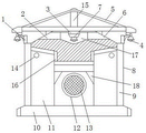
FIG. 1 is a schematic view of the overall structure of the present invention;
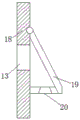
FIG. 2 is a schematic view of the heat dissipation plate of the present invention;
in the figure: 1. a first mounting block; 2. a data acquisition terminal; 3. a second mounting block; 4. a first surveillance camera; 5. a sun-proof ceiling; 6. a signal transceiving terminal; 7. a second surveillance camera; 8. a substation main body; 9. a flame retardant layer; 10. a moisture-proof base; 11. an electric power cabinet; 12. an installation port; 13. a heat radiation fan; 14. a temperature sensor; 15. a support plate; 16. a parameter display screen; 17. monitoring the host; 18. a heat dissipation plate; 19. a protective cover; 20. and (4) air holes.
Detailed Description
The technical solutions in the embodiments of the present invention will be clearly and completely described below with reference to the drawings in the embodiments of the present invention, and it is obvious that the described embodiments are only a part of the embodiments of the present invention, and not all of the embodiments. All other embodiments, which can be derived by a person skilled in the art from the embodiments given herein without making any creative effort, shall fall within the protection scope of the present invention.
Referring to fig. 1-2, the present invention provides an automatic monitoring device for a substation, which includes a moisture-proof base 10, a substation main body 8 is fixed in the middle of the moisture-proof base 10, a sun-proof ceiling 5 is arranged on the top of the substation main body 8, first mounting blocks 1 are symmetrically fixed in the middle of two ends of the sun-proof ceiling 5, a first monitoring camera 4 is arranged at one end of each first mounting block 1, a power cabinet 11 is fixed in the substation main body 8, a temperature sensor 14 is installed inside the power cabinet 11, a parameter display screen 16 is electrically connected to the top of the power cabinet 11, a monitoring host 17 electrically connected to the power cabinet 11 is fixedly connected to the top of the inner side of the substation main body 8, a data acquisition terminal 2 is arranged at one end of the monitoring host 17, a signal transceiving terminal 6 is arranged at the other end of the monitoring host 17, a heat dissipation plate 18 is arranged in the middle of one side of the substation main body 8, the middle of the heat dissipation plate 18 is provided with a mounting port 12, and a heat dissipation fan 13 is fixedly connected in the mounting port 12.
Preferably, the middle of one side of the monitoring host 17 is provided with a second mounting block 3, one end of the second mounting block 3 is fixed with a second monitoring camera 7, and the second monitoring camera 7, the first monitoring camera 4 and the monitoring host 17 are electrically connected, so that the internal environment change of the substation can be detected in real time.
And a support plate 15 is vertically fixed between the top of the outer side of the substation main body 8 and the sun-proof ceiling 5, so that the installation stability of the sun-proof ceiling 5 is improved.
The top of the outer side of the heat dissipation plate 18 is rotatably connected with a protective cover 19 corresponding to the heat dissipation fan 13 through a damping rotating shaft, and the middle of the bottom end of the protective cover 19 is provided with an air hole 20 to prevent dust from entering the mounting opening 12.
The inner wall of the substation main body 8 is provided with a flame-retardant layer 9, so that the fireproof and flame-retardant performance of the substation main body 8 is improved.
The temperature sensor 14 is a product of QAC22 type, and can control the environmental temperature change in the substation in time.
When the automatic monitoring device is used, manual detection is not needed, time and labor are saved, corresponding early warning processing can be timely carried out when danger is about to occur, and safety of the substation is guaranteed.
In the description of the present invention, it is to be understood that the indicated orientations or positional relationships are based on the orientations or positional relationships shown in the drawings and are only for convenience in describing the present invention and simplifying the description, but are not intended to indicate or imply that the indicated devices or elements must have a particular orientation, be constructed and operated in a particular orientation, and are not to be construed as limiting the present invention.
In the present invention, unless otherwise explicitly specified or limited, for example, it may be fixedly attached, detachably attached, or integrated; can be mechanically or electrically connected; the terms may be directly connected or indirectly connected through an intermediate, and may be communication between two elements or interaction relationship between two elements, unless otherwise specifically limited, and the specific meaning of the terms in the present invention will be understood by those skilled in the art according to specific situations.
Although embodiments of the present invention have been shown and described, it will be appreciated by those skilled in the art that changes, modifications, substitutions and alterations can be made in these embodiments without departing from the principles and spirit of the utility model, the scope of which is defined in the appended claims and their equivalents.
Claims (5)
1. The automatic monitoring device for the power substation comprises a damp-proof base (10) and is characterized in that a power substation main body (8) is fixed in the middle of the damp-proof base (10), a sun-proof ceiling (5) is arranged at the top of the power substation main body (8), first installation blocks (1) are symmetrically fixed in the middle of two ends of the sun-proof ceiling (5), a first monitoring camera (4) is arranged at one end of each first installation block (1), a power cabinet (11) is fixed inside the power substation main body (8), a temperature sensor (14) is installed on the inner side of the power cabinet (11), a parameter display screen (16) is electrically connected to the top of the power cabinet (11), a monitoring host (17) electrically connected with the power cabinet (11) is fixedly connected to the inner top of the power substation main body (8), and a data acquisition terminal (2) is arranged at one end of the monitoring host (17), the monitoring system is characterized in that a signal receiving and sending terminal (6) is arranged at the other end of the monitoring host (17), a heat dissipation plate (18) is arranged in the middle of one side of the substation main body (8), a mounting hole (12) is formed in the middle of the heat dissipation plate (18), and a heat dissipation fan (13) is fixedly connected in the mounting hole (12).
2. A substation automation monitoring device according to claim 1, characterized in that: the monitoring system is characterized in that a second mounting block (3) is arranged in the middle of one side of the monitoring host (17), one end of the second mounting block (3) is fixed with a second monitoring camera (7), and the second monitoring camera (7), the first monitoring camera (4) and the monitoring host (17) are electrically connected.
3. A substation automation monitoring device according to claim 1, characterized in that: and a support plate (15) is vertically fixed between the top of the outer side of the substation main body (8) and the sun-proof ceiling (5).
4. A substation automation monitoring device according to claim 1, characterized in that: the top of the outer side of the heat dissipation plate (18) is rotatably connected with a protective cover (19) corresponding to the heat dissipation fan (13) through a damping rotating shaft, and an air hole (20) is formed in the middle of the bottom end of the protective cover (19).
5. A substation automation monitoring device according to claim 1, characterized in that: and a flame-retardant layer (9) is arranged on the inner wall of the substation main body (8).
Priority Applications (1)
| Application Number | Priority Date | Filing Date | Title |
|---|---|---|---|
| CN202122000931.XU CN215600879U (en) | 2021-08-24 | 2021-08-24 | Automatic monitoring device of electric substation |
Applications Claiming Priority (1)
| Application Number | Priority Date | Filing Date | Title |
|---|---|---|---|
| CN202122000931.XU CN215600879U (en) | 2021-08-24 | 2021-08-24 | Automatic monitoring device of electric substation |
Publications (1)
| Publication Number | Publication Date |
|---|---|
| CN215600879U true CN215600879U (en) | 2022-01-21 |
Family
ID=79882872
Family Applications (1)
| Application Number | Title | Priority Date | Filing Date |
|---|---|---|---|
| CN202122000931.XU Active CN215600879U (en) | 2021-08-24 | 2021-08-24 | Automatic monitoring device of electric substation |
Country Status (1)
| Country | Link |
|---|---|
| CN (1) | CN215600879U (en) |
-
2021
- 2021-08-24 CN CN202122000931.XU patent/CN215600879U/en active Active
Similar Documents
| Publication | Publication Date | Title |
|---|---|---|
| CN207819229U (en) | One kind being used for distributed energy storage power station container | |
| CN102437646A (en) | Wireless temperature and humidity monitoring device for high-voltage switch cabinet | |
| CN106058702A (en) | Modular intelligent box type substation | |
| CN209805362U (en) | Novel energy-saving wind power type bus duct | |
| CN202309221U (en) | Wireless temperature and humidity monitoring device for high-voltage switch cabinets | |
| CN215600879U (en) | Automatic monitoring device of electric substation | |
| CN210723900U (en) | Centralized ammeter case convenient to management and control just have power compensation function | |
| CN203588057U (en) | Wind power monitoring device | |
| CN105552730A (en) | Intelligent comprehensive power distribution box | |
| CN206135279U (en) | Modular intelligent box -type substation | |
| CN205666497U (en) | Block terminal is synthesized to intelligent electric wire netting | |
| CN210041077U (en) | Intelligent monitoring mobile box type transformer system | |
| CN211126719U (en) | Testing and adjusting integrated power distribution terminal | |
| CN211320628U (en) | Low-voltage complete switch cabinet body | |
| CN210838611U (en) | Municipal administration safety block terminal | |
| CN210926634U (en) | Safe type high-low voltage power distribution cabinet | |
| CN207664490U (en) | A kind of Intelligent high-tension switch cabinet | |
| CN215989847U (en) | Box-type power converter with automatic alarm function | |
| CN214044412U (en) | Signal acquisition screen cabinet, signal acquisition system and monitoring system for SF6 gas densitometer | |
| CN217115216U (en) | High tension switchgear with remote monitoring and automatic electric leakage monitoring | |
| CN210273099U (en) | High-voltage multilayer switch cabinet | |
| CN217769598U (en) | Intelligent control system of high tension switchgear under forceful electric power interference | |
| CN219247534U (en) | On-line low-voltage protection device | |
| CN210350604U (en) | Novel intelligent environmental protection gas insulation looped netowrk cabinet | |
| CN216215402U (en) | Modular intelligent low-voltage draw-out type switch cabinet |
Legal Events
| Date | Code | Title | Description |
|---|---|---|---|
| GR01 | Patent grant | ||
| GR01 | Patent grant |