CN215581270U - Multifunctional portable mobile phone telescopic support - Google Patents
Multifunctional portable mobile phone telescopic support Download PDFInfo
- Publication number
- CN215581270U CN215581270U CN202121936796.3U CN202121936796U CN215581270U CN 215581270 U CN215581270 U CN 215581270U CN 202121936796 U CN202121936796 U CN 202121936796U CN 215581270 U CN215581270 U CN 215581270U
- Authority
- CN
- China
- Prior art keywords
- box body
- mobile phone
- connecting plate
- support
- tray
- Prior art date
- Legal status (The legal status is an assumption and is not a legal conclusion. Google has not performed a legal analysis and makes no representation as to the accuracy of the status listed.)
- Active
Links
Images


Abstract
A multifunctional portable mobile phone telescopic support relates to the technical field of mobile phone supports and comprises a support body worn on a person and a card body fixed on the back of a mobile phone; the bracket body comprises a box body and two parallel telescopic rods which are arranged in the box body and can simultaneously extend outwards from one end of the box body, one ends of the two telescopic rods are fixedly connected with a support, the support is hinged with a connecting plate for connecting a clamping body, and the connecting plate can be turned to be attached to the box body; the fixing body comprises a fixing tray and a limiting ring, the fixing tray is used for being bonded on the back of the mobile phone, the limiting ring is hinged on the fixing tray, and the fixing tray is rotatably connected with a blocking piece. The utility model can fix the mobile phone at the waist, is convenient to carry and does not occupy a pocket, or can be fixed at the wrist and can move the mobile phone to the palm position for use, and the arm can be relaxed in the using process.
Description
Technical Field
The utility model relates to the technical field of mobile phone supports, in particular to a multifunctional portable mobile phone telescopic support.
Background
Nowadays, mobile phones have become indispensable mobile communication equipment in people's daily life, and the mode of carrying of cell-phone at present mainly is put in the package or in the clothes pocket, easily misses telephone, information in putting in the package, and it is inconvenient to take, and easy stolen to put in the clothes pocket, and in crowded environment (such as subway, public transit and train etc.), still be convenient for draw the cell-phone from the pocket, it has a lot of inconvenient vexation to see all to have.
Some existing wrist-worn mobile phone supports can solve the problem that the mobile phone is inconvenient to carry, but the mobile phone supports are fixed in a manner similar to a wrist watch, so that in the use process, people need to look at the mobile phone by the action of looking at the watch with the back of the hand facing upwards, which is actually contrary to the hand posture (with the palm facing upwards) when people look at the mobile phone in the practical use, so that the mobile phone is difficult to avoid and has uncomfortable feeling in use, and even if the mobile phone is fixed in the direction of the inner surface of the wrist, the wrist needs to be lifted and moved to the front of eyes to watch the mobile phone in use, compared with the action of normally using the mobile phone (namely moving the palm to the front of the eyes), the mobile phone can excessively move the arm, so that the arm is twisted and stiff in action, and the arm is easily subjected to acid and fatigue.
SUMMERY OF THE UTILITY MODEL
The utility model aims to provide a multifunctional portable mobile phone telescopic support which can fix a mobile phone at the waist, is convenient to carry and does not occupy a pocket, or is fixed at the wrist, can move the mobile phone to the palm position or be used at a long distance, and can enable the arm to be relaxed in the using process.
In order to solve the technical problems, the utility model adopts the following technical scheme: a multifunctional portable mobile phone telescopic support comprises a support body worn on a human body and a card body fixed on the back of a mobile phone; the bracket body comprises a box body and two parallel telescopic rods which are arranged in the box body and can simultaneously extend outwards from one end of the box body, one ends of the two telescopic rods are fixedly connected with a support, the support is hinged with a connecting plate for connecting a clamping body, and the connecting plate can be turned to be attached to the box body; the fixing body comprises a fixed tray which is used for being adhered to the back of the mobile phone and a limiting ring which is hinged on the fixed tray, two blocking pieces are rotatably connected on the fixed tray, a magnet is arranged in the fixed tray, the limiting ring is lapped on the fixed tray and can be attracted by the magnet, the limiting ring pushes the two blocking pieces, so that the blocking pieces extend outwards from the edge of the fixed tray, a torsion spring is connected between the blocking pieces and the fixed tray, under the action of the torsion spring, the inner sides of the blocking pieces can be abutted against the limiting ring lapped on the fixed tray, through holes which are matched with the fixed tray are formed in the connecting plate, two positioning grooves are formed in the inner wall of each through hole at intervals, a positioning block which can be matched with the positioning grooves is correspondingly arranged on the outer sides of the blocking pieces, and the fixed tray can be sleeved by the connecting plate through the through holes, when the through hole is matched with the fixed tray, the limiting ring can be pressed on the connecting plate and enable the edge part of the blocking piece extending out of the fixed tray to abut against the connecting plate, so that the connecting plate is fixed on the back of the mobile phone; the bottom of the box body is detachably connected with a clamp for clamping a waistband or the two sides of the box body are detachably connected with wristbands.
Preferably, the telescopic rod comprises a plurality of stretching tubes which are sleeved layer by layer.
More preferably, one end of the connecting plate is fixedly provided with a connecting block which is inserted into the support and can turn over in the support, and an adjusting bolt for fastening the connecting block is arranged between the support and the connecting block in a penetrating manner.
More preferably, the bottom surface of the box body is provided with a dovetail groove, one end of the dovetail groove extends to the front end of the bottom surface of the box body, and the clamp is provided with a bolt type sliding block which can be clamped in the dovetail groove.
More preferably, the fixed bar inserted block that is provided with in the rear end at the box body back, the fixed link plate that is provided with in the front end at the box body back, the one end of clip is corresponding to be seted up with bar inserted block assorted bar jack, the other end of clip articulates there is the link that draws that can hang the link plate, will the bar inserted block inserts in the bar jack, and makes draw the link to hang the link plate, thereby can make form the angle between box body and the clip.
More preferably, the surface of the clamp is provided with a clamping groove for clamping and hiding the pull hanging ring.
More preferably, the one side of fixed tray is provided with the viscose layer, the middle part of fixed tray is provided with rotatable stand bolt, a through-hole has been seted up on the stand bolt, the spacing ring is equipped with the breach, is located the spacing ring end of breach department can insert in the through-hole.
More preferably, the wristband is a woven wristband.
The utility model has the beneficial effects that: when the box body is connected with the clip, the clip can be hung on the waistband, and the mobile phone is fixed on the connecting plate through the clamping body, so that the mobile phone is convenient to carry and does not occupy a pocket; when the clip is detached from the box body, the mobile phone telescopic bracket can be worn on the wrist part, and the box body is arranged in the direction of the inside of the wrist, then the connecting plate can be turned over and opened, the card fixing body on the back of the mobile phone is clamped on the connecting plate for use, then the mobile phone can be dragged, and the telescopic rod begins to be stretched at the moment, so that the mobile phone can be used after being moved to the palm or the required position, which is more convenient, and at the moment, because the placing posture of the arm is almost the same as that of the original hand-held mobile phone, people can better adapt to the posture (or a plurality of postures), thereby relieving the feeling of soreness and fatigue of the arms, and after the use, if the left wrist (right wrist) is leaned on the mobile phone support, the left finger (right finger) can be used to directly push the mobile phone back, the mobile phone can be temporarily stored at the wrist part, so that great convenience can be provided in the carrying process; in addition, because the quantity of telescopic link is two, consequently need not to set up the telescopic link comparatively sturdy and guarantee intensity like setting up a telescopic link alone, so the box body can be made thinly to make whole cell-phone telescopic bracket's structure smaller and more exquisite, pleasing to the eye and portable.
In addition, the length of the telescopic rod can be adjusted to be longer in the using process, so that the mobile phone can keep a certain distance from the eyes, and the eyesight of the eyes is protected; when the mobile phone is worn on the hand and stored, the hands can be easily released, so that the hands can do other things without holding the mobile phone in the hands, for example, in the process of dancing a square in summer, the mobile phone can be fixed on the wrist by using the support due to the absence of a backpack or even a proper pocket; the mobile phone can be worn on the wrist in the playing process, so that the mobile phone can see messages on the mobile phone in time when two hands are freed to play.
Drawings
FIG. 1 is a schematic view of the overall structure of a stent body according to an embodiment of the present invention;
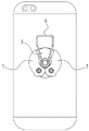
fig. 2 is a schematic view of the overall structure of the embodiment of the present invention when the fastening body is mounted on the back of the mobile phone (when the baffle plate avoids the limiting ring);
FIG. 3 is a schematic structural diagram of the embodiment when the bracket body and the fastening body are connected (when the stop plate blocks the stop ring);
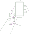
FIG. 4 is a schematic view of the mobile phone telescopic bracket of the embodiment when the mobile phone is worn on the wrist after being fixed and extended to the palm for use;
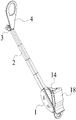
FIG. 5 is a schematic diagram of the mobile phone telescopic bracket fixed to the waist of the mobile phone, followed by inclining the box body, inserting the strip-shaped insertion block into the strip-shaped insertion slot, hanging the hanging plate by the pull-hanging ring, extending the telescopic rod, and adjusting the orientation angle of the connecting plate in the embodiment;
FIG. 6 is a schematic diagram of the back structure of the case in the embodiment;
FIG. 7 is a schematic view showing the structure of a clip according to the embodiment;
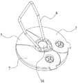
FIG. 8 is a schematic structural view of a fixing tray, a retaining ring and a stud according to an embodiment;
fig. 9 is a schematic view showing the bracket body hung on the hook in the embodiment.
The reference signs are:
1-box body 2-expansion link 3-support
4-connecting plate 4 a-positioning slot 5-fixing tray
6-limiting ring 7-catch 7 a-positioning block
8-adjusting bolt 9-dovetail groove 10-bolt type slide block
11-strip-shaped insertion block 12-hanging plate 13-strip-shaped insertion hole
14-pulling hanging ring 15-clamping groove 16-upright post bolt
18-clip 19-wrist strap.
Detailed Description
In order to facilitate understanding of those skilled in the art, the present invention will be further described with reference to the following examples and drawings, which are not intended to limit the present invention.
It should be noted that, unless otherwise explicitly stated or limited, the terms "mounted," "connected," "fixed," and the like are used broadly in the present invention, and may be, for example, fixedly connected, detachably connected, or integrally connected; they may be connected directly or indirectly through intervening media, or they may be interconnected between two elements. The specific meanings of the above terms in the present invention can be understood by those skilled in the art according to specific situations.
Further, in the present invention, unless otherwise expressly specified or limited, the first feature "on" or "under" the second feature may comprise the first and second features being in direct contact, or may comprise the first and second features being in contact, not in direct contact, but via another feature in between. Also, the first feature being "on," "above" and "over" the second feature includes the first feature being directly on and obliquely above the second feature, or merely indicating that the first feature is at a higher level than the second feature. A first feature being "under," "below," and "beneath" a second feature includes the first feature being directly under and obliquely below the second feature, or simply meaning that the first feature is at a lesser elevation than the second feature. The terms "upper", "lower", "front", "rear", "left", "right", "vertical", "horizontal", "top", "bottom", "inner", "outer", and the like, indicate orientations or positional relationships based on those shown in the drawings, and are only for convenience in describing and simplifying the description, but do not indicate or imply that the device or element referred to must have a particular orientation, be constructed and operated in a particular orientation, and thus, should not be construed as limiting the utility model.
As shown in fig. 1 to 8, the multifunctional portable mobile phone telescopic bracket includes a bracket body for wearing on a person and a card body for fixing on the back of a mobile phone; the bracket body comprises a box body 1 and two parallel telescopic rods 2 which are arranged in the box body 1 and can simultaneously extend outwards from one end of the box body 1, one ends of the two telescopic rods 2 are fixedly connected with a support 3, the support 3 is hinged with a connecting plate 4 for connecting a clamping body, and the connecting plate 4 can be turned over to be attached to the box body 1; the clamping body comprises a fixed tray 5 adhered to the back of the mobile phone and a limit ring 6 hinged on the fixed tray 5, two blocking pieces 7 are rotatably connected on the fixed tray 5, a magnet is arranged in the fixed tray 5, the limit ring 6 is arranged on the fixed tray 5, the limit ring 6 can be attracted by the magnet, and the limit ring 6 pushes the two blocking pieces 7, so that the blocking pieces 7 extend outwards from the edge of the fixed tray 5, a torsion spring (not shown in the drawing) is connected between the blocking pieces 7 and the fixed tray 5, under the action of the torsion spring, the inner side of the blocking piece 7 can be tightly propped against the limit ring 6 arranged on the fixed tray 5, a through hole matched with the fixed tray 5 is arranged on the connecting plate 4, two positioning grooves 4a are arranged on the inner wall of the through hole at intervals, a positioning block 7a capable of being matched with the positioning grooves 4a is correspondingly arranged on the outer side of the blocking piece 7, the connecting plate 4 can sleeve the fixed tray 5 through the through hole, the connecting plate 4 is rotated, so that the positioning groove 4a and the positioning block 7a can be staggered, when the through hole is matched with the fixed tray 5, the limiting ring 6 can be pressed on the connecting plate 4, and the edge part of the baffle 7 extending out of the fixed tray 5 is pressed on the connecting plate 4, so that the connecting plate 4 is fixed on the back of the mobile phone; the bottom of the box body 1 is detachably connected with a clamp 18 for clamping a waistband or both sides of the box body 1 are detachably connected with wrist straps 19.
The multifunctional portable mobile phone telescopic support provided by the embodiment can be wholly folded when not in use as a mobile phone does not need to be installed, the connecting plate 4 is turned over to be attached to the box body 1 to form the structural shape shown in figure 1, when the mobile phone needs to be installed, the mobile phone support can be worn on the wrist part, the box body 1 is arranged in the direction of the inside of the wrist, then the connecting plate 4 can be turned over and opened, the clamping body on the back of the mobile phone is clamped on the connecting plate 4 for use, then the mobile phone can be dragged, the telescopic rod 2 is stretched at the moment, so that the mobile phone can be used when being moved to the palm or the required position (shown in figure 4), and at the moment, the placing posture of the arm is almost the same as the placing posture of the original mobile phone when being held by hand, so that people can better adapt to the posture (or multiple postures) and further relieve the feeling of the arm, after the mobile phone is used, if the left wrist (right wrist) is worn by the mobile phone support, the mobile phone can be directly pushed back by using the fingers of the left hand (right fingers), and the mobile phone can be temporarily stored at the wrist part, so that great convenience can be provided in the carrying process; in addition, because the quantity of telescopic link 2 is two, consequently need not to set up the telescopic link comparatively sturdily and guarantee intensity like setting up a telescopic link alone, so the box body can be made thinly to make whole cell-phone telescopic bracket's structure smaller and more exquisite, pleasing to the eye and portable.
The multifunctional portable mobile phone telescopic support can be worn by a wrist or a waist, placed on a table or a vehicle, or used in various ways such as a key buckle.
Moreover, still can hand box body 1 and tensile telescopic link 2 to make this cell-phone telescopic bracket become from rapping bar usefulness, perhaps directly place box body 1 on the plane and use or watch the cell-phone (for example put on indoor desktop watch contents such as video, news, novels or put in the car and join in marriage in addition the couple and watch the navigation content), it is very practical and convenient, of course, trompil in the one end of clip 18, and hang the iron wire couple in air outlet fence department in the car, as shown in fig. 9, can hang clip 18 on the iron wire couple, thereby hang whole cell-phone telescopic bracket in the car fast.
It should be noted that, as will be known by those skilled in the art, in order to ensure the stability of the connection plate 4 after being turned over, a connection block that is inserted into the support 3 and can be turned over in the support 3 may be fixedly disposed at one end of the connection plate 4, an adjusting bolt 8 for fastening the connection block is inserted between the support 3 and the connection block, and after the connection plate 4 is turned over to any angle, the connection plate 4 may be kept in a fixed posture by screwing the adjusting bolt.
Preferably, the telescopic rod 2 comprises a plurality of stretching tubes which are nested layer by layer.
In this embodiment, the bottom surface of the box body 1 is provided with the dovetail groove 9, one end of the dovetail groove 9 extends to the front end of the bottom surface of the box body 1, the clip 18 is provided with the bolt type slide block 10 which can be clamped in the dovetail groove 9, the connecting structure is convenient to disassemble and assemble, and the connecting firmness is good, wherein the number of the dovetail grooves 9 and the bolt type slide block 10 is two.
Further, a bar-shaped inserting block 11 is fixedly arranged at the rear end of the back of the box body 1, a hanging plate 12 is fixedly arranged at the front end of the back of the box body 1, one end of a clamp 18 is correspondingly provided with a bar-shaped inserting hole 13 matched with the bar-shaped inserting block 11, the other end of the clamp 18 is hinged with a pulling hanging ring 15 capable of hanging the hanging plate 12, the bar-shaped inserting block 11 is inserted into the bar-shaped inserting hole 13, and the pulling hanging ring 14 is hung on the hanging plate 12, so that an angle can be formed between the box body 1 and the clamp 18, when the clamp 18 is used for clamping on a waistband of a person, the telescopic rod 2 is extended out and the connecting plate 4 is adjusted to a proper angle, so that the mobile phone can be moved to the front side of the face and keep a certain distance with the face, self-shooting, direct seeding, navigation and other operations can be carried out in the walking moving process by utilizing the mode, meanwhile, two hands can be released, the fatigue is effectively reduced, and the sanitation workers can also be conveniently used, compare in current through lifting from rapping bar or support with the hand and carrying out autodyne, live operation such as and cause the tired problem of hand ache, the flexible support of cell-phone of this embodiment can effectively solve these problems to can let the user relax more freely, can make people look the screen remotely above all, the health of protection eyes.
Preferably, the surface of the clip 18 is provided with a slot 15 for receiving and hiding the pull ring 14, and when the above function is not used, the pull ring 14 can be received in the slot 15, so that the connection of the clip 18 and the case 1 is not affected.
In addition, the one side of fixed tray 5 is provided with the viscose layer, and the middle part of fixed tray 5 is provided with rotatable stand bolt 16, has seted up a through-hole on the stand bolt 16, and spacing ring 6 is equipped with the breach, and the spacing ring 6 end that is located breach department can be inserted in the through-hole, two arc walls 17 have been seted up to the another side symmetry of fixed tray 5, and arc wall 17 can supply half ring body card of the spacing ring 6 that corresponds to go into. In the in-service use process, when assembling connecting plate 4 and fixed tray 5, can overturn earlier spacing ring 6 to sticking up, then spacing ring 6 can pass the through-hole on the connecting plate 4, after fixed tray 5 blocks in the through-hole, then can overturn spacing ring 6 down, make spacing ring 6 press on connecting plate 4, and simultaneously, separation blade 7 that is pushed up by spacing ring 6 also has a part to block connecting plate 4, avoid spacing ring 6 not hard up, and, after fixed tray 5 blocks in the through-hole, still can rotate in the through-hole, thereby the angle of light adjustment cell-phone.
Finally, in this embodiment, wrist strap 19 is for weaving the wrist strap, the both sides of box body 1 are provided with the protruding connecting portion of similar wrist-watch main part both sides, protruding connecting portion set up porosely to in cooperation joint with the thimble at 19 both ends of wrist strap, this part is because similar with current wrist-watch structure, consequently do not give unnecessary details, but most importantly wrist strap 19 adopts to weave the wrist strap and makes, can easily deform, fold, this makes this cell-phone telescopic bracket when passing through clip 18 card on the waistband, wrist strap 19 also need not additionally to dismantle, very big use of having made things convenient for.
The above embodiments are preferred implementations of the present invention, and the present invention can be implemented in other ways without departing from the spirit of the present invention.
Some of the drawings and descriptions of the present invention have been simplified to facilitate the understanding of the improvements over the prior art by those skilled in the art, and some other elements have been omitted from this document for the sake of clarity, and it should be appreciated by those skilled in the art that such omitted elements may also constitute the subject matter of the present invention.
Claims (8)
1. Multi-functional portable cell-phone telescopic bracket, its characterized in that: comprises a bracket body which is worn on a human body and a card solid body which is fixed on the back of the mobile phone;
the support body comprises a box body (1) and two parallel telescopic rods (2) which are arranged in the box body (1) and can extend outwards from one end of the box body (1) at the same time, one ends of the two telescopic rods (2) are fixedly connected with a support (3), the support (3) is hinged with a connecting plate (4) for connecting a clamping body, and the connecting plate (4) can be turned to be attached to the box body (1);
the fixing body comprises a fixing tray (5) adhered to the back of the mobile phone and a limiting ring (6) hinged to the fixing tray (5), the fixing tray (5) is rotatably connected with two blocking pieces (7), a magnet is arranged in the fixing tray (5), the limiting ring (6) is lapped on the fixing tray (5), the limiting ring (6) can be attracted by the magnet, the limiting ring (6) pushes the two blocking pieces (7) to enable the blocking pieces (7) to extend outwards from the edge of the fixing tray (5), a torsion spring is connected between the blocking pieces (7) and the fixing tray (5), under the action of the torsion spring, the inner side of each blocking piece (7) can be abutted against the limiting ring (6) lapped on the fixing tray (5), and a through hole matched with the fixing tray (5) is formed in the connecting plate (4), two positioning grooves (4 a) are arranged on the inner wall of the through hole at intervals, a positioning block (7 a) which can be matched with the positioning grooves (4 a) is correspondingly arranged on the outer side of the blocking piece (7), the connecting plate (4) can be sleeved on the fixed tray (5) through the through hole, the connecting plate (4) is rotated to enable the positioning grooves (4 a) and the positioning blocks (7 a) to be staggered, when the through hole is matched with the fixed tray (5), the limiting ring (6) can be pressed on the connecting plate (4) and enable the edge part of the blocking piece (7) extending out of the fixed tray (5) to be pressed on the connecting plate (4) so that the connecting plate (4) is fixed on the back of the mobile phone;
the bottom of the box body (1) is detachably connected with a clip (18) used for clamping a waistband or the two sides of the box body (1) are detachably connected with wristbands (19).
2. The multi-functional portable handset telescoping support of claim 1, wherein: the telescopic rod (2) comprises a plurality of stretching pipes which are sleeved layer by layer.
3. The multi-functional portable cell phone telescopic bracket of claim 2, characterized in that: the connecting plate is characterized in that one end of the connecting plate (4) is fixedly provided with a connecting block which is inserted into the support (3) and can be turned in the support (3), and an adjusting bolt (8) used for fastening the connecting block is arranged between the support (3) and the connecting block in a penetrating manner.
4. The multi-functional portable handset telescoping support of claim 1, wherein: the bottom surface of the box body (1) is provided with a dovetail groove (9), one end of the dovetail groove (9) extends to the front end of the bottom surface of the box body (1), and the clamp (18) is provided with a bolt type sliding block (10) which can be clamped into the dovetail groove (9).
5. The multi-functional portable cell phone telescoping stand of claim 4, characterized in that: the rear end at the box body (1) back is fixed and is provided with bar inserted block (11), the front end at the box body (1) back is fixed and is provided with link plate (12), the one end correspondence of clip (18) is seted up with bar inserted block (11) assorted bar jack (13), the other end of clip (18) articulates has link (14) of drawing that can hang link plate (12), will bar inserted block (11) insert in bar jack (13), and makes link (14) are drawn and link plate (12) are hung, thereby can make form the angle between box body (1) and clip (18).
6. The multi-functional portable cell phone telescoping stand of claim 5, characterized in that: the surface of the clamp (18) is provided with a clamping groove (15) for clamping and hiding the pull hanging ring (14).
7. The multi-functional portable handset telescoping support of claim 1, wherein: one side of the fixed tray (5) is provided with an adhesive layer, the middle part of the fixed tray (5) is provided with a rotatable upright post bolt (16), a through hole is formed in the upright post bolt (16), a notch is formed in the limiting ring (6), and the end of the limiting ring (6) at the notch can be inserted into the through hole.
8. The multi-functional portable handset telescoping support of claim 1, wherein: the wrist band (19) is a woven wrist band.
Priority Applications (1)
| Application Number | Priority Date | Filing Date | Title |
|---|---|---|---|
| CN202121936796.3U CN215581270U (en) | 2021-08-18 | 2021-08-18 | Multifunctional portable mobile phone telescopic support |
Applications Claiming Priority (1)
| Application Number | Priority Date | Filing Date | Title |
|---|---|---|---|
| CN202121936796.3U CN215581270U (en) | 2021-08-18 | 2021-08-18 | Multifunctional portable mobile phone telescopic support |
Publications (1)
| Publication Number | Publication Date |
|---|---|
| CN215581270U true CN215581270U (en) | 2022-01-18 |
Family
ID=79836734
Family Applications (1)
| Application Number | Title | Priority Date | Filing Date |
|---|---|---|---|
| CN202121936796.3U Active CN215581270U (en) | 2021-08-18 | 2021-08-18 | Multifunctional portable mobile phone telescopic support |
Country Status (1)
| Country | Link |
|---|---|
| CN (1) | CN215581270U (en) |
-
2021
- 2021-08-18 CN CN202121936796.3U patent/CN215581270U/en active Active
Similar Documents
| Publication | Publication Date | Title |
|---|---|---|
| EP2275331A1 (en) | Hang-on device mounting structure | |
| CN204442473U (en) | Wearable mobile phone support | |
| CN203368548U (en) | Mobile phone protective sleeve capable of being worn on finger | |
| CN207234874U (en) | A kind of wearable multifunctional portable handset bracket | |
| CN215581270U (en) | Multifunctional portable mobile phone telescopic support | |
| US20100243689A1 (en) | Hands-free umbrella harness | |
| CN212086263U (en) | Multifunctional rack for mobile phone | |
| CN205179165U (en) | Portable knapsack cell phone stand | |
| CN211959290U (en) | Mobile phone telescopic bracket | |
| CN208006801U (en) | A kind of Portable bus knob with mobile phone seat | |
| CN111741152A (en) | Mobile phone telescopic bracket | |
| KR101308042B1 (en) | A stick for leisure | |
| CN206294166U (en) | A kind of absorption type Mobile phone portable device | |
| CN201640755U (en) | Shoulder support umbrella | |
| CN2891770Y (en) | Umbrella knapsack | |
| KR20150083984A (en) | Clip for fixing mobile phone | |
| CN204541673U (en) | A kind of bag hanger with mirror and mobile phone seat function | |
| CN204207275U (en) | A kind of multifunctional backpack | |
| CN219643951U (en) | Multifunctional mobile phone support | |
| CN203336195U (en) | Portable supporting bracket of notebook computer and computer bag | |
| CN207870538U (en) | A kind of easy assembling type bottle stand | |
| CN201958291U (en) | Cup holder of beach chair | |
| CN206922833U (en) | A kind of combined support frame | |
| CN216743611U (en) | Bracket for field operation | |
| CN218978225U (en) | Flame-retardant handbag |
Legal Events
| Date | Code | Title | Description |
|---|---|---|---|
| GR01 | Patent grant | ||
| GR01 | Patent grant |