CN215544202U - Continuous mould is cuted in shaping of vehicle lower cover plate support - Google Patents
Continuous mould is cuted in shaping of vehicle lower cover plate support Download PDFInfo
- Publication number
- CN215544202U CN215544202U CN202021913361.2U CN202021913361U CN215544202U CN 215544202 U CN215544202 U CN 215544202U CN 202021913361 U CN202021913361 U CN 202021913361U CN 215544202 U CN215544202 U CN 215544202U
- Authority
- CN
- China
- Prior art keywords
- die
- punching
- forming
- female die
- female
- Prior art date
- Legal status (The legal status is an assumption and is not a legal conclusion. Google has not performed a legal analysis and makes no representation as to the accuracy of the status listed.)
- Active
Links
Images


Abstract
The utility model aims to provide a vehicle lower cover plate bracket molding and shearing continuous die, which comprises an upper die and a lower die; the lower die comprises a lower die base, a feeding hole, a guide pillar, a jacking mechanism, a punching female die I, a punching female die II, a trimming female die, a forming female die I, a forming female die II, a punching female die III, a cutting support block and a discharging hole; the jacking mechanisms are arranged on a central line of the lower die base in the left-right direction along the left-right direction and respectively correspond to the punching female die I, the punching female die II, the trimming female die, the forming female die I, the forming female die II, the punching female die III and the cutting support block, and the jacking mechanisms are provided with positioning holes; the jacking mechanism is used for jacking up the parts on the lower die; the upper die comprises an upper die base, a hoisting block, a guide sleeve, a positioning column, a punching male die I, a punching male die II, a trimming male die, a forming male die I, a forming male die II, a punching male die III and a cutting block. The die overcomes the defects of the prior art and has the characteristics of high punching and forming precision and high material utilization rate.
Description
Technical Field
The utility model relates to the field of dies, in particular to a continuous die for forming and shearing a lower cover plate bracket of a vehicle.
Background
The vehicle lower cover plate is used for protecting a vehicle chassis, and the support of the vehicle lower cover plate has great influence on the structural stability of the vehicle lower cover plate, so that the support machining and manufacturing process of the vehicle lower cover plate is more important, the existing support machining and manufacturing of the vehicle lower cover plate generally comprises the working procedures of punching, edge shearing, forming and the like, and the existing die generally has the defects of low punching precision, low material utilization rate and the like in the manufacturing process.
SUMMERY OF THE UTILITY MODEL
The utility model aims to provide a continuous die for forming and shearing a vehicle lower cover plate bracket, which overcomes the defects of the prior art and has the characteristics of high punching and forming precision and high material utilization rate.
The technical scheme of the utility model is as follows:
a continuous die for forming and shearing a vehicle lower cover plate bracket comprises an upper die and a lower die;
the lower die comprises a lower die base, a feeding hole, a guide pillar, a jacking mechanism, a punching female die I, a punching female die II, a trimming female die, a forming female die I, a forming female die II, a punching female die III, a cutting support block and a discharging hole;
the feed inlet is arranged in the middle of the left side of the lower die base, and the discharge outlet is arranged in the middle of the right side of the lower die base; the four guide columns are respectively arranged on four corners of the lower die holder, and the punching female die I, the punching female die II, the trimming female die, the forming female die I, the forming female die II, the punching female die III and the cutting support block are sequentially arranged on the top surface of the lower die holder along the left and right directions of the lower die holder;
the plurality of jacking mechanisms are arranged on a central line of the lower die holder in the left-right direction along the left-right direction and respectively correspond to the punching female die I, the punching female die II, the trimming female die, the forming female die I, the forming female die II, the punching female die III and the cutting support block, and the jacking mechanisms are provided with positioning holes; the jacking mechanism is used for jacking up the parts on the lower die;
the upper die comprises an upper die base, a hoisting block, a guide sleeve, a positioning column, a punching male die I, a punching male die II, an edge shearing male die, a forming male die I, a forming male die II, a punching male die III and a cutting block;
four hoisting blocks are arranged and are respectively arranged on the side surfaces of four corners of the upper die base; the four guide sleeves are respectively arranged on four corners of the bottom surface of the upper die base, are arranged corresponding to the guide posts and are sleeved on the guide posts; the punching male die I, the punching male die II, the trimming male die, the forming male die I, the forming male die II, the punching male die III and the cutting block are sequentially arranged on the bottom surface of the upper die base along the left and right directions of the upper die base and respectively correspond to the punching female die I, the punching female die II, the trimming female die, the forming female die I, the forming female die II, the punching female die III and the cutting support block in shape arrangement;
the positioning columns are arranged on the central line of the upper die base in the left-right direction along the left-right direction and respectively correspond to the positioning holes.
Preferably, the punching female die I comprises three round holes I which are arranged in an isosceles triangle shape, and the isosceles triangle shape is symmetrical with the center line of the lower die holder in the left-right direction;
the punching male die I comprises three cylindrical punches I arranged in an isosceles triangle shape, and the positions of the three cylindrical punches I correspond to the positions of the round holes I respectively.
Preferably, the punching female die II comprises two strip-shaped grooves which are respectively arranged on two sides of the central line of the lower die holder in the left-right direction;
the punching male die II comprises two strip punching blocks, and the shapes and the positions of the strip punching blocks correspond to those of the strip grooves.
Preferably, the trimming female die comprises two rectangular trimming grooves which are respectively arranged at two sides of the central line of the lower die holder in the left-right direction;
the edge shearing male die comprises two rectangular edge shearing punching blocks, and the shapes and the positions of the edge shearing punching blocks correspond to those of the edge shearing grooves.
Preferably, the forming female die I comprises two rectangular forming grooves, the forming grooves are respectively arranged on two sides of a central line of the lower die holder in the left-right direction, an inclined plane is arranged on one side in each forming groove, and the cutting inclined planes of the two forming grooves are respectively arranged on the left side and the right side;
the forming male die I comprises two rectangular forming convex blocks I, and the shapes and the positions of the forming convex blocks I correspond to those of the forming grooves.
Preferably, the forming female die II comprises two rectangular forming convex blocks II and two groups of rectangular forming convex blocks III, the two forming convex blocks II are respectively arranged on two sides of the central line of the lower die holder in the left-right direction, and the adjacent side surfaces of the two forming convex blocks II are in contact; the two groups of forming convex blocks III are respectively arranged at the sides of the two forming convex blocks II, and the spaces between the forming convex blocks II and the forming convex blocks III jointly form a concave part of the forming female die II;
the forming male die II comprises two L-shaped forming convex blocks IV, and the shapes and the positions of the two L-shaped forming convex blocks IV correspond to the concave parts of the forming female die II.
Preferably, the punching female die III comprises two rectangular punching supporting blocks, the punching supporting blocks are respectively arranged on two sides of the central line of the lower die holder in the left-right direction, and two round holes II are formed in the upper surfaces of the punching supporting blocks;
the punching male die III comprises four cylindrical punch heads II, and the positions of the cylindrical punch heads II correspond to the round holes II respectively.
Preferably, the jacking mechanism comprises an air cylinder and a jacking column, the air cylinder is arranged at the bottom of the lower die holder, the jacking column is connected with a piston rod of the air cylinder, the jacking column penetrates through the lower die holder and then vertically extends upwards, and the positioning hole is formed in the top of the jacking column.
Preferably, the die further comprises a plurality of groups of limiting columns which are respectively arranged on the front side and the rear side of the lower die base and the upper die base along the left-right direction; two limiting columns are arranged in each group and are respectively arranged at the corresponding positions of the top surface of the lower die base and the bottom surface of the upper die base.
According to the continuous die, the processes of punching, trimming, forming, re-punching and finally cutting are combined, so that the processing efficiency of parts is improved, and the reduction of the processing precision caused by the influence of adjacent processes is avoided;
the punching female die I adopts a triangular structure to form punching holes, so that a symmetrical structure is formed, and the punching stability and the punching precision are improved;
the punching female die II, the trimming female die, the forming female die I and the like are distributed on the left side and the right side of the central line, so that the structures on the two sides are corresponding, the front stress and the rear stress are balanced when the die is pressed, and the punching stability is enhanced;
the jacking mechanism enables the part to be lifted after the current working procedure is completed so as to avoid being blocked by the lower die in the pushing process; meanwhile, the positioning of each process is realized by matching with a positioning column structure, the processing precision of the parts is further improved, and the displacement deviation of the parts is avoided;
the punching female die III adopts a structure of a punching supporting block to support and limit parts, so that the stability of punching is improved, and the punching precision error is reduced;
the limiting column structure controls the pressing stroke of the upper die to guarantee the stamping quality, and meanwhile, the risk of equipment damage is also reduced.
Drawings
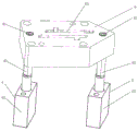
FIG. 1 is a schematic view of a lower die structure of a vehicle lower cover plate bracket forming and shearing continuous die provided by the utility model;
FIG. 2 is a schematic structural diagram of an upper die of a continuous die for forming and shearing a vehicle lower cover plate bracket, provided by the utility model;
FIG. 3 is a schematic structural diagram of a jacking mechanism of a vehicle lower cover plate bracket forming and shearing continuous die provided by the utility model;
the names and serial numbers of the parts in the figure are as follows:
1 is a lower die holder, 2 is a feeding hole, 3 is a guide pillar, 4 is a jacking mechanism, 5 is a punching female die, 6 is a punching female die II, 7 is a trimming female die, 8 is a forming female die I, 9 is a forming female die II, 10 is a punching female die III, 11 is a cutting support block, 12 is a discharging hole, 13 is an upper die holder, 14 is a hoisting block, 15 is a guide sleeve, 16 is a positioning column, 17 is a punching male die I, 18 is a punching male die II, 19 is a trimming male die, 20 is a forming male die I, 21 is a forming male die II, 22 is a punching male die III, 23 is a cutting block, and 24 is a limiting column;
41 is a positioning hole, 42 is a cylinder, and 43 is a top column;
51 is a round hole I, 61 is a strip-shaped groove, 71 is a trimming groove, 81 is a forming groove, 91 is a forming lug II, 92 is a forming lug III, and 101 is a punching supporting block;
171 is a cylindrical punch I, 181 is a strip-shaped punching block, 191 is a trimming punching block, 201 is a forming convex block I, 211 is a forming convex block IV, and 221 is a cylindrical punch II.
Detailed Description
The present invention will be described in detail with reference to the accompanying drawings and examples.
Example 1
As shown in fig. 1-3, the present invention provides a continuous molding and shearing mold for a vehicle lower cover plate bracket, which comprises an upper mold and a lower mold;
the lower die comprises a lower die base 1, a feeding hole 2, a guide pillar 3, a jacking mechanism 4, a punching female die I5, a punching female die II 6, a trimming female die 7, a forming female die I8, a forming female die II 9, a punching female die III 10, a cutting support block 11 and a discharging hole 12;
the feed inlet 2 is arranged in the middle of the left side of the lower die holder 1, and the discharge outlet 12 is arranged in the middle of the right side of the lower die holder 1; the four guide posts 3 are respectively arranged at four corners of the lower die holder 1, and the punching female die I5, the punching female die II 6, the trimming female die 7, the forming female die I8, the forming female die II 9, the punching female die III 10 and the cutting support block 11 are sequentially arranged on the top surface of the lower die holder 1 along the left and right directions of the lower die holder 1;
the plurality of jacking mechanisms 4 are arranged on the central line of the lower die holder 1 in the left-right direction along the left-right direction and respectively correspond to the punching female die I5, the punching female die II 6, the trimming female die 7, the forming female die I8, the forming female die II 9, the punching female die III 10 and the cutting support block 11, and the jacking mechanisms 4 are provided with positioning holes 41; the jacking mechanism 4 is used for jacking up the parts on the lower die;
the upper die comprises an upper die base 13, a hoisting block 14, a guide sleeve 15, a positioning column 16, a punching male die I17, a punching male die II 18, an edge shearing male die 19, a forming male die I20, a forming male die II 21, a punching male die III 22 and a cutting block 23;
four hoisting blocks 14 are arranged and are respectively arranged on the side surfaces of four corners of the upper die holder 13; four guide sleeves 15 are arranged on four corners of the bottom surface of the upper die holder 13, are arranged corresponding to the guide pillars 3 and are sleeved on the guide pillars 3; the punching male die I17, the punching male die II 18, the trimming male die 19, the forming male die I20, the forming male die II 21, the punching male die III 22 and the cutting block 23 are sequentially arranged on the bottom surface of the upper die base 13 along the left and right directions of the upper die base 13 and respectively correspond to the shapes of the punching female die I5, the punching female die II 6, the trimming female die 7, the forming female die I8, the forming female die II 9, the punching female die III 10 and the cutting supporting block 11;
the positioning columns 16 are arranged on the central line of the upper die base 13 in the left-right direction along the left-right direction and respectively correspond to the positioning holes 41;
the punching female die I5 comprises three round holes I51 which are arranged in an isosceles triangle shape, and the isosceles triangle shape is symmetrical with the center line of the lower die holder 1 in the left and right directions;
the punching male die I17 comprises three cylindrical punches I171 arranged in an isosceles triangle shape, and the positions of the three cylindrical punches are respectively corresponding to the round holes I51;
the punching female die II 6 comprises two strip-shaped grooves 61, and the strip-shaped grooves 61 are respectively arranged on two sides of the central line of the lower die holder 1 in the left-right direction;
the punching male die II 18 comprises two strip punching blocks 181, and the shapes and the positions of the strip punching blocks 181 correspond to the strip grooves 61;
the trimming female die 7 comprises two rectangular trimming grooves 71, and the trimming grooves 71 are respectively arranged on two sides of the central line of the lower die holder 1 in the left-right direction;
the trimming male die 19 comprises two rectangular trimming punching blocks 191, and the shapes and the positions of the trimming punching blocks 191 correspond to the trimming grooves 71;
the forming female die I8 comprises two rectangular forming grooves 81, the forming grooves 81 are respectively arranged on two sides of the central line of the lower die holder 1 in the left-right direction, an inclined plane is arranged on one side in each forming groove 81, and the positions of the cutting inclined planes of the two forming grooves 81 are respectively arranged on the left side and the right side;
the molding male die I20 comprises two rectangular molding bumps I201, and the shapes and the positions of the molding bumps I201 correspond to those of the molding grooves 81;
the forming female die II 9 comprises two rectangular forming convex blocks II 91 and two groups of rectangular forming convex blocks III 92, the two forming convex blocks II 91 are respectively arranged on two sides of the central line of the left and right directions of the lower die holder 1, and the adjacent side surfaces of the two forming convex blocks II 91 are contacted; the two groups of forming convex blocks III 92 are respectively arranged at the sides of the two forming convex blocks II 91, and the spaces between the forming convex blocks II 91 and the forming convex blocks III 92 jointly form a concave part of the forming female die II 9;
the forming male die II 21 comprises two L-shaped forming convex blocks IV 211, and the shapes and the positions of the two forming convex blocks IV 211 correspond to the concave parts of the forming female die II 9;
the punching female die III 10 comprises two rectangular punching supporting blocks 101, the punching supporting blocks 101 are respectively arranged on two sides of the central line of the lower die holder 1 in the left and right directions, and two round holes II 102 are formed in the upper surfaces of the punching supporting blocks 101;
the punching male die III 22 comprises four cylindrical punch heads II 221, and the positions of the cylindrical punch heads II 221 correspond to the round holes II 102 respectively;
the jacking mechanism 4 comprises an air cylinder 42 and a jacking column 43, the air cylinder 42 is arranged at the bottom of the lower die holder 1, the jacking column 43 is connected with a piston rod of the air cylinder 42, the jacking column 43 penetrates through the lower die holder 1 and then vertically extends upwards, and the positioning hole 41 is arranged at the top of the jacking column 43;
the die further comprises a plurality of groups of limiting columns 24, wherein the groups of limiting columns 24 are respectively arranged on the front side and the rear side of the lower die holder 1 and the upper die holder 13 along the left-right direction; two limiting columns 24 are arranged in each group and are respectively arranged at the corresponding positions of the top surface of the lower die holder 1 and the bottom surface of the upper die holder 13.
Claims (9)
1. The utility model provides a continuous mould is cuted in shaping of vehicle lower cover plate support, includes mould and lower mould, its characterized in that:
the lower die comprises a lower die base (1), a feeding hole (2), a guide pillar (3), a jacking mechanism (4), a punching female die I (5), a punching female die II (6), a trimming female die (7), a forming female die I (8), a forming female die II (9), a punching female die III (10), a cutting support block (11) and a discharging hole (12);
the feed inlet (2) is arranged in the middle of the left side of the lower die base (1), and the discharge outlet (12) is arranged in the middle of the right side of the lower die base (1); the four guide posts (3) are respectively arranged at four corners of the lower die holder (1), and the punching female die I (5), the punching female die II (6), the trimming female die (7), the forming female die I (8), the forming female die II (9), the punching female die III (10) and the cutting support block (11) are sequentially arranged on the top surface of the lower die holder (1) along the left and right directions of the lower die holder (1);
the jacking mechanisms (4) are arranged on the central line of the lower die holder (1) in the left-right direction along the left-right direction and respectively correspond to the punching female die I (5), the punching female die II (6), the trimming female die (7), the forming female die I (8), the forming female die II (9), the punching female die III (10) and the cutting support block (11), and the jacking mechanisms (4) are provided with positioning holes (41); the jacking mechanism (4) is used for jacking up the parts on the lower die;
the upper die comprises an upper die base (13), a hoisting block (14), a guide sleeve (15), a positioning column (16), a punching male die I (17), a punching male die II (18), an edge shearing male die (19), a forming male die I (20), a forming male die II (21), a punching male die III (22) and a cutting block (23);
four hoisting blocks (14) are arranged and are respectively arranged on the side surfaces of four corners of the upper die holder (13); four guide sleeves (15) are arranged on four corners of the bottom surface of the upper die holder (13), are arranged corresponding to the guide posts (3) and are sleeved on the guide posts (3); the punching male die I (17), the punching male die II (18), the trimming male die (19), the forming male die I (20), the forming male die II (21), the punching male die III (22) and the cutting block (23) are sequentially arranged on the bottom surface of the upper die base (13) along the left and right directions of the upper die base (13) and respectively correspond to the shapes of the punching female die I (5), the punching female die II (6), the trimming female die (7), the forming female die I (8), the forming female die II (9), the punching female die III (10) and the cutting supporting block (11);
the positioning columns (16) are arranged on the central line of the upper die base (13) in the left-right direction along the left-right direction and respectively correspond to the positioning holes (41).
2. The vehicle lower deck support form-shear continuum die of claim 1, further comprising:
the punching female die I (5) comprises three circular holes I (51) which are arranged in an isosceles triangle shape, and the isosceles triangle shape is symmetrical with the central line of the lower die holder (1) in the left and right directions;
the punching male die I (17) comprises three cylindrical punches I (171) which are arranged in an isosceles triangle shape, and the positions of the three cylindrical punches I (171) correspond to the positions of the round holes I (51).
3. The vehicle lower deck support form-shear continuum die of claim 1, further comprising:
the punching female die II (6) comprises two strip-shaped grooves (61), and the strip-shaped grooves (61) are respectively arranged on two sides of the central line of the lower die holder (1) in the left and right directions;
the punching male die II (18) comprises two strip punching blocks (181), and the shapes and the positions of the strip punching blocks (181) correspond to those of the strip grooves (61).
4. The vehicle lower deck support form-shear continuum die of claim 1, further comprising:
the trimming female die (7) comprises two rectangular trimming grooves (71), and the trimming grooves (71) are respectively arranged on two sides of the central line of the lower die holder (1) in the left-right direction;
the trimming male die (19) comprises two rectangular trimming punching blocks (191), and the shapes and the positions of the trimming punching blocks (191) correspond to the trimming grooves (71).
5. The vehicle lower deck support form-shear continuum die of claim 1, further comprising:
the forming female die I (8) comprises two rectangular forming grooves (81), the forming grooves (81) are respectively arranged on two sides of the central line of the lower die holder (1) in the left-right direction, an inclined plane is arranged on one side in each forming groove (81), and the positions of the cut inclined planes of the two forming grooves (81) are respectively arranged on the left side and the right side;
the forming male die I (20) comprises two rectangular forming lugs I (201), and the shapes and the positions of the forming lugs I (201) correspond to those of the forming grooves (81).
6. The vehicle lower deck support form-shear continuum die of claim 1, further comprising:
the forming female die II (9) comprises two rectangular forming convex blocks II (91) and two groups of rectangular forming convex blocks III (92), the two forming convex blocks II (91) are respectively arranged on two sides of the central line in the left-right direction of the lower die holder (1), and the adjacent side surfaces of the two forming convex blocks II (91) are in contact; two groups of forming convex blocks III (92) are respectively arranged at the sides of the two forming convex blocks II (91), and the spaces between the forming convex blocks II (91) and the forming convex blocks III (92) jointly form a concave part of a forming female die II (9);
the forming male die II (21) comprises two L-shaped forming convex blocks IV (211), and the shapes and the positions of the two forming convex blocks IV (211) correspond to the concave parts of the forming female die II (9).
7. The vehicle lower deck support form-shear continuum die of claim 1, further comprising:
the punching female die III (10) comprises two rectangular punching supporting blocks (101), the punching supporting blocks (101) are respectively arranged on two sides of the central line of the left and right directions of the lower die holder (1), and two round holes II (102) are formed in the upper surfaces of the punching supporting blocks (101);
the punching male die III (22) comprises four cylindrical punch heads II (221), and the positions of the cylindrical punch heads II (221) correspond to the positions of the round holes II (102) respectively.
8. The vehicle lower deck support form-shear continuum die of claim 1, further comprising:
climbing mechanism (4) include cylinder (42), fore-set (43), cylinder (42) locate the bottom of die holder (1), fore-set (43) be connected with the piston rod of cylinder (42), fore-set (43) pass vertical upwards extension behind die holder (1), locating hole (41) locate fore-set (43) top.
9. The vehicle lower deck support form-shear continuum die of claim 1, further comprising:
the die also comprises a plurality of groups of limiting columns (24), wherein the groups of limiting columns (24) are respectively arranged on the front side and the rear side of the lower die holder (1) and the upper die holder (13) along the left-right direction; two limiting columns (24) are arranged in each group and are respectively arranged at the corresponding positions of the top surface of the lower die base (1) and the bottom surface of the upper die base (13).
Priority Applications (1)
| Application Number | Priority Date | Filing Date | Title |
|---|---|---|---|
| CN202021913361.2U CN215544202U (en) | 2020-09-04 | 2020-09-04 | Continuous mould is cuted in shaping of vehicle lower cover plate support |
Applications Claiming Priority (1)
| Application Number | Priority Date | Filing Date | Title |
|---|---|---|---|
| CN202021913361.2U CN215544202U (en) | 2020-09-04 | 2020-09-04 | Continuous mould is cuted in shaping of vehicle lower cover plate support |
Publications (1)
| Publication Number | Publication Date |
|---|---|
| CN215544202U true CN215544202U (en) | 2022-01-18 |
Family
ID=79814589
Family Applications (1)
| Application Number | Title | Priority Date | Filing Date |
|---|---|---|---|
| CN202021913361.2U Active CN215544202U (en) | 2020-09-04 | 2020-09-04 | Continuous mould is cuted in shaping of vehicle lower cover plate support |
Country Status (1)
| Country | Link |
|---|---|
| CN (1) | CN215544202U (en) |
-
2020
- 2020-09-04 CN CN202021913361.2U patent/CN215544202U/en active Active
Similar Documents
| Publication | Publication Date | Title |
|---|---|---|
| CN105149440A (en) | Machining die set for booster rear shell based on magnesium-aluminum alloy | |
| CN102672046A (en) | Die for automatically punching, forming and assembling radiating fin of light-emitting diode (LED) lamp | |
| CN215544202U (en) | Continuous mould is cuted in shaping of vehicle lower cover plate support | |
| CN209998187U (en) | stamping continuous die combining multiple processes | |
| CN216632265U (en) | Automatic mould for movable bottom plate of cast iron wheel | |
| CN214601461U (en) | Metal product processing stamping platform | |
| CN214184887U (en) | Multi-process continuous die for mounting bracket of lower cover plate of vehicle | |
| CN203695751U (en) | Composite die for stamping and edge cutting of U-shaped automobile control arm forge piece | |
| CN206286418U (en) | Earpiece molding assembly, mould and former | |
| CN112808858B (en) | Progressive die for manufacturing spring arms | |
| CN213944549U (en) | Turn-ups plastic mould of automobile wheel cover spare left and right sides common mode | |
| CN205309094U (en) | Whole stamping forming cold -working mould of trapezoidal gauge apron | |
| CN211360323U (en) | Trimming and punching forming die | |
| CN204123471U (en) | Conducting resinl Progressive Dies | |
| CN213671408U (en) | Continuous die for outer plate reinforcing plate of rear side door of vehicle | |
| CN211437740U (en) | Square gasket mold processing | |
| CN213559487U (en) | Vehicle side door C post inner panel drawing die | |
| CN216175880U (en) | Lamp holder blanking connection punching die | |
| CN213671407U (en) | Continuous die for outer plate and windowsill reinforcing plate of front side door of vehicle | |
| CN218963808U (en) | High-precision, convenient and efficient safe pole stamping die structure | |
| CN217748936U (en) | Assembling die is used in automobile parts processing | |
| CN214053355U (en) | Trimming and punching composite die for automobile floor piece | |
| CN216937796U (en) | Large-scale thin wall spare shaping device | |
| CN216262996U (en) | Blanking and punching die for film seat of electric switch valve | |
| CN213559454U (en) | Continuous die for upper plate of energy absorption box of vehicle anti-collision cross beam |
Legal Events
| Date | Code | Title | Description |
|---|---|---|---|
| GR01 | Patent grant | ||
| GR01 | Patent grant |