CN215467477U - Motor housing stamping device - Google Patents
Motor housing stamping device Download PDFInfo
- Publication number
- CN215467477U CN215467477U CN202121147787.6U CN202121147787U CN215467477U CN 215467477 U CN215467477 U CN 215467477U CN 202121147787 U CN202121147787 U CN 202121147787U CN 215467477 U CN215467477 U CN 215467477U
- Authority
- CN
- China
- Prior art keywords
- stamping
- plate
- upper die
- bottom plate
- disposed
- Prior art date
- Legal status (The legal status is an assumption and is not a legal conclusion. Google has not performed a legal analysis and makes no representation as to the accuracy of the status listed.)
- Active
Links
Images


Landscapes
- Presses And Accessory Devices Thereof (AREA)
Abstract
The utility model discloses a motor shell stamping device, which is characterized in that: the stamping device comprises a bottom plate, wherein a lower die mechanism is vertically arranged in the middle of the bottom plate in a sliding manner, bottom stamping mechanisms are respectively arranged at the left end and the right end of the upper surface of the bottom plate in a centering manner, a stamping driving mechanism is arranged behind the upper surface of the bottom plate and is respectively in sliding butt joint with the two bottom stamping mechanisms, a top plate is arranged above the bottom plate in parallel, the bottom plate and the top plate are fixedly connected through a support column, a material channel is horizontally arranged on the upper surface of the top plate, an upper die mechanism is arranged on the material channel and vertically corresponds to the lower die mechanism, the upper die mechanism is respectively vertically penetrated through and is in sliding connection with the material channel and the top plate, a material ejecting mechanism is arranged on the upper surface of the top plate in front of the upper die mechanism, and the material ejecting mechanism is in sliding connection with the material channel; the stamping machine has the advantages of simple structure, convenience in use, automation realization, labor saving, capability of completing the stamping of the top and the bottom of the motor shell at one time, improvement on production efficiency and good market application value.
Description
Technical Field
The utility model relates to the technical field of stamping equipment, in particular to a motor shell stamping device.
Background
Motor housing is the important component of motor, nevertheless need use stamping device during motor housing machine-shaping, the stamping device who is used for motor housing processing nevertheless all places motor housing in stamping device's bottom and carries out the punching press, and the in-process motor housing of punching press easily takes place the skew, and then influences motor housing processingquality to top and the bottom punching press to the shell can not once be accomplished, consequently, prior art has the defect, needs the improvement.
SUMMERY OF THE UTILITY MODEL
Aiming at the defects in the prior art, the utility model aims to provide a motor shell stamping device to solve the problems in the background technology, and the utility model adopts the following technical scheme for realizing the aim: the motor shell stamping device comprises a bottom plate, wherein a lower die mechanism is vertically arranged in the middle of the bottom plate in a sliding mode, bottom stamping mechanisms are respectively arranged at the left end and the right end of the upper surface of the bottom plate in a centering mode, a stamping driving mechanism is arranged behind the upper surface of the bottom plate and is respectively in sliding butt joint with the two bottom stamping mechanisms, a top plate is arranged above the bottom plate in parallel, the bottom plate and the top plate are fixedly connected through supporting columns, a material channel is horizontally arranged on the upper surface of the top plate, an upper die mechanism is arranged on the material channel and vertically corresponds to the lower die mechanism, the upper die mechanism vertically penetrates through and is in sliding connection with the material channel and the top plate, an ejection mechanism is arranged on the upper surface of the top plate in front of the upper die mechanism and is in sliding connection with the material channel, and the lower die mechanism comprises a base, the base sets up bottom plate upper surface middle part, be provided with the die holder in the base, the preceding terminal surface of bottom plate is provided with first mounting panel perpendicularly, the bottom level of first mounting panel is provided with ejecting cylinder mounting panel, be provided with ejecting cylinder perpendicularly on the ejecting cylinder mounting panel, the ejector pin fixed plate is installed to ejecting cylinder's work end, ejector pin fixed plate upper surface is provided with many ejector pins, many the ejector pin runs through respectively and sliding connection the bottom plate with the die holder.
Preferably, the upper die mechanism comprises a mounting seat, the mounting seat is arranged on the upper surface of the material channel, a stamping sleeve is vertically and slidably arranged in the mounting seat, a stamping connecting plate is horizontally arranged at the top of the stamping sleeve, an upper die rod is vertically and slidably arranged in the stamping sleeve, an upper die base is horizontally arranged at the bottom of the upper die rod, ejector rods are respectively and vertically arranged at the left side and the right side of the bottom of the stamping sleeve, the two ejector rods penetrate through and are slidably connected with the upper die base, supporting rods are oppositely arranged at the front side and the rear side of the top of the upper die base, the supporting rods are slidably connected with the stamping sleeve, a spring is vertically arranged at the top end of each supporting rod, an upper die cylinder supporting frame is arranged on the upper surface of the mounting seat, an upper die cylinder is vertically arranged at the top end of the upper die cylinder supporting frame, and the working end of the upper die cylinder penetrates through and is slidably connected with the stamping connecting plate, the bottom end of the upper die rod is connected with the top end of the upper die rod.
Preferably, bottom punching press mechanism includes the slide, the inside horizontal slip of slide is provided with the sliding block, the inboard one end level of sliding block is provided with the depression bar, sliding block outside one end is provided with spacing seat perpendicularly, slide outside one end level is provided with the spring groove, the spring inslot level is provided with the second spring, second spring outside one end with spacing seat butt.
Preferably, liftout mechanism includes the guide rail, the guide rail sets up roof upper surface front end, and with the material is said and is said that the leading flank is perpendicular, the slip is provided with the liftout piece on the guide rail, the liftout piece with sliding connection is said to the material, the guide rail front end be provided with liftout cylinder mounting panel on the roof perpendicularly, the level is provided with the liftout cylinder on the liftout cylinder mounting panel, the work end of liftout cylinder is connected the front end of liftout piece.
Preferably, the stamping driving mechanism comprises a stamping seat, the stamping seat is elastically connected with the upper surface of the bottom plate through a guide pillar and a guide sleeve, stamping blocks are respectively arranged at the left end and the right end of the lower surface of the stamping seat, the two stamping blocks are respectively in sliding butt joint with one end of the outer side of the corresponding sliding block, a vertical plate is vertically arranged at the front end of the upper surface of the stamping seat, and a pressing plate is horizontally arranged above the stamping connecting plate corresponding to the front end surface of the vertical plate.
Preferably, the left side and the right side of the lower die base are respectively and horizontally provided with stamping holes, and the two stamping holes are respectively in sliding connection with the corresponding stamping rods.
Preferably, the upper surface of the material pushing block is provided with a limiting block, and the limiting block is spirally connected with a limiting screw.
Preferably, the outer end of the sliding block and the inner end of the stamping block are respectively and oppositely provided with an inclined surface, and the two inclined surfaces are in sliding butt joint.
Preferably, a guide rod is arranged between the lower surface of the stamping seat and the upper surface of the bottom plate, and a third spring is sleeved on the guide rod.
Compared with the prior art, the stamping machine has the advantages that by adopting the scheme, the stamping machine is simple in structure, convenient to use, automatic, labor-saving, capable of stamping the top and the bottom of the motor shell at one time, capable of improving production efficiency and good in market application value.
Drawings
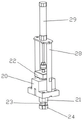
FIG. 1 is a schematic view of the overall assembly structure of one embodiment of the present invention;
FIG. 2 is a schematic view of the lower die mechanism of the embodiment of FIG. 1 of the present invention;
FIG. 3 is a schematic structural view of an upper die mechanism of the embodiment of FIG. 1 according to the present invention;
FIG. 4 is a schematic view of a portion of the upper mold mechanism of the embodiment of FIG. 1 in accordance with the present invention;
FIG. 5 is a schematic structural view of a bottom punch mechanism of the embodiment of FIG. 1 of the present invention;
FIG. 6 is a schematic structural diagram of the ejector mechanism of the embodiment of FIG. 1 according to the present invention;
FIG. 7 is a schematic diagram of the punch drive mechanism of the embodiment of FIG. 1 according to the present invention;
the figures above show: the stamping device comprises a bottom plate 1, a lower die mechanism 2, a bottom stamping mechanism 3, a stamping driving mechanism 4, a top plate 5, a material channel 6, an upper die mechanism 7, an ejection mechanism 8, a base 10, a lower die holder 11, a first mounting plate 12, an ejection cylinder mounting plate 13, an ejection cylinder 14, an ejection rod fixing plate 15, an ejection rod 16, a mounting seat 20, a stamping sleeve 21, a stamping connecting plate 22, an upper die rod 23, an upper die holder 24, an ejection rod 25, a support rod 26, an upper die cylinder support frame 28, an upper die cylinder 29, a slide seat 30, a sliding block 31, a stamping rod 32, a limit seat 33, a second spring 35, a guide rail 40, an ejection block 41, an ejection cylinder mounting plate 42, an ejection cylinder 43, a stamping seat 50, a guide pillar guide sleeve 51, a stamping block 52, a vertical plate 53, a pressing plate 54, a stamping hole 60, a limit block 61, a limit screw 62, a guide rod 64 and a third spring 65.
Detailed Description
In order to facilitate an understanding of the utility model, the utility model is described in more detail below with reference to the accompanying drawings and specific examples. Preferred embodiments of the present invention are shown in the drawings. This invention may, however, be embodied in many different forms and should not be construed as limited to the embodiments set forth herein. Rather, these embodiments are provided so that this disclosure will be thorough and complete.
It will be understood that when an element is referred to as being "secured to" another element, it can be directly on the other element or intervening elements may also be present. When an element is referred to as being "connected" to another element, it can be directly connected to the other element or intervening elements may also be present. The terms "vertical," "horizontal," "left," "right," "front," "rear," and the like as used herein are for descriptive purposes only.
Unless defined otherwise, all technical and scientific terms used herein have the same meaning as commonly understood by one of ordinary skill in the art to which this invention belongs. The terminology used in the description of the utility model herein is for the purpose of describing particular embodiments only and is not intended to be limiting of the utility model.
As shown in fig. 1 to 7, an embodiment of the present invention is a motor housing stamping device, which includes a bottom plate 1, a lower die mechanism 2 vertically slidably disposed in the middle of the bottom plate 1, bottom stamping mechanisms 3 respectively centrally disposed at the left and right ends of the upper surface of the bottom plate 1, a stamping driving mechanism 4 disposed behind the upper surface of the bottom plate 1, the stamping driving mechanism 4 respectively slidably abutted against the two bottom stamping mechanisms 3, a top plate 5 disposed above the bottom plate 1 in parallel, the bottom plate 1 and the top plate 5 fixedly connected by a supporting column 6, a material channel 6 horizontally disposed on the upper surface of the top plate 5, an upper die mechanism 7 disposed on the material channel 6, the upper die mechanism 7 and the lower die mechanism 2 vertically corresponding to each other, the upper die mechanism 7 respectively vertically penetrating and slidably connecting the material channel 6 and the top plate 5, a material ejecting mechanism 8 disposed on the upper surface of the top plate 5 in front of the upper die mechanism 7, the ejection mechanism 8 with 6 sliding connection are said to the material, lower die mechanism 2 includes base 10, base 10 sets up bottom plate 5 upper surface middle part, be provided with die holder 11 in the base 10, the preceding terminal surface of bottom plate 1 is provided with first mounting panel 12 perpendicularly, the bottom level of first mounting panel 12 is provided with ejecting cylinder mounting panel 13, be provided with ejecting cylinder 14 perpendicularly on ejecting cylinder mounting panel 13, ejector pin fixed plate 15 is installed to ejecting cylinder 14's work end, ejector pin fixed plate 15 upper surface is provided with many ejector pins 16, many ejector pin 16 runs through respectively and sliding connection bottom plate 1 with die holder 11.
Preferably, the upper die mechanism 7 includes a mounting base 20, the mounting base 20 is disposed on the upper surface of the material channel 6, a stamping sleeve 21 is vertically slidably disposed in the mounting base 20, a stamping connecting plate 22 is horizontally disposed at the top of the stamping sleeve 21, an upper die rod 23 is vertically slidably disposed in the stamping sleeve 21, an upper die base 24 is horizontally disposed at the bottom of the upper die rod 23, ejector rods 25 are respectively vertically disposed on the left and right sides of the bottom end of the stamping sleeve 21, the two ejector rods 25 penetrate through and are slidably connected with the upper die base 24, support rods 26 are oppositely disposed on the front and rear sides of the top of the upper die base 24, the support rods 26 are slidably connected with the stamping sleeve 21, a spring is vertically disposed at the top end of the support rods 26, an upper die cylinder support frame 28 is disposed on the upper surface of the mounting base 20, an upper die cylinder 29 is vertically disposed at the top end of the upper die cylinder support frame 28, the working end of the upper die cylinder 29 penetrates through and is connected with the punching connecting plate 22 in a sliding mode, and the bottom end of the upper die cylinder is connected with the top end of the upper die rod 23.
Preferably, bottom punching press mechanism 3 includes slide 30, the inside horizontal slip of slide 30 is provided with sliding block 31, the inboard one end level of sliding block 31 is provided with stamping rod 32, sliding block 31 outside one end is provided with spacing seat 33 perpendicularly, slide 30 outside one end level is provided with the spring groove, the spring inslot level is provided with second spring 35, second spring 35 outside one end with spacing seat 33 butt.
Preferably, liftout mechanism 8 includes guide rail 40, guide rail 40 sets up roof 5 upper surface front end, and with the material is said and is said that 6 leading flank is perpendicular, the last slip of guide rail 40 is provided with liftout piece 41, liftout piece 41 with 6 sliding connection are said to the material, guide rail 40 front end be provided with liftout cylinder mounting panel 42 on roof 5 perpendicularly, liftout cylinder mounting panel 42 is improved level and is provided with liftout cylinder 43, the operating end of liftout cylinder 43 is connected the front end of liftout piece 41.
Preferably, the punching driving mechanism 4 includes a punching seat 50, the punching seat 50 is elastically connected to the upper surface of the bottom plate 1 through a guide post guide sleeve 51, the left and right ends of the lower surface of the punching seat 50 are respectively provided with a punching block 52, the two punching blocks 52 are respectively in sliding abutment with one end of the outer side of the corresponding sliding block 31, the front end of the upper surface of the punching seat 50 is vertically provided with a vertical plate 53, and the front end surface of the vertical plate 53 is horizontally provided with a pressing plate 54 above the corresponding punching connecting plate 22.
Preferably, the left side and the right side of the lower die base 11 are respectively horizontally provided with a stamping hole 60, and the two stamping holes 60 are respectively connected with the corresponding stamping rods 32 in a sliding manner.
Preferably, the upper surface of the ejector block 41 is provided with a limiting block 61, and a limiting screw 62 is spirally connected to the limiting block 61.
Preferably, an outer end of the sliding block 31 and an inner end of the stamping block 52 are respectively provided with an inclined surface, and the two inclined surfaces are in sliding contact with each other.
Preferably, a guide rod 64 is arranged between the lower surface of the stamping seat 50 and the upper surface of the bottom plate 1, and a third spring 65 is sleeved on the guide rod 64.
The working principle is as follows: when the motor shell moves to the front of the ejecting mechanism through the material channel, an ejecting cylinder of the ejecting mechanism pushes an ejecting block to eject the motor shell in the material channel, an upper die cylinder of the upper die mechanism pushes an upper die rod to move downwards to abut against the top of the motor shell and is sleeved on a lower die seat of the lower die mechanism, a punching machine pushes a punching seat downwards, the punching seat pushes punching blocks on two sides to move downwards, the two punching blocks respectively push two sliding blocks to move in a centering way, the two sliding blocks respectively push corresponding punching rods to move in a centering way to punch a groove at the bottom of the motor shell, when the punching seat moves downwards, a pressing plate is driven to move downwards, the pressing plate pushes a punching sleeve to move downwards, an ejector rod at the bottom of the punching sleeve penetrates through an upper die seat to punch the top of the motor shell, the punching is completed, the punching seat is reset through a guide shaft guide sleeve and a third spring, and the punching sleeve of the upper die mechanism is reset through the spring at the top of the supporting rod, the bottom punching mechanism is reset through a second spring, and the ejection cylinder pushes the ejector rods to move upwards through the ejector rod fixing plate, so that the motor shell is ejected to the inside of the material returning channel.
The technical features mentioned above are combined with each other to form various embodiments which are not listed above, and all of them are regarded as the scope of the present invention described in the specification; also, modifications and variations may be suggested to those skilled in the art in light of the above teachings, and it is intended to cover all such modifications and variations as fall within the true spirit and scope of the utility model as defined by the appended claims.
Claims (10)
1. A motor shell stamping device is characterized by comprising a bottom plate, a lower die mechanism is vertically arranged in the middle of the bottom plate in a sliding mode, the left end and the right end of the upper surface of the bottom plate are respectively provided with a bottom punching mechanism in a centering way, the rear part of the upper surface of the bottom plate is provided with a punching driving mechanism which is respectively in sliding butt joint with the two bottom punching mechanisms, a top plate is arranged above the bottom plate in parallel, the bottom plate and the top plate are fixedly connected through a support column, a material channel is horizontally arranged on the upper surface of the top plate, an upper die mechanism is arranged on the material channel, the upper die mechanism and the lower die mechanism are vertically corresponding, the upper die mechanism respectively vertically penetrates through and is connected with the material channel and the top plate in a sliding manner, and the upper surface of the top plate in front of the upper die mechanism is provided with a material ejecting mechanism, and the material ejecting mechanism is connected with the material channel in a sliding manner.
2. The motor housing stamping device according to claim 1, wherein the lower die mechanism includes a base, the base is disposed in the middle of the upper surface of the bottom plate, a lower die holder is disposed in the base, a first mounting plate is vertically disposed on the front end surface of the bottom plate, an ejection cylinder mounting plate is horizontally disposed at the bottom end of the first mounting plate, an ejection cylinder is vertically disposed on the ejection cylinder mounting plate, an ejector rod fixing plate is mounted at a working end of the ejection cylinder, a plurality of ejector rods are disposed on the upper surface of the ejector rod fixing plate, and the plurality of ejector rods respectively penetrate through and are slidably connected with the bottom plate and the lower die holder.
3. The motor housing stamping device according to claim 2, wherein the upper die mechanism comprises a mounting seat, the mounting seat is arranged on the upper surface of the material channel, a stamping sleeve is vertically and slidably arranged in the mounting seat, a stamping connecting plate is horizontally arranged on the top of the stamping sleeve, an upper die rod is vertically and slidably arranged in the stamping sleeve, an upper die base is horizontally arranged at the bottom of the upper die rod, ejector rods are vertically arranged on the left side and the right side of the bottom end of the stamping sleeve respectively, the two ejector rods penetrate through and slidably connect the upper die base, support rods are oppositely arranged on the front side and the rear side of the top of the upper die base, the support rods are slidably connected with the stamping sleeve, a spring is vertically arranged at the top end of each support rod, an upper die cylinder support frame is arranged on the upper surface of the mounting seat, and an upper die cylinder is vertically arranged at the top end of the upper die cylinder support frame, the working end of the upper die cylinder penetrates through and is connected with the stamping connecting plate in a sliding mode, and the bottom end of the upper die cylinder is connected with the top end of the upper die rod.
4. The device for stamping the motor housing as claimed in claim 3, wherein the bottom stamping mechanism comprises a sliding base, a sliding block is horizontally and slidably arranged inside the sliding base, a stamping rod is horizontally arranged at one end inside the sliding block, a limiting seat is vertically arranged at one end outside the sliding block, a spring groove is horizontally arranged at one end outside the sliding base, a second spring is horizontally arranged in the spring groove, and one end outside the second spring abuts against the limiting seat.
5. The stamping device for the motor housing as claimed in claim 4, wherein the ejecting mechanism includes a guide rail, the guide rail is disposed at the front end of the upper surface of the top plate and is perpendicular to the front side of the material channel, an ejecting block is slidably disposed on the guide rail and is slidably connected to the material channel, an ejecting cylinder mounting plate is vertically disposed on the top plate at the front end of the guide rail, an ejecting cylinder is horizontally disposed on the ejecting cylinder mounting plate, and the working end of the ejecting cylinder is connected to the front end of the ejecting block.
6. The device for stamping a motor housing according to claim 5, wherein the stamping driving mechanism includes a stamping seat, the stamping seat is elastically connected to the upper surface of the bottom plate through a guide post and a guide sleeve, stamping blocks are respectively disposed at the left and right ends of the lower surface of the stamping seat, the two stamping blocks are respectively in sliding contact with one end of the outer side of the corresponding sliding block, a vertical plate is vertically disposed at the front end of the upper surface of the stamping seat, and a pressing plate is horizontally disposed at the front end surface of the vertical plate above the corresponding stamping connecting plate.
7. The motor housing stamping device of claim 6, wherein the left and right sides of the lower die holder are respectively horizontally provided with stamping holes, and the two stamping holes are respectively slidably connected with the corresponding stamping rods.
8. The motor housing stamping device according to claim 7, wherein a limiting block is disposed on an upper surface of the ejector block, and a limiting screw is screwed on the limiting block.
9. The device as claimed in claim 8, wherein the outer end of the sliding block and the inner end of the stamping block are respectively provided with an inclined surface, and the two inclined surfaces are in sliding contact.
10. The motor housing stamping device according to claim 9, wherein a guide rod is disposed between the lower surface of the stamping seat and the upper surface of the bottom plate, and a third spring is sleeved on the guide rod.
Priority Applications (1)
| Application Number | Priority Date | Filing Date | Title |
|---|---|---|---|
| CN202121147787.6U CN215467477U (en) | 2021-05-26 | 2021-05-26 | Motor housing stamping device |
Applications Claiming Priority (1)
| Application Number | Priority Date | Filing Date | Title |
|---|---|---|---|
| CN202121147787.6U CN215467477U (en) | 2021-05-26 | 2021-05-26 | Motor housing stamping device |
Publications (1)
| Publication Number | Publication Date |
|---|---|
| CN215467477U true CN215467477U (en) | 2022-01-11 |
Family
ID=79780480
Family Applications (1)
| Application Number | Title | Priority Date | Filing Date |
|---|---|---|---|
| CN202121147787.6U Active CN215467477U (en) | 2021-05-26 | 2021-05-26 | Motor housing stamping device |
Country Status (1)
| Country | Link |
|---|---|
| CN (1) | CN215467477U (en) |
Cited By (2)
| Publication number | Priority date | Publication date | Assignee | Title |
|---|---|---|---|---|
| CN114653853A (en) * | 2022-03-31 | 2022-06-24 | 上海寅铠精密机械制造有限公司 | Transverse stamping die and stamping method of aluminum alloy frame of photovoltaic panel |
| CN115780653A (en) * | 2023-02-03 | 2023-03-14 | 新乡职业技术学院 | Stamping die for cover plate of battery pack shell |
-
2021
- 2021-05-26 CN CN202121147787.6U patent/CN215467477U/en active Active
Cited By (3)
| Publication number | Priority date | Publication date | Assignee | Title |
|---|---|---|---|---|
| CN114653853A (en) * | 2022-03-31 | 2022-06-24 | 上海寅铠精密机械制造有限公司 | Transverse stamping die and stamping method of aluminum alloy frame of photovoltaic panel |
| CN115780653A (en) * | 2023-02-03 | 2023-03-14 | 新乡职业技术学院 | Stamping die for cover plate of battery pack shell |
| CN115780653B (en) * | 2023-02-03 | 2023-04-18 | 新乡职业技术学院 | Stamping die for cover plate of battery pack shell |
Similar Documents
| Publication | Publication Date | Title |
|---|---|---|
| CN215467477U (en) | Motor housing stamping device | |
| CN103978356B (en) | Copper sheathing group enters machine | |
| CN210702046U (en) | Stable stamping die for automobile chassis | |
| CN216263021U (en) | Anti-deviation automatic ejection hardware mould | |
| CN210817255U (en) | Press riveting device for connecting rod cross arm assembly | |
| CN212652524U (en) | Stamping die convenient to dismouting stamping die head | |
| CN210497840U (en) | Screw press for processing forge piece with ejection function | |
| CN212945006U (en) | Four-way stamping die for pipe body | |
| CN210138974U (en) | Die insert assembly | |
| CN219924227U (en) | One-step forming device for semicircular arc straight-edge part | |
| CN111791505A (en) | Automobile air conditioner air outlet and production equipment and method thereof | |
| CN220049664U (en) | Punching and trimming die for automobile parts | |
| CN218136169U (en) | But pressure equipment device of anticreep mistake proofing | |
| CN220517324U (en) | New energy automobile battery circuit board mould ejection structure | |
| CN220049734U (en) | Stamping die of rack mounting bracket | |
| CN214977885U (en) | Brake shoe perforating device of brake | |
| CN220995907U (en) | High-efficient marking device of bolt | |
| CN219561161U (en) | Automatic feeding punching machine device | |
| CN220805169U (en) | Wedge type lateral punching die | |
| CN215658944U (en) | Punching and assembling device for screw gasket | |
| CN218361864U (en) | Press machine with material ejecting structure | |
| CN219520197U (en) | Punching and chamfering integrated processing die | |
| CN219113359U (en) | Crimping jig with sliding rail | |
| CN219561037U (en) | Guide pin for stamping automobile connecting piece | |
| CN214820076U (en) | Fast conversion module system |
Legal Events
| Date | Code | Title | Description |
|---|---|---|---|
| GR01 | Patent grant | ||
| GR01 | Patent grant |