CN215417841U - Zero sequence transformer core penetrating structure - Google Patents
Zero sequence transformer core penetrating structure Download PDFInfo
- Publication number
- CN215417841U CN215417841U CN202120708914.9U CN202120708914U CN215417841U CN 215417841 U CN215417841 U CN 215417841U CN 202120708914 U CN202120708914 U CN 202120708914U CN 215417841 U CN215417841 U CN 215417841U
- Authority
- CN
- China
- Prior art keywords
- zero sequence
- cavity
- sequence transformer
- connection plate
- connecting plate
- Prior art date
- Legal status (The legal status is an assumption and is not a legal conclusion. Google has not performed a legal analysis and makes no representation as to the accuracy of the status listed.)
- Active
Links
- 230000000149 penetrating effect Effects 0.000 title claims abstract description 9
- 238000000926 separation method Methods 0.000 claims abstract description 27
- 238000004080 punching Methods 0.000 claims 1
- 238000009413 insulation Methods 0.000 abstract description 21
- 230000016507 interphase Effects 0.000 abstract description 7
- 238000004804 winding Methods 0.000 abstract description 6
- 230000015556 catabolic process Effects 0.000 abstract description 5
- 238000000034 method Methods 0.000 abstract description 5
- 238000004519 manufacturing process Methods 0.000 abstract description 3
- 238000003780 insertion Methods 0.000 description 3
- 230000037431 insertion Effects 0.000 description 3
- 238000010586 diagram Methods 0.000 description 2
- 230000009286 beneficial effect Effects 0.000 description 1
- 238000001514 detection method Methods 0.000 description 1
Images

Landscapes
- Breakers (AREA)
Abstract
The utility model discloses a zero sequence transformer feed-through structure, which is characterized in that: the transformer comprises a zero sequence transformer, an A phase connection plate, an insulation plug, a B phase connection plate, a C phase connection plate, an N phase connection plate and a surrounding shell, wherein the A phase connection plate, the B phase connection plate, the C phase connection plate and the N phase connection plate penetrate through the zero sequence transformer and the surrounding shell, a separation cavity which is mutually separated and used for containing each phase connection plate is arranged inside the surrounding shell, the insulation plug is connected and matched with the surrounding shell, a containing cavity is arranged in the insulation plug, and the containing cavity is arranged on the periphery of the separation cavity and used for insulating the phase of each phase connection plate at the penetrating and collecting position. The zero sequence transformer core-penetrating interphase insulation mode is optimized, the insulation mode of winding an insulation tape is cancelled, and the risk of interphase breakdown of each connecting plate at the core-penetrating convergence position is avoided; the core penetrating process of the zero sequence transformer is simplified, and the production cost of the circuit breaker is reduced.
Description
Technical Field
The utility model relates to a zero sequence mutual inductor feed-through structure, and belongs to the field of circuit protection.
Background
The residual current operated circuit breaker is a circuit breaker used for a low-voltage distribution network, and protects circuits and equipment from being damaged by faults such as overload, short circuit and residual current, so that the safety of a power grid and the equipment is ensured.
The zero sequence transformer is used as a detection module of the residual current operated circuit breaker, and whether residual current exists in the circuit is judged by utilizing the principle of phase current vector sum balance of each phase. The current of each phase of the circuit breaker needs to pass through the zero sequence transformer, so that the electric clearance at the collection position of each connecting plate is insufficient, and the interphase breakdown is easily caused. For the above reasons, when each phase connection plate passes through the zero sequence transformer, the insulation performance between each phase connection plate must be considered.
The existing zero sequence transformer feed-through structure is usually formed by winding an insulating tape on each connecting plate, but has the following problems:
firstly, the winding of the insulating tape has certain requirements on assembly staff, and if the insulating tape is not wound in place, a user has the risk of interphase breakdown in the using process.
Secondly, the production cost of the circuit breaker is increased, and firstly, the material cost of the insulating tape is higher; and secondly, the winding of the insulating tape is time-consuming, and the process cost is relatively high.
Disclosure of Invention
The technical problem to be solved by the utility model is as follows: the insulation mode of the existing zero sequence transformer feed-through structure is high in cost and has the problem of breakdown risk in the using process.
In order to solve the above problems, the technical scheme of the present invention is to provide a zero sequence transformer feedthrough structure, which is characterized in that: the transformer comprises a zero sequence transformer, an A phase connection plate, an insulation plug, a B phase connection plate, a C phase connection plate, an N phase connection plate and a surrounding shell, wherein the A phase connection plate, the B phase connection plate, the C phase connection plate and the N phase connection plate penetrate through the zero sequence transformer and the surrounding shell, a separation cavity which is mutually separated and used for containing each phase connection plate is arranged inside the surrounding shell, the insulation plug is connected and matched with the surrounding shell, a containing cavity is arranged in the insulation plug, and the containing cavity is arranged on the periphery of the separation cavity and used for insulating the phase of each phase connection plate at the penetrating and collecting position.
Preferably, the separation cavity comprises a first separation cavity for accommodating the A-phase connecting plate, a second separation cavity for accommodating the C-phase connecting plate and a third separation cavity for accommodating the N-phase connecting plate, and the first separation cavity, the second separation cavity and the third separation cavity are separated from each other.
Preferably, an I-shaped gap is formed between the first separation cavity and the second separation cavity.
Preferably, the insulating plug is in plug connection with the surrounding shell.
Preferably, the containing cavity comprises a first containing cavity and a second containing cavity, the first containing cavity and the second containing cavity are formed by inward protruding I-shaped structures of insulating plugs, and the I-shaped structures and the I-shaped gaps are matched to insulate the connecting plates at the crossing and gathering positions.
Compared with the prior art, the utility model has the beneficial effects that:
the zero sequence transformer core-penetrating interphase insulation mode is optimized, the insulation mode of winding an insulation tape is cancelled, and the risk of interphase breakdown of each connecting plate at the core-penetrating convergence position is avoided; the core penetrating process of the zero sequence transformer is simplified, and the production cost of the circuit breaker is reduced.
Drawings
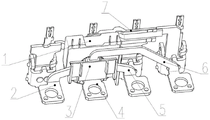
Fig. 1 is a schematic diagram of a zero sequence transformer feedthrough structure according to the present invention;
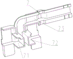
FIG. 2 is a schematic view of a wrap-around housing configuration;
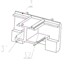
FIG. 3 is a schematic view of an insulation plug structure;
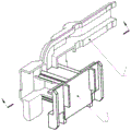
FIG. 4 is a schematic diagram of the insertion of the surrounding shell and the insulating plug;
fig. 5 is a sectional view of fig. 4 in the direction of the arrows.
Detailed Description
In order to make the utility model more comprehensible, preferred embodiments are described in detail below with reference to the accompanying drawings.
As shown in fig. 1 to 5, the zero sequence transformer feedthrough structure of the present invention includes a zero sequence transformer 1, an a-phase connection plate 2, an insulation plug 3, a B-phase connection plate 4, a C-phase connection plate 5, an N-phase connection plate 6, and a surrounding shell 7. The A-phase connecting plate 2, the B-phase connecting plate 4, the C-phase connecting plate 5 and the N-phase connecting plate 6 penetrate through the zero sequence transformer 1 and the surrounding shell 7, mutually separated separating cavities for containing the connecting plates are machined in the surrounding shell 7, each separating cavity comprises a first separating cavity 71 for containing the A-phase connecting plate 2, a second separating cavity 72 for containing the C-phase connecting plate 5 and a third separating cavity 73 for containing the N-phase connecting plate, the first separating cavity 71, the second separating cavity 72 and the third separating cavity 73 are mutually separated, and an I-shaped gap is formed between the first separating cavity 71 and the second separating cavity 72.
A containing cavity is processed in the insulating plug 3 and comprises a first containing cavity 31 and a second containing cavity 32, and the first containing cavity 31 and the second containing cavity 32 are formed by inward protruding I-shaped structures of the insulating plug 3. The insulating plug 3 is connected with the surrounding shell 7 in an inserting mode, the I-shaped structure is matched with the I-shaped gap, the first separation cavity 71 is inserted into the second containing cavity 32, the second separation cavity 72 is inserted into the first containing cavity 31, the first separation cavity and the second separation cavity form an opposite insertion structure, all the connecting plates are completely isolated, and the interphase insulation of all the connecting plates at the penetrating and collecting position is achieved.
The utility model mainly comprises the design of a surrounding shell and an insulating plug, wherein the surrounding shell and the insulating plug are in a mutual insertion structure. The surrounding shell comprises a group of separation cavities which contain and separate the connecting plates of the circuit breaker, and then an insulating plug is inserted into the surrounding shell to completely separate the connecting plates, so that the insulation of the connecting plates is realized.
The utility model cancels the insulation mode of winding the insulation tape, has simple assembly mode, and greatly reduces the core penetrating cost of the zero sequence transformer under the condition of ensuring the phase insulation performance of each connecting plate.
Claims (5)
1. The utility model provides a zero sequence transformer structure of punching which characterized in that: the connecting device comprises a zero sequence transformer (1), an A-phase connecting plate (2), an insulating plug (3), a B-phase connecting plate (4), a C-phase connecting plate (5), an N-phase connecting plate (6) and a surrounding shell (7), wherein the A-phase connecting plate (2), the B-phase connecting plate (4), the C-phase connecting plate (5) and the N-phase connecting plate (6) penetrate through the zero sequence transformer (1) and the surrounding shell (7), mutually separated separating cavities for containing the connecting plates are formed in the surrounding shell (7), the insulating plug (3) is connected and matched with the surrounding shell (7), a wrapping cavity is formed in the insulating plug (3), and the wrapping cavity is formed in the periphery of the separating cavities and used for insulating the phase of the connecting plates at the penetrating and collecting positions.
2. The zero sequence transformer feedthrough structure of claim 1, wherein: the separation cavity comprises a first separation cavity (71) used for accommodating the A-phase connecting plate (2), a second separation cavity (72) used for accommodating the C-phase connecting plate (5) and a third separation cavity (73) used for accommodating the N-phase connecting plate, and the first separation cavity (71), the second separation cavity (72) and the third separation cavity (73) are separated from each other.
3. The zero sequence transformer feedthrough structure of claim 2, wherein: an I-shaped gap is formed between the first separation cavity (71) and the second separation cavity (72).
4. The zero sequence transformer feedthrough structure of claim 1, wherein: the insulating plug (3) is connected with the surrounding shell (7) in an inserting mode.
5. The zero sequence transformer feedthrough structure of claim 1, wherein: the containing cavity comprises a first containing cavity (31) and a second containing cavity (32), the first containing cavity (31) and the second containing cavity (32) are formed by inward protruding I-shaped structures of insulating plugs (3), and the I-shaped structures and the I-shaped gaps are matched to insulate the connecting plates at the crossing and gathering positions.
Priority Applications (1)
| Application Number | Priority Date | Filing Date | Title |
|---|---|---|---|
| CN202120708914.9U CN215417841U (en) | 2021-04-07 | 2021-04-07 | Zero sequence transformer core penetrating structure |
Applications Claiming Priority (1)
| Application Number | Priority Date | Filing Date | Title |
|---|---|---|---|
| CN202120708914.9U CN215417841U (en) | 2021-04-07 | 2021-04-07 | Zero sequence transformer core penetrating structure |
Publications (1)
| Publication Number | Publication Date |
|---|---|
| CN215417841U true CN215417841U (en) | 2022-01-04 |
Family
ID=79670566
Family Applications (1)
| Application Number | Title | Priority Date | Filing Date |
|---|---|---|---|
| CN202120708914.9U Active CN215417841U (en) | 2021-04-07 | 2021-04-07 | Zero sequence transformer core penetrating structure |
Country Status (1)
| Country | Link |
|---|---|
| CN (1) | CN215417841U (en) |
Cited By (1)
| Publication number | Priority date | Publication date | Assignee | Title |
|---|---|---|---|---|
| CN119340065A (en) * | 2024-12-19 | 2025-01-21 | 浙江天正电气股份有限公司 | A zero-sequence mutual inductance structure and circuit breaker |
-
2021
- 2021-04-07 CN CN202120708914.9U patent/CN215417841U/en active Active
Cited By (1)
| Publication number | Priority date | Publication date | Assignee | Title |
|---|---|---|---|---|
| CN119340065A (en) * | 2024-12-19 | 2025-01-21 | 浙江天正电气股份有限公司 | A zero-sequence mutual inductance structure and circuit breaker |
Similar Documents
| Publication | Publication Date | Title |
|---|---|---|
| CN102082432A (en) | Cascaded converter stations and cascaded multi-terminal HVDC transmission systems | |
| CN108493634B (en) | A Grounding Device for Suppressing Electromagnetic Disturbance | |
| CN204088986U (en) | A kind of 35kV photovoltaic generation box-type substation | |
| US9312669B2 (en) | Resistor, method of assembling the same, and switchgear | |
| CN215417841U (en) | Zero sequence transformer core penetrating structure | |
| CN101651303B (en) | Gas-insulated high-capacity combined switch device with metal shell | |
| CN211905469U (en) | Three-phase three-wire high-voltage electric energy metering box of four fuses | |
| US20230290545A1 (en) | Plug mounted surge arrester | |
| CN111509701A (en) | Single bus wiring structure | |
| CN208127843U (en) | A kind of electric power tower high pressure takes electricity gas-insulated transformer substation system | |
| CN112448483A (en) | CVT energy-taking device for high-voltage alternating current limiter | |
| CN106158335A (en) | A kind of three-phase resonance-eleminating type voltage inductor | |
| CN103730246A (en) | 10KV potential transformer | |
| CN213879281U (en) | Wiring structure of synchronous combined floodgate is examined to photovoltaic power generation station line transformation group type formula | |
| CN213990152U (en) | 330kV High Voltage Shunt Reactor Compensation Station System | |
| JPS58186302A (en) | Ac/dc conversion station | |
| CN223829024U (en) | A power distribution line isolation compensation device | |
| CN206040418U (en) | Three -phase harmonic elimination formula voltage transformer | |
| CN220138085U (en) | Three-phase double-winding transformer inlet wire arrangement structure | |
| CN223296650U (en) | Current transformer for unbalanced current monitoring | |
| CN221861448U (en) | Three-phase five-column voltage transformer | |
| CN220139020U (en) | Generator control cabinet for preventing voltage transformer from being burnt out | |
| CN203813221U (en) | PT1 type power distribution station | |
| CN207650286U (en) | It stands with change high-low pressure same period line loss measuring equipment | |
| CN203813217U (en) | Improved PT1 type power distribution station |
Legal Events
| Date | Code | Title | Description |
|---|---|---|---|
| GR01 | Patent grant | ||
| GR01 | Patent grant |