CN215416632U - Support multi-functional wired wireless screen device of throwing of TYPE-C interface - Google Patents
Support multi-functional wired wireless screen device of throwing of TYPE-C interface Download PDFInfo
- Publication number
- CN215416632U CN215416632U CN202120682267.9U CN202120682267U CN215416632U CN 215416632 U CN215416632 U CN 215416632U CN 202120682267 U CN202120682267 U CN 202120682267U CN 215416632 U CN215416632 U CN 215416632U
- Authority
- CN
- China
- Prior art keywords
- circuit
- interface
- pin
- type
- screen projection
- Prior art date
- Legal status (The legal status is an assumption and is not a legal conclusion. Google has not performed a legal analysis and makes no representation as to the accuracy of the status listed.)
- Active
Links
- 238000001514 detection method Methods 0.000 claims description 10
- 230000001360 synchronised effect Effects 0.000 claims description 3
- 210000004899 c-terminal region Anatomy 0.000 claims 1
- 238000010586 diagram Methods 0.000 description 15
- 230000005540 biological transmission Effects 0.000 description 4
- 238000005070 sampling Methods 0.000 description 4
- 238000006243 chemical reaction Methods 0.000 description 2
- 230000006870 function Effects 0.000 description 2
- 230000002238 attenuated effect Effects 0.000 description 1
- 230000004888 barrier function Effects 0.000 description 1
Images


Landscapes
- Telephone Function (AREA)
Abstract
A multifunctional wired and wireless screen projection device supporting a TYPE-C interface is disclosed, a USB power supply interface is arranged at the rear end of a circuit board, a USB wired screen projection interface and a screen projection TYPE C interface are arranged at the front end of the circuit board, a wireless one-key screen projection key is designed at the center of the circuit board, the circuit board comprises a main control circuit, a dual-frequency WIFI module circuit, a quick charging circuit, a TYPE-C public seat interface circuit, a TYPE-C female seat interface circuit, a one-key screen projection key circuit, a multimedia output interface circuit and a multimedia access module circuit, the main control circuit comprises U1B, U1C, U1D and U1E, the dual-frequency WIFI module circuit comprises U2705, the quick charging circuit comprises a quick charging module U702, the TYPE-C public seat interface circuit comprises J1, the TYPE-C female seat interface circuit comprises J2, the multimedia output interface circuit comprises J2600, the multimedia access module circuit comprises a U4, and the one-touch screen key circuit comprises an SW 1100.
Description
Technical Field
The utility model relates to screen projection switching equipment, in particular to a multifunctional wired and wireless screen projection device supporting a TYPE-C interface, which is widely applied to screen projection of home theaters, meeting rooms, multimedia classrooms and the like and is also used for rapidly charging mobile phones, tablet computers and notebook computers.
Background
The conventional screen switching equipment can only carry out single wired switching and screen switching, cannot carry out wireless switching and screen switching, and cannot rapidly charge a tablet personal computer, a mobile phone and a notebook computer.
SUMMERY OF THE UTILITY MODEL
In order to solve the problems in the prior art, the utility model provides a wired and wireless screen projection device which is connected with an apple mobile phone through a lightning data line and supports wired screen projection of the apple mobile phone, supports wired screen projection of the mobile phone, a tablet personal computer and a notebook computer which are connected with type c through type c lines, projects screens of the mobile phone, the tablet personal computer and the notebook computer through an HDMI interface in a wired manner, has no delay in game playing, and can project the screens of the mobile phone, the tablet personal computer and the notebook computer onto large screens such as televisions through wireless screen projection to perform large-screen viewing.
The utility model comprises a face shell, a bottom shell and a circuit board arranged in a buckling body of the face shell and the bottom shell, wherein a multimedia HDMI (high-definition multimedia interface) is arranged at the left front end of the circuit board, an earphone interface is arranged at the left rear end of the circuit board, a USB (universal serial bus) power supply interface is arranged at the rear end of the circuit board, a USB wired screen projection interface and a mobile phone, tablet and notebook screen projection type c interface are arranged at the front end of the circuit board, and a wireless one-key screen projection key is arranged at the central position of the circuit board.
The circuit board comprises a master control circuit, a double-frequency WIFI module circuit, a quick charging circuit, a TYPE-C male seat interface circuit, a TYPE-C female seat interface circuit, a USB power supply circuit, a circuit detection protection module, a flash memory circuit, a one-key screen projection key circuit, a multimedia output interface circuit and a multimedia access module circuit, wherein the master control circuit comprises U1B, U1C, U1D, U1E, U1G, U1I and U1J, the double-frequency WIFI module circuit comprises U2705, the quick charging circuit comprises a quick charging module U702 and a voltage reduction power supply module U701, the TYPE-C male seat interface circuit comprises J1, the TYPE-C female seat interface circuit comprises J2, the USB interface circuit comprises a USB wired screen projection interface, the USB power supply circuit comprises a USB power supply interface, the circuit detection protection module comprises U703, the flash memory circuit comprises U700, the multimedia output interface circuit comprises J2600, the multimedia access module circuit comprises a U4, and the one-touch screen key circuit comprises an SW 1100.
The T3 pin of the U1B is connected with the 3 rd interface of the USB wired projection screen interface 24 through a resistor R130, the T3 and U3 pins of the U1B are connected with the 13 th and 12 th pins of the U2705, the U3 pin of the U1B is connected with the 2 nd interface of the USB wired projection screen interface 24 through a resistor R131, the R3 pin of the U1B is connected with the K5, N10, K13 and H13 pins of the U1J through a resistor R13, the R3 pin of the U1B is connected with the 1 st pin of the U702 through resistors R13, R3776 and R3751, the R3 pin of the U1B is connected with the 1 st pin of the U4 through resistors R13 and R3771, the R4 pin of the U1 4 is connected with the 2 nd pin of the U700 through resistors R13, R3776 and R3772, the R4 pin of the U1 4 is connected with the U4 through resistors R3772, the U4 and N4, the U4, the N4 pin 4 is connected with the U27072, the U1 st pin 4 through resistors R375 and N4 and the U4, m B th and J B th pins of the U1B are respectively connected with N B th pins of the U1B, U B th pins of the U1B and N B th pins of the U1B, L B th pins of the U1B are connected with 31 th pins of the U702, T B th, U B, T B, U B, P B and P B th pins of the U1B are respectively connected with 26 th, 27 th, 24 th, 25 th, 22 th, 23 th, 28, 29 th and 19 th pins of the U1B, U B, T B, R B, M B and L B, and pins of the U700 are respectively connected with 15 th, 8 th, 9 th, 1 th, 7 th and 16 th pins of the U700, 3 rd and R B of the SW1100 are respectively connected with U2705 th pins of the U1B and R B in series.
The lightning data line is connected with the apple mobile phone through the USB wired screen projection interface to support the apple mobile phone wired screen projection; connecting a mobile phone, a tablet personal computer or a notebook computer supporting a type c interface by using a type c data line to support online screen projection; the multimedia HDMI interface is connected with a projector, a television, a game machine and the like to perform wired screen projection, and no delay exists in game playing; carry out wireless screen projection under the control through dual-frenquency WIFI module U2705, throw the video of cell-phone, panel computer or notebook computer and play on big screens such as TV set, can do 2 meters, 3 meters, 5 meters, 10 meters wireless screen distances of throwing.
This device supports ordinary mode of charging, steps down through the power module U701 that steps down and exports 5V voltage and charge for the cell-phone, also supports the quick charge of notebook computer, panel computer and cell-phone, through the quick charge of module U702 giving notebook computer, panel computer and cell-phone that fills soon, both can insert with the help of the former charging wire of notebook computer, panel computer and cell-phone and insert with the wired screen interface 24 of throwing of USB and insert and charge, also can select the charging wire of other type c wantonly to insert type c interface 25 and charge, the quick charge module U702 supports 5V-9V-12V-20V input quick charge.
The J2600 is an HDMI socket, is a switching interface with equipment such as a television, a projector and the like, is an output end of an audio and video signal, is a high-performance converter from a single chip display port to an HDMI, combines a DisplayPort receiver and an HDMI transmitter, supports DisplayPort input and HDMI output by combining self-conversion functions, and the U1I is a digital multimedia chip and converts audio and video of a notebook computer, a mobile phone and a tablet computer which are accessed through a tpye c terminal into an HDMI signal to be displayed on the television.
The built-in DisplayPort receiver is completely compatible with DisplayPort 1.2a and HDCP 1.3/2.2 specifications, a 4-channel HBR2 (high bit rate 2) configuration is adopted, the built-in HDMI transmitter is a high-performance HDMI 2.0 transmitter, is completely compatible with HDMI 2.0 and HDCP 1.4/2.2 and is backwards compatible with DVI 1.0 specifications, the HDMI transmitter can support color depth of up to 36 bits (12 bits/color) and ensure reliable transmission of high-quality uncompressed video content, besides supporting various video output formats, the HDMI transmitter also supports 8-channel digital audio, the sampling rate is up to 192kHz, the sampling size is up to 24 bits, and the HBR audio, and supports HDMI 4K 60hz at most.
The voltage reduction power supply module U701 is a synchronous voltage reduction converter, and converts external high voltage into 5V to supply power to the master control during quick charging; the circuit detection protection module U703 is a high-current rectifier tube, protects the circuit from being damaged by fluctuating pulse current and voltage, and ensures the normal operation of the circuit; the U2705 is a dual-frequency WIFI module, covers two large frequency bands of 5GHz and 2.4GHz, has a transmission speed higher than that of a WIFI module other than 802.11ac, and can solve the problem of small coverage of wireless signals, although 5GHz is more attenuated than 2.4GHz and is difficult to pass through obstacles, the signals can be refracted due to the larger coverage, and the new standard can more easily enable all corners to receive the signals, the U700 is a flash memory and stores application programs of a CPU.
The utility model has the advantages that the audio and video wired or wireless screen projection of the mobile phone, the tablet personal computer and the notebook computer can be switched to the television, the projector and other similar equipment for watching, and the mobile phone, the tablet personal computer and the notebook computer can be charged quickly.
Drawings
The utility model will be further described with reference to the accompanying drawings.
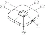
Fig. 1 is a front structural view of the present invention.
Fig. 2 is an exploded view of the structure of the present invention.
Fig. 3 is a rear view of the present invention.
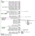
Fig. 4 is a circuit diagram of the master control module U1B according to the present invention.
Fig. 5 is a circuit diagram of the master control module U1C according to the present invention.
FIG. 6 is a circuit diagram of the master control modules U1D and U1E of the present invention.
Fig. 7 is a circuit diagram of the master control module U1F according to the present invention.
Fig. 8 is a circuit diagram of the master control module U1G according to the present invention.
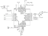
Fig. 9 is a circuit diagram of the master control module U1I according to the present invention.
Fig. 10 is a circuit diagram of the main control module U1J of the present invention.
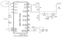
Fig. 11 is a circuit diagram of the TPYE-C male of the present invention.
FIG. 12 is a circuit diagram of the TYPE-C female connector of the present invention.
Fig. 13 is a circuit diagram of the fast charging module U702 of the present invention.
FIG. 14 is a circuit diagram of the multimedia output interface J2600 according to the present invention.
Fig. 15 is a circuit diagram of the multimedia signal access module U4 of the present invention.
Fig. 16 is a circuit diagram of the step-down power supply module U701 according to the present invention.
Fig. 17 is a circuit diagram of the circuit detection protection module U703 of the present invention.
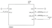
Fig. 18 is a circuit diagram of the dual-band WIFI module U2705.
Detailed Description
As shown in fig. 1 and 3, the utility model is a multifunctional wired and wireless screen projection device supporting TYPE-C interface.
As shown in fig. 2 and 3, the utility model includes a face shell 3, a bottom shell 1, and a circuit board 2 installed in a buckling body of the face shell 3 and the bottom shell 1, a multimedia HDMI interface 23 is provided at a left front end of the circuit board 2, an earphone interface 22 is provided at a left rear end of the circuit board 2, a USB power supply interface 21 is provided at a rear end of the circuit board 2, a USB wired screen projection interface 24 and a mobile phone, tablet and notebook screen projection type c interface 25 are provided at a front end of the circuit board 2, and a wireless one-key screen projection key 26 is provided at a central position of the circuit board 2.
As shown in fig. 4-18, the circuit board 2 includes a main control circuit, a dual-frequency WIFI module circuit, a fast charging circuit, a TYPE-C male seat interface circuit, a TYPE-C female seat interface circuit, a USB power supply circuit, a circuit detection protection module, a flash memory circuit, a one-key screen-projection key circuit, a multimedia output interface circuit, a multimedia access module circuit, the main control circuit includes U1B, U1C, U1D, U1E, U1G, U1I, U1J, the dual-frequency WIFI module circuit includes U2705, the fast charging circuit includes a fast charging module U702 and a voltage-reduction power supply module U701, the TYPE-C male seat interface circuit includes J1, the TYPE-C female seat interface circuit includes J2, the USB interface circuit includes a USB wired screen-projection interface 24, the USB power supply circuit includes a USB power supply interface 21, the circuit detection protection module includes U703, the flash memory circuit includes U700, the multimedia output interface circuit comprises a J2600, the multimedia access module circuit comprises a U4, and the one-touch screen key circuit comprises a SW 1100. The T3 pin of the U1B is connected with the 3 rd interface of the USB wired projection screen interface 24 through a resistor R130, the T3 and U3 pins of the U1B are connected with the 13 th and 12 th pins of the U2705, the U3 pin of the U1B is connected with the 2 nd interface of the USB wired projection screen interface 24 through a resistor R131, the R3 pin of the U1B is connected with the K5, N10, K13 and H13 pins of the U1J through a resistor R13, the R3 pin of the U1B is connected with the 1 st pin of the U702 through resistors R13, R3776 and R3751, the R3 pin of the U1B is connected with the 1 st pin of the U4 through resistors R13 and R3771, the R4 pin of the U1 4 is connected with the 2 nd pin of the U700 through resistors R13, R3776 and R3772, the R4 pin of the U1 4 is connected with the U4 through resistors R3772, the U4 and N4, the U4, the N4 pin 4 is connected with the U27072, the U1 st pin 4 through resistors R375 and N4 and the U4, m B th and J B th pins of the U1B are respectively connected with N B th pins of the U1B, U B th pins of the U1B and N B th pins of the U1B, L B th pins of the U1B are connected with 31 th pins of the U702, T B th, U B, T B, U B, P B and P B th pins of the U1B are respectively connected with 26 th, 27 th, 24 th, 25 th, 22 th, 23 th, 28, 29 th and 19 th pins of the U1B, U B, T B, R B, M B and L B, and pins of the U700 are respectively connected with 15 th, 8 th, 9 th, 1 th, 7 th and 16 th pins of the U700, 3 rd and R B of the SW1100 are respectively connected with U2705 th pins of the U1B and R B in series.
The lightning data line is connected with the apple mobile phone through the USB wired screen projection interface 24, so that wired screen projection of the apple mobile phone is supported, and plug and play are realized; the mobile phone, the tablet personal computer or the notebook computer supporting the type c interface 25 are connected by a type c data line, so that online screen projection is supported, and plug and play are realized; the multimedia HDMI 23 is connected with a projector, a television, a game machine and the like to perform wired screen projection, and no delay exists in game playing; carry out wireless screen projection under the control through dual-frenquency WIFI module U2705, throw the video of cell-phone, panel computer or notebook computer and play on big screens such as TV set, can do 2 meters, 3 meters, 5 meters, 10 meters wireless screen distances of throwing. This device supports ordinary mode of charging, steps down through the power module U701 that steps down and exports 5V voltage and charge for the cell-phone, also supports the quick charge of notebook computer, panel computer and cell-phone, through the quick charge of module U702 giving notebook computer, panel computer and cell-phone that fills soon, both can insert with the help of the former charging wire of notebook computer, panel computer and cell-phone and insert with the wired screen interface 24 of throwing of USB and insert and charge, also can select the charging wire of other type c wantonly to insert type c interface 25 and charge, the quick charge module U702 supports 5V-9V-12V-20V input quick charge. The J2600 is an HDMI socket, is a switching interface with equipment such as a television, a projector and the like, is an output end of an audio and video signal, is a high-performance converter from a single chip display port to an HDMI, combines a DisplayPort receiver and an HDMI transmitter, supports DisplayPort input and HDMI output by combining self-conversion functions, and the U1I is a digital multimedia chip and converts audio and video of a notebook computer, a mobile phone and a tablet computer which are accessed through a tpye c terminal into an HDMI signal to be displayed on the television. The built-in DisplayPort receiver is completely compatible with DisplayPort 1.2a and HDCP 1.3/2.2 specifications, a 4-channel HBR2 (high bit rate 2) configuration is adopted, the built-in HDMI transmitter is a high-performance HDMI 2.0 transmitter, is completely compatible with HDMI 2.0 and HDCP 1.4/2.2 and is backwards compatible with DVI 1.0 specifications, the HDMI transmitter can support color depth of up to 36 bits (12 bits/color) and ensure reliable transmission of high-quality uncompressed video content, besides supporting various video output formats, the HDMI transmitter also supports 8-channel digital audio, the sampling rate is up to 192kHz, the sampling size is up to 24 bits, and the HBR audio supports HDMI 4K 60hz at most. The voltage-reducing power supply module U701 is a synchronous voltage-reducing converter, and converts external high voltage into 5V to supply power to the master control during quick charging. The circuit detection protection module U703 is a high-current rectifier tube, protects the circuit from being damaged by fluctuating pulse current and voltage, and ensures the normal operation of the circuit. U2705 is dual-frenquency WIFI module, covers two broad frequency channels of 5GHz and 2.4GHz, and its transmission speed is faster than the WIFI module of non-802.11 ac, can improve the little problem of wireless signal coverage moreover, and although 5GHz is stronger than 2.4 GHz's decay, difficult barrier of passing, because coverage is bigger, the signal can produce the refraction, and new standard can make each corner can both receive the signal more easily on the contrary. The U700 is a flash memory, and stores application programs of the CPU line.
Claims (5)
1. The multifunctional wired and wireless screen projection device supporting the TYPE-C interface is characterized by comprising a face shell and a bottom shell and a circuit board arranged in the buckling body of the face shell and the bottom shell, wherein a multimedia HDMI interface is arranged at the left front end of the circuit board, an earphone interface is arranged at the left rear end of the circuit board, a USB power supply interface is arranged at the rear end of the circuit board, a USB wired screen projection interface and a screen projection TYPE C interface of a mobile phone, a tablet and a notebook are arranged at the front end of the circuit board, a wireless one-key screen projection key is arranged at the central position of the circuit board, and the circuit board comprises a main control circuit, a dual-frequency WIFI module circuit, a quick-charging circuit, a TYPE-C male seat interface circuit, a TYPE-C female seat interface circuit, a USB power supply circuit, a circuit detection and protection module, a flash memory circuit, a one-key screen projection key circuit, a multimedia output interface circuit, Multimedia access module circuit, master control circuit includes U1B, U1C, U1D, U1E, U1G, U1I, U1J, dual-frenquency WIFI module circuit includes U2705, fill the circuit soon including filling module U702 and step-down power module U701 soon, the public seat interface circuit of TYPE-C includes J1, female seat interface circuit of TYPE-C includes J2, and USB interface circuit includes that the USB is wired to throw the screen interface, USB power supply circuit includes USB power supply interface, circuit detection protection module includes U703, flash memory circuit includes U700, multimedia output interface circuit includes J2600, multimedia access module circuit includes U4, a key throws the screen button circuit and includes SW 1100.
2. The multifunctional wired and wireless screen projection device supporting a TYPE-C interface according to claim 1, wherein the T3 pin of U1B is connected with the 3 rd interface of the USB wired screen projection interface 24 through a resistor R130, the T3 and U3 pins of U1B are connected with the 13 th and 12 th pins of U2705, the U3 pin of U1 3 is connected with the 2 nd interface of the USB wired screen projection interface 24 through a resistor R131, the R3 pin of U1 3 is connected with the K3, N3, K3 and H3 pins of U1 3 through a resistor R3, R3776 and R3751 to the 1 st pin of U702, the R3 pin of U1 3 is connected with the 1 st pin of U3 through resistors R3 and R3771, the R3 of U1 3 is connected with the U3 through resistors R3772 and R3771, the R3772 of U1 3 is connected with the U3 through a resistor R372R 375, the U3772 and R3772, the U3 pin 3 is connected with the U3 through a resistor R375 and a resistor R375, a resistor R375 and a resistor R3772, a resistor R3772 and a resistor R3772 is connected with the U3 and a resistor R3772, a resistor R3772 is connected with the U3 and a U3, the Nth, K and K pins of the U1 are respectively connected with the R and R pins of the U1, the Mth and J pins of the U1 are respectively connected with the Nth pin of the U1, the U-th pin of the U1 and the Nth pin of the U1, the Lth pin of the U1 is connected with the 31 st pin of the U702, the T, U, P and pins of the U1 are respectively connected with the 26 th, 27 th, 24 th, 25 th, 22 th, 23 th, 28 th, 29 th and 19 th pins of the U1, the U, P, T, R, M, L and pins of the U700 are respectively connected with the 15 th, 8 th, 9 th, 1 th, 7 th and 16 th pins of the U700, and the 3 rd connecting pin series connection of the SW1100 is respectively connected with the R pins, the 11 th pin of the U2705 and the 2 nd pin of the U700.
3. The multifunctional wired and wireless screen projection device supporting the TYPE-C interface of claim 1, wherein a lightning data line is used for wireless screen projection under the control of the dual-frequency WIFI module U2705, and videos of a mobile phone, a tablet personal computer or a notebook computer are projected onto a large screen of a television to be played, so that wireless screen projection distances of 2 m, 3 m, 5 m and 10 m can be achieved.
4. The multifunctional wired and wireless screen projection device supporting the TYPE-C interface of claim 1, wherein the J2600 is an HDMI socket and is a switching interface with a television and a projector, and the U1 is a digital multimedia chip which converts audio and video of a notebook computer, a mobile phone and a tablet computer accessed through a tpye C terminal into HDMI signals to be displayed on the television.
5. The multifunctional wired and wireless screen projection device supporting the TYPE-C interface of claim 1, wherein the voltage-reducing power supply module U701 is a synchronous voltage-reducing converter, and converts an external high voltage into 5V to supply power to a master controller during fast charging; the circuit detection protection module U703 is a high-current rectifier tube, and the U700 is a flash memory and stores application programs of a CPU row.
Priority Applications (1)
| Application Number | Priority Date | Filing Date | Title |
|---|---|---|---|
| CN202120682267.9U CN215416632U (en) | 2021-04-02 | 2021-04-02 | Support multi-functional wired wireless screen device of throwing of TYPE-C interface |
Applications Claiming Priority (1)
| Application Number | Priority Date | Filing Date | Title |
|---|---|---|---|
| CN202120682267.9U CN215416632U (en) | 2021-04-02 | 2021-04-02 | Support multi-functional wired wireless screen device of throwing of TYPE-C interface |
Publications (1)
| Publication Number | Publication Date |
|---|---|
| CN215416632U true CN215416632U (en) | 2022-01-04 |
Family
ID=79670741
Family Applications (1)
| Application Number | Title | Priority Date | Filing Date |
|---|---|---|---|
| CN202120682267.9U Active CN215416632U (en) | 2021-04-02 | 2021-04-02 | Support multi-functional wired wireless screen device of throwing of TYPE-C interface |
Country Status (1)
| Country | Link |
|---|---|
| CN (1) | CN215416632U (en) |
-
2021
- 2021-04-02 CN CN202120682267.9U patent/CN215416632U/en active Active
Similar Documents
| Publication | Publication Date | Title |
|---|---|---|
| US9794496B2 (en) | Meeting room power and multimedia center device | |
| US8378653B2 (en) | HDMI driver tail current transistors with current mirror controlled leads | |
| CN100440947C (en) | a multifunctional television | |
| CN205376973U (en) | Multifunctional adapter | |
| CN103347162A (en) | Vehicle-mounted device and smart mobile phone interaction control system and method thereof | |
| CN215416632U (en) | Support multi-functional wired wireless screen device of throwing of TYPE-C interface | |
| CN102226879A (en) | Realization method and device for expandable intelligent base based on tablet computer | |
| CN201657180U (en) | projection computer all-in-one | |
| US20100225279A1 (en) | Portable electronic device and charging system using the same | |
| CN103337758A (en) | High definition data connection line | |
| CN101325671A (en) | Multifunctional TV set | |
| CN113259758A (en) | Driving system board and mobile phone on-screen line based on same | |
| CN207199941U (en) | A kind of signal adapter | |
| CN103686045A (en) | Audio/video information transmission method and equipment | |
| CN213783468U (en) | LED television mainboard and LED display device | |
| CN211506458U (en) | Intelligent video communication control circuit capable of realizing wireless screen projection and screen projection device | |
| CN212659071U (en) | Docking station | |
| US9841661B2 (en) | Projecting system with extendable modules | |
| CN201623272U (en) | Multifunctional connecting wire of projector | |
| CN219875871U (en) | Screen throwing device for horizontal and vertical screen display and electronic equipment | |
| CN201234317Y (en) | Multifunctional television set | |
| CN101098425A (en) | A method for displaying port or terminal state information of a video device | |
| CN112969083A (en) | Method and system for simultaneously displaying main picture and sub-picture in PIP picture in vertical screen mode | |
| CN207052913U (en) | Adjustable interface conversion device | |
| CN223582475U (en) | Interface expansion device |
Legal Events
| Date | Code | Title | Description |
|---|---|---|---|
| GR01 | Patent grant | ||
| GR01 | Patent grant |