CN215396687U - Thermal-insulated energy-conserving injection moulding device based on infrared heating - Google Patents
Thermal-insulated energy-conserving injection moulding device based on infrared heating Download PDFInfo
- Publication number
- CN215396687U CN215396687U CN202121315073.1U CN202121315073U CN215396687U CN 215396687 U CN215396687 U CN 215396687U CN 202121315073 U CN202121315073 U CN 202121315073U CN 215396687 U CN215396687 U CN 215396687U
- Authority
- CN
- China
- Prior art keywords
- fixedly connected
- heating
- wall
- cylinder
- preheating
- Prior art date
- Legal status (The legal status is an assumption and is not a legal conclusion. Google has not performed a legal analysis and makes no representation as to the accuracy of the status listed.)
- Active
Links
Images


Landscapes
- Injection Moulding Of Plastics Or The Like (AREA)
Abstract
The utility model discloses a heat-insulation energy-saving injection molding device based on infrared heating, and relates to the field of injection molding devices. According to the utility model, the annular cavity is formed in the heating cylinder, the annular heating plate and the nanometer heating pipes are arranged in the annular cavity, the annular heating plate is heated through the nanometer heating pipes, heat is transferred into the heating cylinder through the annular heating plate as far as possible to heat raw materials in the heating cylinder, air is introduced into the annular cavity through the air inlet pipe and the air pump, the air carries partial heat under the heating of the nanometer heating pipes, hot air enters the hot air channel through the air guide pipe, and then the raw materials in the preheating cylinder are preheated through the hot air channel, so that the waste of heat is avoided, the melting rate of the raw materials is increased, and the production efficiency is improved.
Description
Technical Field
The utility model relates to the field of injection molding devices, in particular to a heat-insulating energy-saving injection molding device based on infrared heating.
Background
The injection molding machine heats and melts raw materials such as plastics and the like to enable the raw materials to be injected and filled in a mold cavity, so that products with various shapes are obtained, and the injection molding machine is widely applied to the manufacturing of automobile parts. At present, raw materials are melted in a material cylinder by a commonly-used injection molding machine, the raw materials are extruded by rotating a screw rod arranged in the material cylinder, and a heating ring is arranged on the periphery of the material cylinder, so that the raw materials in the material cylinder can be heated and melted.
SUMMERY OF THE UTILITY MODEL
The utility model aims to provide a heat-insulating energy-saving injection molding device based on infrared heating, so as to solve the problems in the background technology.
In order to achieve the purpose, the utility model provides the following technical scheme: an infrared heating-based heat-insulating energy-saving injection molding device comprises a bottom plate, wherein a heating cylinder is fixedly connected to the middle of the upper surface of the bottom plate, a preheating cylinder is fixedly connected to the middle of the upper surface of the heating cylinder, an annular cavity is formed in the heating cylinder, an annular heating plate is fixedly connected to the inner wall of one side of the annular cavity, a plurality of nanometer heating pipes distributed in an annular array are fixedly connected to the inner part of the annular cavity, the outer wall of one side of each nanometer heating pipe is attached to the outer wall of the annular heating plate, a hot air channel is formed in the preheating cylinder and distributed in a spiral shape, an air guide pipe is fixedly connected to one side of the inner wall of the top end of the annular cavity, the air guide pipe extends into the preheating cylinder and is communicated with the bottom end of the hot air channel, the top end of the hot air channel is communicated with the outside, and the bottom end of the inner wall of one side of the annular cavity is fixedly connected with an air inlet pipe, the one end of intake pipe extends to the heating cylinder outside, the one end fixedly connected with air pump of intake pipe, the equal fixedly connected with radiation shield of lateral wall of heating cylinder and preheating cylinder.
Preferably, the inside of cartridge heater is provided with the pivot, the bottom inner wall swing joint of bearing and cartridge heater is passed through to the bottom of pivot, a plurality of puddlers that are the vertical distribution of equidistant of the equal fixedly connected with of both sides outer wall of cartridge heater, the bottom middle part fixedly connected with servo motor of bottom plate, servo motor's output and pivot fixed connection.
Preferably, a through groove is formed in the middle of the inner wall of the bottom end of the preheating cylinder, the through groove extends into the heating cylinder, a movable block is arranged inside the preheating cylinder, the movable block is arranged in a conical shape, the middle of the bottom end of the movable block is fixedly connected with a lug matched with the through groove, and the lug is inserted into the through groove.
Preferably, the bottom fixed surface of movable block is connected with sealed the pad, the lower surface of sealed pad and the laminating of the bottom inner wall surface of a section of thick bamboo of preheating, the top of movable block is provided with the threaded rod, the top swing joint of bearing and movable block is passed through to the bottom of threaded rod.
Preferably, the middle part of the upper surface of the preheating cylinder is provided with a thread groove matched with the threaded rod, the top end of the threaded rod penetrates through the thread groove and extends to the outer side of the top end of the preheating cylinder, and the top end part of the threaded rod is fixedly connected with a rotary cover.
Preferably, the equal fixedly connected with telescopic tube in top inner wall both sides of a section of thick bamboo of preheating, telescopic tube keeps away from the one end of preheating a section of thick bamboo top inner wall and the last fixed surface of movable block and is connected, upper surface one side fixedly connected with inlet pipe of a section of thick bamboo of preheating, the bottom of inlet pipe and the inside valve that is linked together of a section of thick bamboo of preheating, the top of a section of thick bamboo of preheating is provided with the valve.
Preferably, bottom inner wall one side fixedly connected with discharging pipe of cartridge heater, the bottom of discharging pipe extends to the bottom outside of bottom plate, the bottom fixedly connected with valve of discharging pipe, one side top fixedly connected with electron thermometer of cartridge heater, inside electron thermometer's response end extended to the annular chamber, the equal fixedly connected with support column of lower surface four corners department of bottom plate.
The utility model has the technical effects and advantages that:
1. according to the utility model, the annular cavity is formed in the heating cylinder, the annular heating plate and the nanometer heating pipes are arranged in the annular cavity, the annular heating plate is heated through the nanometer heating pipes, heat is transferred to the inside of the heating cylinder through the annular heating plate as far as possible to heat raw materials in the heating cylinder, air is introduced into the annular cavity through the air inlet pipe and the air pump, the air carries part of heat under the heating of the nanometer heating pipes, hot air enters the hot air channel through the air guide pipe, and then the raw materials in the preheating cylinder are preheated through the hot air channel, so that the waste of heat is avoided, the melting rate of the raw materials is accelerated, and the production efficiency is improved;
2. according to the utility model, the rotating shaft and the stirring rod are arranged in the heating cylinder, the rotating shaft and the stirring rod are driven to rotate through the servo motor, raw materials in the heating cylinder are stirred, so that the raw materials are uniformly heated, the production efficiency is improved, the movable block is arranged in the preheating cylinder, the threaded rod is driven to rotate through rotating the rotary cover, and the movable block is further driven to vertically move in the preheating cylinder, so that the convex block is separated from the through groove, the preheated raw materials in the preheating cylinder enter the heating cylinder through the through groove, the feeding control by workers is facilitated, the raw materials to be processed can be fully preheated in the preheating cylinder, and the practicability of the device is improved.
Drawings
Fig. 1 is a schematic cross-sectional view of the overall structure of the present invention.
Fig. 2 is an enlarged schematic view of the structure at a in fig. 1 according to the present invention.
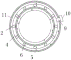
FIG. 3 is a schematic top-down view of a heater cartridge according to the present invention.
Fig. 4 is a schematic sectional view of the heating cartridge according to the present invention.
In the figure: 1. a base plate; 2. a heating cylinder; 3. a preheating cylinder; 4. an annular cavity; 5. an annular heating plate; 6. a nano heating pipe; 7. a hot gas path; 8. an air duct; 9. an air inlet pipe; 10. an air pump; 11. a heat insulating sleeve; 12. a rotating shaft; 13. a stirring rod; 14. a servo motor; 15. a through groove; 16. a movable block; 17. a bump; 18. a gasket; 19. a threaded rod; 20. a thread groove; 21. screwing a cover; 22. a telescopic sleeve; 23. a feed pipe; 24. a discharge pipe; 25. an electronic thermometer; 26. and (4) a support column.
Detailed Description
The technical solutions in the embodiments of the present invention will be clearly and completely described below with reference to the drawings in the embodiments of the present invention, and it is obvious that the described embodiments are only a part of the embodiments of the present invention, and not all of the embodiments. All other embodiments, which can be derived by a person skilled in the art from the embodiments given herein without making any creative effort, shall fall within the protection scope of the present invention.
The utility model provides an infrared heating-based heat-insulation energy-saving injection molding device which comprises a bottom plate 1, wherein a heating cylinder 2 is fixedly connected to the middle part of the upper surface of the bottom plate 1, a preheating cylinder 3 is fixedly connected to the middle part of the upper surface of the heating cylinder 2, an annular cavity 4 is formed in the heating cylinder 2, an annular heating plate 5 is fixedly connected to the inner wall of one side of the annular cavity 4, heat in the annular cavity 4 is transferred into the heating cylinder 2 through the annular heating plate 5, a plurality of nano heating pipes 6 distributed in an annular array are fixedly connected into the annular cavity 4, the outer wall of one side of each nano heating pipe 6 is attached to the outer wall of the annular heating plate 5, a large amount of heat can be generated when the nano heating pipes 6 work, most of heat is absorbed by the annular heating plate 5 and then transferred into the heating cylinder 2 to heat raw materials, and a small amount of heat is dissipated into the annular cavity 4, the preheating cylinder 3 is internally provided with a hot gas channel 7, the hot gas channel 7 is spirally distributed, the contact area of hot air and the preheating cylinder 3 is increased by the hot gas channel 7 which is spirally distributed, heat in the hot air is recycled as much as possible, one side of the inner wall of the top end of the annular cavity 4 is fixedly connected with a gas guide tube 8, the gas guide tube 8 extends into the preheating cylinder 3 and is communicated with the bottom end of the hot gas channel 7, the top end of the hot gas channel 7 is communicated with the outside, air with heat is guided into the hot gas channel 7 through the gas guide tube 8, the bottom end of the inner wall of one side of the annular cavity 4 is fixedly connected with a gas inlet tube 9, one end of the gas inlet tube 9 extends to the outside of the heating cylinder 2, one end of the gas inlet tube 9 is fixedly connected with a gas pump 10, the outside air is pumped into the annular cavity 4 through the matching of the gas inlet tube 9 and the gas pump 10, and the circulated air brings the heat dissipated inside the annular cavity 4 into the gas guide tube 8 and the hot gas channel 7, realize thermal recycle in the air, avoid thermal waste, make this device energy-concerving and environment-protective more, the equal fixedly connected with radiation shield 11 of lateral wall of cartridge heater 2 and cartridge heater 3 prevents through radiation shield 11 that the staff from touching cartridge heater 2 or cartridge heater 3 surface messenger by the mistake and being scalded, has improved the security of this device.
The interior of the heating cylinder 2 is provided with a rotating shaft 12, the bottom end of the rotating shaft 12 is movably connected with the bottom end inner wall of the heating cylinder 2 through a bearing, the outer walls of the two sides of the heating cylinder 2 are fixedly connected with a plurality of stirring rods 13 which are vertically distributed at equal intervals, the bottom end middle part of the bottom plate 1 is fixedly connected with a servo motor 14, the output end of the servo motor 14 is fixedly connected with the rotating shaft 12, the servo motor 14 drives the rotating shaft 12 and the stirring rods 13 to rotate in the heating cylinder 2, and further stirs the raw material in the heating cylinder 2, so that the raw material is uniformly heated, the heating efficiency of the raw material is improved, the middle part of the bottom end inner wall of the preheating cylinder 3 is provided with a through groove 15, the through groove 15 extends to the interior of the heating cylinder 2, the interior of the preheating cylinder 3 is provided with a movable block 16, the movable block 16 is set to be conical, the phenomenon that the raw material preheated in the interior of the preheating cylinder 3 is retained on the upper surface of the movable block 16 is avoided, the bottom end middle part of the movable block 16 is fixedly connected with a lug 17 matched with the through groove 15, the lug 17 is inserted into the through groove 15 and inserted into the through groove 15 through the lug 17, the through groove 15 is sealed, raw materials in the preheating cylinder 3 are prevented from entering the heating cylinder 2 through the through groove 15 when the raw materials in the heating cylinder 2 are heated and melted, the bottom end surface of the movable block 16 is fixedly connected with the sealing gasket 18, the lower surface of the sealing gasket 18 is attached to the bottom end inner wall surface of the preheating cylinder 3, the contact surface between the movable block 16 and the bottom end inner wall of the preheating cylinder 3 is sealed through the sealing gasket 18, partial raw materials are prevented from leaking into the heating cylinder 2, the top end of the movable block 16 is provided with the threaded rod 19, the bottom end of the threaded rod 19 is movably connected with the top end of the movable block 16 through the bearing, the threaded rod 19 drives the movable block 16 to move inside the preheating cylinder 3 when the preheating cylinder 3 moves inside, the middle part of the upper surface of the preheating cylinder 3 is provided with the threaded groove 20 matched with the threaded rod 19, the top end of the threaded rod 19 penetrates through the threaded groove 20 and extends to the outer side of the top end of the preheating cylinder 3, threaded rod 19 is at the inside vertical removal of thread groove 20 in the inside pivoted of thread groove 20, and the top end fixedly connected with spiral cover 21 of threaded rod 19 drives threaded rod 19 through rotating spiral cover 21 and rotates in thread groove 20 is inside, preheats the equal fixedly connected with telescopic tube 22 in top inner wall both sides of a section of thick bamboo 3, and telescopic tube 22 keeps away from the one end of preheating a section of thick bamboo 3 top inner wall and the last fixed surface of movable block 16 and connects telescopic tube 22 and play the guide effect to the removal of movable block 16.
A feeding pipe 23 is fixedly connected to one side of the upper surface of the preheating cylinder 3, the bottom end of the feeding pipe 23 is communicated with the interior of the preheating cylinder 3, a valve is arranged at the top end of the preheating cylinder 3, the opening and closing of the feeding pipe 23 are controlled by the valve, a worker can conveniently add raw materials into the preheating cylinder 3 through the feeding pipe 23, a discharging pipe 24 is fixedly connected to one side of the inner wall of the bottom end of the heating cylinder 2, the bottom end of the discharging pipe 24 extends to the outer side of the bottom end of the bottom plate 1, the valve is fixedly connected to the bottom end of the discharging pipe 24 and controls the opening and closing of the discharging pipe 24, the worker can conveniently discharge the heated and melted raw materials through the discharging pipe 24, an electronic thermometer 25 is fixedly connected to the top end of one side of the heating cylinder 2, a sensing end of the electronic thermometer 25 extends into the annular cavity 4, the temperature in the heating cylinder 2 is displayed through the electronic thermometer 25, and the worker can conveniently adjust the temperature in the heating cylinder 2, avoid the high or low influence machining efficiency that crosses of temperature, the equal fixedly connected with support column 26 in bottom plate 1's lower surface four corners department supports bottom plate 1 through four support columns 26.
The working principle of the utility model is as follows:
when the device is used, firstly, raw materials are added into the interior of the preheating cylinder 3 through the feeding pipe 23, the raw materials enter the interior of the heating cylinder 2 through the through groove 15, then the screw cap 21 is rotated to enable the threaded rod 19 to rotate, further the movable block 16 is driven to move downwards, the convex block 17 fixed at the bottom end of the movable block 16 is inserted into the through groove 15, the through groove 15 is sealed, the raw materials are added into the interior of the preheating cylinder 3 through the feeding pipe 23 again, then the annular heating plate 5 is heated through the plurality of nanometer heating pipes 6, the annular heating plate 5 absorbs a large amount of heat and then transmits the heat into the interior of the heating cylinder 2, the raw materials in the interior of the heating cylinder 2 are heated, then the servo motor 14 is started, the rotating shaft 12 and the stirring rod 13 are driven to rotate in the interior of the heating cylinder 2 through the servo motor 14, the raw materials in the interior of the heating cylinder 2 are stirred, the raw materials are heated evenly, the melting efficiency of the raw materials is improved, and simultaneously, through intake pipe 9 and air pump 10 to the inside air that lets in of annular chamber 4, the air possesses a large amount of heats behind the heat that receives nanometer heating pipe 6 to give out in annular chamber 4 inside, the inside hot air of annular chamber 4 enters into the inside hot gas path 7 of seting up of preheating cylinder 3 inside through air duct 8 inside, hot air passes through hot gas path 7, heat in the messenger hot air preheats the inside raw materials of preheating cylinder 3 after being absorbed by preheating cylinder 3, discharge through discharging pipe 24 after 2 inside raw materials processing of heating cylinder are accomplished, rotate spiral cover 21 simultaneously, make lug 17 and logical groove 15 separate, leading-in to heating cylinder 2 inside with the raw materials that preheat, the rate of melting of raw materials has been accelerated, and then production efficiency has been improved.
Finally, it should be noted that: although the present invention has been described in detail with reference to the foregoing embodiments, it will be apparent to those skilled in the art that modifications may be made to the embodiments or portions thereof without departing from the spirit and scope of the utility model.
Claims (7)
1. The utility model provides a thermal-insulated energy-conserving injection moulding device based on infrared heating, includes bottom plate (1), its characterized in that: the heating device is characterized in that a heating cylinder (2) is fixedly connected to the middle of the upper surface of the base plate (1), a preheating cylinder (3) is fixedly connected to the middle of the upper surface of the heating cylinder (2), an annular chamber (4) is formed inside the heating cylinder (2), an annular heating plate (5) is fixedly connected to the inner wall of one side of the annular chamber (4), a plurality of nanometer heating pipes (6) distributed in an annular array are fixedly connected to the inside of the annular chamber (4), the outer wall of one side of each nanometer heating pipe (6) is attached to the outer wall of the annular heating plate (5), a hot air channel (7) is formed inside the preheating cylinder (3), the hot air channel (7) is distributed in a spiral shape, an air guide pipe (8) is fixedly connected to one side of the inner wall of the top end of the annular chamber (4), and the air guide pipe (8) extends into the preheating cylinder (3) and is communicated with the bottom end of the hot air channel (7), the top and the outside of hot gas duct (7) are linked together, one side inner wall bottom fixedly connected with intake pipe (9) of annular chamber (4), the one end of intake pipe (9) extends to the cartridge heater (2) outside, the one end fixedly connected with air pump (10) of intake pipe (9), the equal fixedly connected with heat insulating sleeve (11) of lateral wall of cartridge heater (2) and cartridge heater (3).
2. The infrared heating-based heat-insulating energy-saving injection molding device as claimed in claim 1, wherein: the inside of cartridge heater (2) is provided with pivot (12), the bottom inner wall swing joint of bearing and cartridge heater (2) is passed through to the bottom of pivot (12), a plurality of puddlers (13) that are equidistant vertical distribution of the equal fixedly connected with of both sides outer wall of cartridge heater (2), bottom middle part fixedly connected with servo motor (14) of bottom plate (1), the output and pivot (12) fixed connection of servo motor (14).
3. The infrared heating-based heat-insulating energy-saving injection molding device as claimed in claim 2, wherein: leading to groove (15) has been seted up at the bottom inner wall middle part of a preheating section of thick bamboo (3), it extends to heating cylinder (2) inside to lead to groove (15), the inside of a preheating section of thick bamboo (3) is provided with movable block (16), movable block (16) set up to coniform, the bottom middle part fixedly connected with of movable block (16) and lug (17) that lead to groove (15) looks adaptation, lug (17) are pegged graft and are led to inside groove (15).
4. The infrared heating-based heat-insulating energy-saving injection molding device as claimed in claim 3, wherein: the bottom fixed surface of movable block (16) is connected with sealed pad (18), the lower surface that seals up (18) and the laminating of the bottom inner wall surface of preheating cylinder (3), the top of movable block (16) is provided with threaded rod (19), the top swing joint of bearing and movable block (16) is passed through to the bottom of threaded rod (19).
5. The infrared heating-based heat-insulating energy-saving injection molding device according to claim 4, characterized in that: the upper surface middle part of preheating section of thick bamboo (3) is seted up thread groove (20) with threaded rod (19) looks adaptation, the top of threaded rod (19) runs through thread groove (20) and extends to the preheating section of thick bamboo (3) top outside, the top end fixedly connected with spiral cover (21) of threaded rod (19).
6. The infrared heating-based heat-insulating energy-saving injection molding device according to claim 5, characterized in that: the equal fixedly connected with telescopic tube (22) in top inner wall both sides of a preheating section of thick bamboo (3), the one end of a preheating section of thick bamboo (3) top inner wall and the last fixed surface of movable block (16) are connected are kept away from in telescopic tube (22), upper surface one side fixedly connected with inlet pipe (23) of a preheating section of thick bamboo (3), the bottom and the preheating section of thick bamboo (3) of inlet pipe (23) are inside to be linked together, the top of a preheating section of thick bamboo (3) is provided with the valve.
7. The infrared heating-based heat-insulating energy-saving injection molding device according to claim 6, characterized in that: bottom inner wall one side fixedly connected with discharging pipe (24) of cartridge heater (2), the bottom of discharging pipe (24) extends to the bottom outside of bottom plate (1), the bottom fixedly connected with valve of discharging pipe (24), one side top fixedly connected with electron thermometer (25) of cartridge heater (2), the induction end of electron thermometer (25) extends to inside annular chamber (4), the equal fixedly connected with support column (26) of lower surface four corners department of bottom plate (1).
Priority Applications (1)
| Application Number | Priority Date | Filing Date | Title |
|---|---|---|---|
| CN202121315073.1U CN215396687U (en) | 2021-06-15 | 2021-06-15 | Thermal-insulated energy-conserving injection moulding device based on infrared heating |
Applications Claiming Priority (1)
| Application Number | Priority Date | Filing Date | Title |
|---|---|---|---|
| CN202121315073.1U CN215396687U (en) | 2021-06-15 | 2021-06-15 | Thermal-insulated energy-conserving injection moulding device based on infrared heating |
Publications (1)
| Publication Number | Publication Date |
|---|---|
| CN215396687U true CN215396687U (en) | 2022-01-04 |
Family
ID=79638874
Family Applications (1)
| Application Number | Title | Priority Date | Filing Date |
|---|---|---|---|
| CN202121315073.1U Active CN215396687U (en) | 2021-06-15 | 2021-06-15 | Thermal-insulated energy-conserving injection moulding device based on infrared heating |
Country Status (1)
| Country | Link |
|---|---|
| CN (1) | CN215396687U (en) |
Cited By (3)
| Publication number | Priority date | Publication date | Assignee | Title |
|---|---|---|---|---|
| CN114311416A (en) * | 2022-01-10 | 2022-04-12 | 重庆大学 | Experimental processing apparatus is recycled in circulation of plastic refuse |
| CN115287976A (en) * | 2022-01-14 | 2022-11-04 | 兰州理工大学 | Heating element of warm mix reclaimed asphalt mixture preparation |
| CN115287976B (en) * | 2022-01-14 | 2024-06-07 | 兰州理工大学 | Heating element for preparing warm mix reclaimed asphalt mixture |
-
2021
- 2021-06-15 CN CN202121315073.1U patent/CN215396687U/en active Active
Cited By (4)
| Publication number | Priority date | Publication date | Assignee | Title |
|---|---|---|---|---|
| CN114311416A (en) * | 2022-01-10 | 2022-04-12 | 重庆大学 | Experimental processing apparatus is recycled in circulation of plastic refuse |
| CN114311416B (en) * | 2022-01-10 | 2024-02-06 | 重庆大学 | Experimental treatment device for recycling plastic garbage |
| CN115287976A (en) * | 2022-01-14 | 2022-11-04 | 兰州理工大学 | Heating element of warm mix reclaimed asphalt mixture preparation |
| CN115287976B (en) * | 2022-01-14 | 2024-06-07 | 兰州理工大学 | Heating element for preparing warm mix reclaimed asphalt mixture |
Similar Documents
| Publication | Publication Date | Title |
|---|---|---|
| CN215396687U (en) | Thermal-insulated energy-conserving injection moulding device based on infrared heating | |
| CN108995141A (en) | A kind of injection molding machine raw material hot-melting mechanism | |
| CN209176031U (en) | A kind of multifunctional safety shoes rising pouring molding machine | |
| CN211868465U (en) | Injection molding mechanism for engineering plastic test mold | |
| CN216466060U (en) | Plastics pipe fitting production is with injection molding machine screw extrusion feed arrangement | |
| CN204354437U (en) | Heating ring of injection molding machine | |
| CN205800147U (en) | A kind of plastic extruder | |
| CN101168285B (en) | Chlorinated polyvinyl chloride DN400 conduction through pipe fitting once injection moulding technique and device thereof | |
| CN207711232U (en) | A kind of injection molding machine feeding structure with preheating performance | |
| CN207077691U (en) | A kind of feeding device for injection machine | |
| CN107984687A (en) | A kind of use in injection molding attemperator | |
| CN208375823U (en) | A kind of injection mold production radiator convenient for heat recovery | |
| CN210336799U (en) | Plastic extrusion molding machine | |
| CN108189364A (en) | Plastic extruder | |
| CN206825797U (en) | A kind of slippers production double coloured plastic injection machine | |
| CN113524564A (en) | Safe and energy-saving injection molding machine with double injection molding openings | |
| CN207509592U (en) | A kind of all-electric vertical injection molding machine | |
| CN207789688U (en) | A kind of plastic extruder | |
| CN208645949U (en) | A kind of screw in injection molding machine barrel | |
| CN206825859U (en) | A kind of multi-cavity hot runner mould | |
| CN207579056U (en) | A kind of novel charging machine barrel in single screw extrusion machine | |
| CN219486474U (en) | Screw structure with drying function | |
| CN205364485U (en) | Constant temperature constant extruding means of system lid machine | |
| CN101168286B (en) | Chlorinated polyvinyl chloride DN400 elbow pipe fitting once injection moulding technique and device thereof | |
| CN104552834A (en) | Novel screw type low pressure injection molding machine and injection molding method thereof |
Legal Events
| Date | Code | Title | Description |
|---|---|---|---|
| GR01 | Patent grant | ||
| GR01 | Patent grant |