CN215396648U - Mould structure with novel core pulling structure - Google Patents
Mould structure with novel core pulling structure Download PDFInfo
- Publication number
- CN215396648U CN215396648U CN202121149888.7U CN202121149888U CN215396648U CN 215396648 U CN215396648 U CN 215396648U CN 202121149888 U CN202121149888 U CN 202121149888U CN 215396648 U CN215396648 U CN 215396648U
- Authority
- CN
- China
- Prior art keywords
- base
- plate
- mold
- core pulling
- square
- Prior art date
- Legal status (The legal status is an assumption and is not a legal conclusion. Google has not performed a legal analysis and makes no representation as to the accuracy of the status listed.)
- Active
Links
Images


Abstract
The utility model provides a die structure with a novel core-pulling structure, which comprises a rear die plate and a lower ejector plate, wherein the core-pulling structure comprises a core-pulling insert, a square ejector rod, an inclined shovel and a base, the core-pulling insert extends into a rear die cavity of the rear die plate, the base is arranged in the lower ejector plate, the square ejector rod is clamped above the base, the inclined shovel is provided with an inclined plane of the inclined shovel, and the base is attached to the inclined plane of the inclined shovel; during the die sinking, back die plate and lower thimble board all upward movement, thereby lower thimble board drives the base upward movement and promotes square ejector pin upward movement, and the mold cavity breaks away from in the back die cavity of the mold plate of being convenient for loose core mold insert, and lower thimble board drives simultaneously the base is followed oblique shovel inclined plane upward movement. This mould structure can make the whole process of drawing core the drawing of patterns more smooth and easy, can not lead to loosing core untightly and the card is dead because of reasons such as dislocation and mould weight itself, and the specially adapted product structure is deep, the big mould structure of product packing power in back mould part structure.
Description
Technical Field
The utility model mainly relates to the technical field of electric dies, in particular to a die structure with a novel core pulling structure.
Background
A simplified type fine gate mold generally comprises an upper fixing plate, a front mold template, a rear mold template, a supporting plate, square iron and a bottom plate, wherein an upper ejector plate and a lower ejector plate are arranged between the square iron, and a core-pulling insert of the mold is inserted into a cavity formed by the front mold template and the rear mold template.
At present, because partial products are deeper in the rear mold part structure due to structure and function, the wrapping force of the products in the rear mold template is large, the products are difficult to smoothly eject and demold under the condition that the ejection positions of the rear mold template are less, the products are easy to eject and deform, or the products are broken due to small ejection, and therefore the problem of difficult ejection of the rear mold is urgently needed to be solved.
SUMMERY OF THE UTILITY MODEL
In order to solve the problems, the utility model is realized by the following technical scheme:
a mould structure with a novel core-pulling structure comprises a rear mould plate and a lower ejector plate, wherein the core-pulling structure comprises a core-pulling insert, a square ejector rod, an inclined shovel and a base, the core-pulling insert extends into a rear mould cavity of the rear mould plate, the base is arranged in the lower ejector plate, the square ejector rod is clamped above the base, the inclined shovel is provided with an inclined plane of the inclined shovel, and the base is attached to the inclined plane of the inclined shovel; during the die sinking, back die plate and lower thimble board all upward movement, thereby lower thimble board drives the base upward movement and promotes square ejector pin upward movement, and the mold cavity breaks away from in the back die cavity of the mold plate of being convenient for loose core mold insert, and lower thimble board drives simultaneously the base is followed oblique shovel inclined plane upward movement.
Furthermore, the core pulling structure further comprises a spring, one end of the spring is connected with the lower ejector plate, the other end of the spring is connected with the base, and the base is always provided with thrust moving towards the inclined shovel.
Furthermore, square ejector pin, shovel, base and spring all include 2, and the symmetry sets up respectively the both sides of loosing core mold insert.
The core-pulling structure further comprises a supporting plate, the core-pulling structure further comprises an insert fixing block, and the bottom of the core-pulling insert is fixed on the supporting plate through the insert fixing block.
Furthermore, the top of the square ejector rod is fixedly connected with the rear die template, the bottom of the square ejector rod is provided with a square ejector rod clamping groove, and the square ejector rod clamping groove is clamped above the base.
Furthermore, the top of the inclined shovel is connected with the supporting plate, a base inclined plane is arranged at the contact position of the base and the inclined shovel, and the base inclined plane is attached to the inclined plane of the inclined shovel.
Further, still include the thimble board, go up the thimble board with thimble board fixed connection and synchronous motion down, go up the thimble board with the base is spacing in the thimble board internal motion down.
Furthermore, during die assembly, the rear die plate and the lower ejector plate both move downwards, the lower ejector plate drives the base to reset along the inclined plane of the inclined shovel under the thrust action of the spring, the rear die plate drives the square ejector rod to reset, and the square ejector rod clamping groove is clamped above the base.
The utility model has the beneficial effects that:
the utility model discloses a mould structure with a novel core-pulling structure, which ensures that the whole core-pulling and demoulding process is smoother through the positioning action of a square ejector rod and an inclined shovel, the core-pulling unsmooth and blockage caused by dislocation, the weight of the mould and the like can be avoided, the stability of the mould structure also reduces the mould repairing times during the production of the mould, and the mould structure is convenient to popularize; the mould structure is simple in structure, easy to manufacture, simple to install, capable of greatly saving cost and particularly suitable for the mould structure with a deep product structure and a large product wrapping force at the rear mould part.
Drawings
FIG. 1 is a schematic structural view of a mold of the present invention;
FIG. 2 is a cross-sectional view of a mold of the present invention;
FIG. 3 is a cross-sectional detail view of the utility model with the lower ejector pin, the inclined blade, the base and the spring engaged in a closed position;
FIG. 4 is a cross-sectional detail view of the ejector pin, the angled blade, the base and the spring in an ejected condition of the present invention;
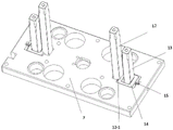
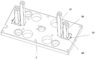
FIG. 5 is a schematic view of a three-dimensional structure of the utility model with a lower ejector rod, an inclined shovel, a base and a spring in a mold closing state;
FIG. 6 is a schematic perspective view of the cooperation of the lower ejector rod, the inclined shovel, the base and the spring in the ejection state of the present invention;
wherein: 1. an upper fixing plate; 2. a front mold template; 3. a rear mold template; 4. a support plate; 5. square iron; 6. an upper ejector plate; 7. a lower ejector plate; 8. a base plate;
9-1, a front mold cavity; 9-2, a rear mold cavity; 10. a core-pulling insert; 11. an insert fixing block;
12. a square ejector rod; 12-1, clamping grooves of the square ejector rods; 13. obliquely shoveling; 13-1, inclined plane of the inclined shovel; 14. a base; 14-1, a base inclined plane; 15. a spring.
Detailed Description
The preferred mechanisms and methods of motion realization of the present invention are further described below in conjunction with the figures and the detailed description.
As shown in fig. 1-6, a mold structure with a novel core pulling structure is a common simplified type fine water gap mold, and comprises an upper fixing plate 1, a front mold plate 2, a rear mold plate 3, a supporting plate 4, square irons 5 and a bottom plate 8 from top to bottom, wherein an upper ejector plate 6 and a lower ejector plate 7 are arranged between the square irons 5.
The front mould template 2 and the rear mould template 3 are respectively provided with a front mould cavity 9-1 and a rear mould cavity 9-2 which jointly form a cavity for forming an injection product.
The core-pulling mechanism is arranged on the rear die plate 3, the supporting plate 4, the upper ejector plate 6 and the lower ejector plate 7 and comprises a core-pulling insert 10, an insert fixing block 11, a square ejector rod 12, an inclined shovel 13, a base 14 and a spring 15.
As shown in fig. 2, the mold is of a bilateral symmetry structure, the core-pulling insert 10 is disposed in the center of the mold, the top of the core-pulling insert is inserted into the cavity, and the bottom of the core-pulling insert is fixed on the supporting plate 4 through an insert fixing block 10. When the mold is opened, the core-pulling insert 10 needs to be drawn out from the cavity, so that the core-pulling insert 10 is separated from the injection molding product.
As shown in fig. 2, the square top rod 12, the inclined blade 13, the base 14 and the spring 15 each include 2 pieces, and are symmetrically disposed on the left and right sides of the mold. For convenience of explanation, the right side of fig. 2 will be taken as an example for detailed explanation.
Go up thimble board 6 and thimble board 7 setting down between the square iron 5 of both sides, go up thimble board 6 and thimble board 7 down and pass through the screw fixation together, can upward movement or downstream simultaneously, the upside of going up thimble board 6 is layer board 4, and the downside of thimble board 7 down is bottom plate 8, goes up thimble board 6 and thimble board 7 down and can be between layer board 4 and bottom plate 8 synchronous up-and-down motion.
As shown in fig. 2, 5 and 6, the lower ejector plate 7 has grooves symmetrically formed on both left and right sides thereof, and the bases 14 are disposed in the grooves and can slide in the grooves. A base through hole is formed in the base 14, and a contact position of the base through hole and the inclined shovel 13 is set to be a base inclined surface 14-1.
The upper ejector plate 6 is arranged above the lower ejector plate 7, and the base 14 is limited in the groove of the lower ejector plate 7 to move.
As shown in fig. 2, the top of the square ejector rod 12 sequentially passes through the upper ejector plate 6 and the supporting plate 4, and is then fixedly connected with the rear die plate 3, and the bottom of the square ejector rod 12 extends into the groove of the lower ejector plate 7. The right side of the bottom of the square ejector rod 12 is provided with a square ejector rod clamping groove 12-1, when the front die template 2 and the rear die template 3 are closed, the left side of the base 14 is clamped at the square ejector rod clamping groove 12-1, namely the base 14 is clamped at the lower side of the square ejector rod 12, so that the base 14 can push the square ejector rod 12 to move upwards when the die is opened.
The top of the inclined shovel 13 penetrates through the upper ejector plate 6 and is fixed on the supporting plate 4, the bottom of the inclined shovel extends into a base through hole of the base 14, and an inclined shovel surface 13-1 matched with the base inclined surface 14-1 of the base 14 is arranged on the right side of the bottom of the inclined shovel 13.
The spring 15 is also arranged in a groove of the lower ejector plate 7, one end of which is fixed with the lower ejector plate 7 and the other end of which is fixed on the base 14. When the mold is closed, the spring 15 is in a compressed state and always provides a leftward thrust to the base 14, so that the base inclined surface 14-1 and the inclined shovel inclined surface 13-1 are pushed to keep a joint state.
When the mold is opened, when the base 14 moves upwards, the base 14 can move towards the right side along the inclined shovel surface 13-1 due to the action of the inclined shovel surface 13-1, so that the spring 15 is further pressed, and the spring 15 gives the pushing force for resetting the base 14.
The working process of the embodiment is as follows:
when the mold is used for injection molding, the front mold template 2 and the rear mold template 3 are in a mold closing state, at the moment, due to the action of the spring 15, the base inclined surface 14-1 is attached to the inclined shovel inclined surface 13-1 in the front mold template 2 and the rear mold template 3, the square ejector rod clamping groove 12-1 of the square ejector rod 12 is located above the base 14, and the square ejector rod 12 is clamped by the base 14 and cannot move downwards.
As shown in fig. 4 and 6, when the front mold platen 2 and the rear mold platen 3 are opened, a knock rod (not shown) of the mold is ejected to push the rear mold platen 3 to drive the injection product to move upward, and simultaneously, the upper ejector plate 6 and the lower ejector plate 7 move upward to drive the base 14 to push the ejector rod 12 upward and also to push the rear mold platen 3 to move upward, and the core-pulling insert 10 is fixed on the supporting plate 4 through the insert fixing block, and because the supporting plate 4 is stationary, the core-pulling insert 10 is also stationary, so that the core-pulling insert 10 is separated from the cavity, that is, the core pulling is realized.
On the other hand, because the top of the inclined shovel 13 is fixed on the supporting plate 4, the supporting plate 4 is fixed, the inclined shovel 13 is also fixed, the upper ejector plate 6 and the lower ejector plate 7 move upwards, and meanwhile, the base 14 is driven to move towards the right side in the groove of the lower ejector plate 7 along the inclined plane 13-1 of the inclined shovel, and the spring 14 is further pressed towards the right side.
As shown in fig. 3 and 5, when the front mold platen 2 and the rear mold platen 3 are closed again, the rear mold platen 3 drives the square ejector rods to move downwards, the upper ejector plate 6 and the lower ejector plate 7 move downwards at the same time, and the base 14 is reset along the inclined shovel surface 13-1 under the thrust action of the spring 14 until one end of the base 14 is reset to the position of the square ejector rod clamping groove 12-1.
In the whole motion process, due to the positioning action of the square ejector rod 12 and the inclined shovel 13, the whole core pulling process is smoother, and the core pulling is not smooth and blocked due to dislocation, the weight of the die and other reasons.
Finally, it should be noted that: although the present invention has been described in detail with reference to the embodiments, it will be apparent to those skilled in the art that modifications may be made to the embodiments or portions thereof without departing from the spirit and scope of the utility model.
Claims (8)
1. The mold structure with the novel core pulling structure comprises a rear mold plate (3) and a lower ejector plate (7), and is characterized in that the core pulling structure comprises a core pulling insert (10), a square ejector rod (12), an inclined shovel (13) and a base (14), wherein the core pulling insert (10) extends into a rear mold cavity of the rear mold plate (3), the base (14) is arranged in the lower ejector plate (7), the square ejector rod (12) is clamped above the base (14), the inclined shovel (13) is provided with an inclined shovel slope (13-1), and the base (14) is attached to the inclined shovel slope (13-1);
when the mold is opened, the rear mold plate (3) and the lower ejector plate (7) both move upwards, the lower ejector plate (7) drives the base (14) to move upwards so as to push the square ejector rod (12) to move upwards, the core-pulling insert (10) is conveniently separated from the rear mold cavity of the rear mold plate (3), and meanwhile, the lower ejector plate (7) drives the base (14) to move upwards along the inclined shovel slope (13-1).
2. The mold structure with the novel core pulling structure is characterized in that the core pulling structure further comprises a spring (15), one end of the spring (15) is connected with the lower ejector plate (7), the other end of the spring is connected with the base, and the base is always pushed by a pushing force moving towards the inclined shovel (13).
3. The mold structure with the novel core pulling structure according to claim 2, wherein the square ejector rod (12), the inclined shovel (13), the base (14) and the spring (15) comprise 2, and the two side ejector rods are respectively symmetrically arranged on two sides of the core pulling insert (10).
4. The mold structure with the novel core pulling structure is characterized by further comprising a supporting plate (4), the core pulling structure further comprises an insert fixing block (11), and the bottom of the core pulling insert (10) is fixed on the supporting plate (4) through the insert fixing block (11).
5. The mold structure with the novel core pulling structure is characterized in that the top of the square ejector rod (12) is fixedly connected with the rear mold plate (3), the bottom of the square ejector rod is provided with a square ejector rod clamping groove (12-1), and the square ejector rod clamping groove (12-1) is clamped above the base (14).
6. The mold structure with the novel core pulling structure is characterized in that the top of the inclined shovel (13) is connected with the supporting plate (4), a base inclined surface (14-1) is arranged at the contact position of the base (14) and the inclined shovel (13), and the base inclined surface (14-1) is attached to the inclined shovel inclined surface (13-1).
7. The mold structure with the novel core pulling structure is characterized in that the mold structure further comprises an upper ejector plate (6), the upper ejector plate (6) is fixedly connected with the lower ejector plate (7) and moves synchronously, and the upper ejector plate (6) limits the base (14) to move in the lower ejector plate (7).
8. The mold structure with the novel core pulling structure according to claim 2, wherein during mold closing, the rear mold plate (3) and the lower ejector plate (7) both move downward, the lower ejector plate (7) drives the base (14) to reset along the inclined shovel slope (13-1) under the thrust of the spring (15), the rear mold plate (3) drives the square ejector rod (12) to reset, and the square ejector rod clamping groove (12-1) is clamped above the base (14).
Priority Applications (1)
| Application Number | Priority Date | Filing Date | Title |
|---|---|---|---|
| CN202121149888.7U CN215396648U (en) | 2021-05-26 | 2021-05-26 | Mould structure with novel core pulling structure |
Applications Claiming Priority (1)
| Application Number | Priority Date | Filing Date | Title |
|---|---|---|---|
| CN202121149888.7U CN215396648U (en) | 2021-05-26 | 2021-05-26 | Mould structure with novel core pulling structure |
Publications (1)
| Publication Number | Publication Date |
|---|---|
| CN215396648U true CN215396648U (en) | 2022-01-04 |
Family
ID=79677564
Family Applications (1)
| Application Number | Title | Priority Date | Filing Date |
|---|---|---|---|
| CN202121149888.7U Active CN215396648U (en) | 2021-05-26 | 2021-05-26 | Mould structure with novel core pulling structure |
Country Status (1)
| Country | Link |
|---|---|
| CN (1) | CN215396648U (en) |
Cited By (1)
| Publication number | Priority date | Publication date | Assignee | Title |
|---|---|---|---|---|
| CN116653231A (en) * | 2023-07-25 | 2023-08-29 | 成都宝利根创科电子有限公司 | Demolding core-pulling mechanism for multi-surface core-pulling same-side demolding and injection mold |
-
2021
- 2021-05-26 CN CN202121149888.7U patent/CN215396648U/en active Active
Cited By (2)
| Publication number | Priority date | Publication date | Assignee | Title |
|---|---|---|---|---|
| CN116653231A (en) * | 2023-07-25 | 2023-08-29 | 成都宝利根创科电子有限公司 | Demolding core-pulling mechanism for multi-surface core-pulling same-side demolding and injection mold |
| CN116653231B (en) * | 2023-07-25 | 2023-10-24 | 成都宝利根创科电子有限公司 | Demolding core-pulling mechanism for multi-surface core-pulling same-side demolding and injection mold |
Similar Documents
| Publication | Publication Date | Title |
|---|---|---|
| CN113320104A (en) | Injection mold quick ejection mechanism based on efficient demolding | |
| CN215396648U (en) | Mould structure with novel core pulling structure | |
| CN110154327B (en) | Blind core-pulling mechanism of injection mold | |
| CN108015982B (en) | Injection mold for core pulling of inclined sliding block driven by movable mold pulling plate | |
| WO2023040049A1 (en) | Injection mold intersecting inclined ejection and removal mechanism | |
| CN215095410U (en) | Side plate back-off clamping and demolding mechanism of injection mold of frying pan | |
| CN111703029B (en) | Linkage inclined core pulling structure and core pulling method thereof | |
| CN211416097U (en) | Product ejection and demolding device | |
| CN103640191A (en) | Mechanism for separating plastic products from slide blocks on four sides | |
| CN218399270U (en) | Novel rear mold core pulling structure | |
| CN218519081U (en) | Mutual inductor shell forming die | |
| CN218948359U (en) | Mechanical front and rear die demolding structure | |
| CN219405261U (en) | Female die core-pulling mechanism of multi-cavity material reducing head | |
| CN113246411B (en) | Secondary ejection oblique demoulding mechanism | |
| CN211842979U (en) | Inclined core-pulling injection mold for movable mold | |
| CN213618165U (en) | Automatic ejection mechanism for movable mold insert | |
| CN219748804U (en) | Power mechanism for plastic mold core pulling | |
| CN219028346U (en) | Upper and lower cover mould | |
| CN217252593U (en) | Multi-cavity nozzle wax mold die | |
| CN213166586U (en) | Die capable of realizing delayed drawing action of sliding block | |
| CN216152964U (en) | Female die inclined ejection forming structure at frame opening buckle | |
| CN218640244U (en) | Plastic terminal mould with slide ejection function | |
| CN213440621U (en) | Mould of quick replacement mould benevolence | |
| CN203739148U (en) | Injection mold capable of achieving forced demolding | |
| CN215661526U (en) | Forming die for producing toy gun |
Legal Events
| Date | Code | Title | Description |
|---|---|---|---|
| GR01 | Patent grant | ||
| GR01 | Patent grant |