CN215391653U - Forming device is used in processing of solar module aluminium frame - Google Patents
Forming device is used in processing of solar module aluminium frame Download PDFInfo
- Publication number
- CN215391653U CN215391653U CN202023105827.9U CN202023105827U CN215391653U CN 215391653 U CN215391653 U CN 215391653U CN 202023105827 U CN202023105827 U CN 202023105827U CN 215391653 U CN215391653 U CN 215391653U
- Authority
- CN
- China
- Prior art keywords
- pair
- frame
- processing
- forming device
- door
- Prior art date
- Legal status (The legal status is an assumption and is not a legal conclusion. Google has not performed a legal analysis and makes no representation as to the accuracy of the status listed.)
- Active
Links
Images


Classifications
-
- Y—GENERAL TAGGING OF NEW TECHNOLOGICAL DEVELOPMENTS; GENERAL TAGGING OF CROSS-SECTIONAL TECHNOLOGIES SPANNING OVER SEVERAL SECTIONS OF THE IPC; TECHNICAL SUBJECTS COVERED BY FORMER USPC CROSS-REFERENCE ART COLLECTIONS [XRACs] AND DIGESTS
- Y02—TECHNOLOGIES OR APPLICATIONS FOR MITIGATION OR ADAPTATION AGAINST CLIMATE CHANGE
- Y02E—REDUCTION OF GREENHOUSE GAS [GHG] EMISSIONS, RELATED TO ENERGY GENERATION, TRANSMISSION OR DISTRIBUTION
- Y02E10/00—Energy generation through renewable energy sources
- Y02E10/50—Photovoltaic [PV] energy
Abstract
The utility model discloses a forming device for processing an aluminum frame of a solar cell module, which comprises a workbench, wherein a first door-shaped frame is arranged on the workbench, an electric roller is arranged in the first door-shaped frame, a pair of first chutes are arranged in the first door-shaped frame, roller adjusting devices are arranged on the pair of first chutes, a second door-shaped frame is arranged on the workbench, an air cylinder is arranged on the second door-shaped frame, a pressing plate is arranged at the telescopic end of the air cylinder, a pair of slide rails are arranged on the workbench and positioned at two sides of a square base, and clamping devices are arranged on the pair of slide rails. Is beneficial to the transportation of the aluminum section and brings convenience to the use of people.
Description
Technical Field
The utility model relates to the technical field of aluminum profile processing, in particular to a forming device for processing an aluminum frame of a solar cell module.
Background
The plastic working of aluminum and aluminum alloy, should guarantee the product to reach the required dimensional accuracy, mechanical properties and good surface quality stable, unanimous, also pay attention to prevent mechanical damage and corrosion, control grain size and organizational structure, these quality requirements are mainly guaranteed by production technology and equipment, aluminum and its alloy generally have better plasticity, easy plastic working, some aluminum alloy still should carry on the alclad in order to improve corrosion resistance and processability, the utility model patent with publication No. CN209998123U discloses an aluminum section bar extrusion grinding apparatus automatic molding device, including the bottom case, welded fastening has the backup pad on the outside surface wall of both sides respectively at the top of the bottom case, welded fastening has the top case on the outside surface wall of the upper side of the backup pad, fixed mounting has the first motor through the bolt on the bottom inner wall of the top case, fixed connection has the second band pulley on the output shaft of the upper side of the first motor, second band pulley left side is connected with first band pulley through belt drive, first band pulley connection is fixed on first axis of rotation, there is first movable rod first axis of rotation inside through threaded connection, it is fixed with the stripper plate to connect on the terminal exterior wall of first movable rod downside, the stripper plate is established in the grinding apparatus top, however in actual life, this utility model does not possess the aluminium alloy of transmission and the various models of centre gripping, needs other equipment to carry out the auxiliary usage, and it is inconvenient to use.
SUMMERY OF THE UTILITY MODEL
Aiming at the defects of the prior art, the utility model provides a forming device for processing an aluminum frame of a solar cell module, which solves the problem that the existing device cannot transmit and clamp aluminum profiles of various types.
In order to achieve the purpose, the utility model is realized by the following technical scheme: the utility model provides a forming device is used in processing of solar module aluminium frame, includes the workstation, install first door type frame on the workstation, install electronic running roller in the first door type frame, be equipped with a pair of first spout in the first door type frame, it is a pair of install running roller adjusting device on the first spout, install second door type frame on the workstation, install the cylinder on the second door type frame, the clamp plate is installed to the flexible end of cylinder, install square base on the workstation, just be located on the workstation a pair of slide rail is installed to square base both sides, and is a pair of install clamping device on the slide rail, install ejecting device on the workstation, be equipped with the second spout in the workstation, install strutting arrangement in the second spout.
Preferably, the roller adjusting device comprises a pair of first sliders installed in the first sliding grooves, a pair of connecting shafts are arranged on the first sliders, a pair of rollers are installed between the connecting shafts, a pair of supports are installed on the connecting shafts, a pair of bearings are arranged between the two ends of each support and the corresponding connecting shaft, a third sliding groove is formed in the first door-shaped frame, a rack is arranged in the third sliding groove, one end of the rack is connected with the upper end of each support, a supporting plate is installed on the first door-shaped frame, a first driving motor is installed on the supporting plate, a driving gear is installed at the driving end of the first driving motor, and the driving gear is meshed with the rack.
Preferably, clamping device is including installing a pair of slider on the slide rail, and is a pair of two pairs of telescopic links are installed to the slider inboard, and is two pairs a pair of splint are installed to the flexible end of telescopic link, and is a pair of the rotatory a pair of bolt that has connect in the slider, and is a pair of splint and a pair of be equipped with a pair of division board between the bolt, it is a pair of be equipped with a pair of first fastening screw on the slider, it is a pair of sleeve and loop bar are installed respectively to the slider side, be equipped with the second fastening screw on the sleeve.
Preferably, ejection device is including installing supporting seat on the workstation, be equipped with the fourth spout in the supporting seat, be equipped with the slide bar in the fourth spout, the disc is installed to the slide bar upper end, the pulley is installed to the slide bar lower extreme, install second driving motor on the workstation, the cam is installed to second driving motor drive end, the cam with pulley sliding connection.
Preferably, the supporting device comprises a supporting frame installed in the second sliding groove, a limiting pin is installed at the side end of the supporting frame, and a plurality of jacks are arranged in the second sliding groove.
Preferably, the supporting seat is located on one side of the square base.
Preferably, a backing plate is mounted at the bottom of the pair of first sliding chutes.
Preferably, the square base is located right below the pressing plate.
Advantageous effects
The utility model provides a forming device for processing an aluminum frame of a solar cell module, which has the following beneficial effects: the device has the advantages of compact structure, a first door-shaped frame is arranged on the workbench, electric rollers and roller adjusting devices are arranged in the first door-shaped frame, the up-and-down movement of the rollers can be controlled by starting a first driving motor, thereby controlling the clamping distance between the electric roller and the roller and realizing the clamping of aluminum profiles of various types, the utility model is provided with a sliding rail on the workbench, the slide rail is provided with a clamping device which can realize the preliminary clamping of the die through the adjustment of the sleeve and the loop bar, then the bolt is screwed to adjust the clamping plate on the sliding block for further clamping to prevent the mould from moving, meanwhile, the supporting device is arranged on the platform, so that the aluminum profile at the tail part can be supported, the feeding is facilitated, and the convenience is brought to the use of people.
Drawings
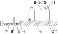
Fig. 1 is a front view of the present invention.
Fig. 2 is a schematic structural view of the roller adjusting device of the present invention.
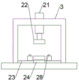
Fig. 3 is a front view of the clamping device of the present invention.
Fig. 4 is a top view of the clamping device of the present invention.
Fig. 5 is a schematic structural diagram of the ejection device of the present invention.
In the figure: 1. a work table; 2. a first gate frame; 3. a second portal frame; 4. a second chute; 5. a support frame; 6. a spacing pin; 7. a jack; 8. a support plate; 9. a first drive motor; 10. a driving gear; 11. a rack; 12. a third chute; 13. a support; 14. a roller; 15. a first chute; 16. a bearing; 17. a first slider; 18. a connecting shaft; 19. a base plate; 20. an electric roller; 21. a cylinder; 22. pressing a plate; 23. a slide rail; 24. a square base; 25. a splint; 26. a telescopic rod; 27. a slider; 28. a first fastening screw; 29. a bolt; 30. a loop bar; 31. a second fastening screw; 32. a sleeve; 33. a supporting seat; 34. a fourth chute; 35. a disc; 36. a slide bar; 37. a pulley; 38. a cam; 39. a second drive motor; 40. and (4) a partition board.
Detailed Description
The technical solutions in the embodiments of the present invention will be clearly and completely described below with reference to the drawings in the embodiments of the present invention, and it is obvious that the described embodiments are only a part of the embodiments of the present invention, and not all of the embodiments. All other embodiments, which can be derived by a person skilled in the art from the embodiments given herein without making any creative effort, shall fall within the protection scope of the present invention.
Referring to fig. 1-5, the present invention provides a technical solution: a forming device for processing an aluminum frame of a solar cell module comprises a workbench 1, wherein a first door-shaped frame 2 is installed on the workbench 1, an electric roller 20 is installed in the first door-shaped frame 2, a pair of first chutes 15 are arranged in the first door-shaped frame 2, a roller adjusting device is installed on the first chutes 15, a second door-shaped frame 3 is installed on the workbench 1, an air cylinder 21 is installed on the second door-shaped frame 3, a pressing plate 22 is installed at the telescopic end of the air cylinder 21, a square base 24 is installed on the workbench 1, a pair of slide rails 23 are installed on the workbench 1 and located on two sides of the square base 24, clamping devices are installed on the pair of slide rails 23, an ejection device is installed on the workbench 1, a second chute 4 is arranged in the workbench 1, and a supporting device is installed in the second chute 4, the roller adjusting device comprises a pair of first sliding blocks 17 arranged in a pair of first sliding grooves 15, a pair of connecting shafts 18 are arranged on the pair of first sliding blocks 17, a roller 14 is arranged between the pair of connecting shafts 18, a support 13 is arranged on the pair of connecting shafts 18, a pair of bearings 16 are arranged between the two ends of the support 13 and the pair of connecting shafts 18, a third sliding groove 12 is arranged on the first door-shaped frame 2, a rack 11 is arranged in the third sliding groove 12, one end of the rack 11 is connected with the upper end of the support 13, a support plate 8 is arranged on the first door-shaped frame 2, a first driving motor 9 is arranged on the support plate 8, a driving gear 10 is arranged on the first driving motor 9, the driving gear 10 is meshed with the rack 11, and the clamping device comprises a pair of sliding blocks 27 arranged on a pair of sliding rails 23, two pairs of telescopic rods 26 are mounted on the inner sides of the pair of sliding blocks 27, a pair of clamping plates 25 are mounted at the telescopic ends of the two pairs of telescopic rods 26, a pair of bolts 29 are screwed in the pair of sliding blocks 27, a pair of isolation plates 40 are arranged between the pair of clamping plates 25 and the pair of bolts 29, a pair of first fastening screws 28 are arranged on the pair of sliding blocks 27, a sleeve 32 and a loop bar 30 are respectively mounted at the side ends of the pair of sliding blocks 27, a second fastening screw 31 is arranged on the sleeve 32, the ejection device comprises a supporting seat 33 mounted on the workbench 1, a fourth sliding groove 34 is arranged in the supporting seat 33, a sliding rod 36 is arranged in the fourth sliding groove 34, a disc 35 is mounted at the upper end of the sliding rod 36, a pulley 37 is mounted at the lower end of the sliding rod 36, a second driving motor 39 is mounted on the workbench 1, and a cam 38 is mounted at the driving end of the second driving motor 39, cam 38 with pulley 37 sliding connection, strutting arrangement is including installing support frame 5 in the second spout 4, spacer pin 6 is installed to the 5 sides of support frame, be equipped with a plurality of jacks 7 of quantity in the second spout 4, supporting seat 33 is located square base 24 one side, it is a pair of backing plate 19 is installed to first spout 15 bottom, square base 24 is located under clamp plate 22.
The following working principles, detailed connecting means thereof, and the following main descriptions of the working principles and processes thereof are well known in the art, and will be referred to by those skilled in the art for the specific connection and operation sequence of the components in the present disclosure.
Example (b): when aluminum profiles are required to be processed, firstly, a first driving motor 9 on a supporting plate 8 is controlled, a driving gear 10 on a driving end of the first driving motor 9 rotates to drive a rack 11 meshed with the first driving motor to move up and down in a third sliding groove 12, the rack 11 drives a roller 14 to move in a first sliding groove 15 in a first door-shaped frame 2 through a support 13, so that aluminum profiles of various types and sizes are clamped, then a mold is placed on a square base 24, then a sleeve 32 and a loop bar 30 are moved to enable a sliding block 27 to move relatively on a sliding rail 23, then a second fastening screw 31 is screwed down to achieve preliminary clamping of the mold, then a bolt 29 on the sliding block 27 is screwed, the bolt 29 pushes a clamping plate 25 to achieve further clamping, then an air cylinder 21 on a second door-shaped frame 3 is started, a pressing plate 22 is made to extrude downwards, then a second driving motor 39 is started, the cam 38 on the driving end of the second driving motor 39 rotates, the pulley 37 connected with the cam in a sliding way drives the sliding rod 36 to move up and down in the fourth sliding chute 34, the sliding rod 36 drives the aluminum profile above to eject out through the disc 35, and finally the electric roller 20 drives the aluminum profile to move out, so that the use is convenient.
It is noted that, herein, relational terms such as first and second, and the like may be used solely to distinguish one entity or action from another entity or action without necessarily requiring or implying any actual such relationship or order between such entities or actions. Also, the terms "comprises," "comprising," or any other variation thereof, are intended to cover a non-exclusive inclusion, such that a process, method, article, or apparatus that comprises a list of elements does not include only those elements but may include other elements not expressly listed or inherent to such process, method, article, or apparatus. Without further limitation. The use of the phrase "comprising one of the elements does not exclude the presence of other like elements in the process, method, article, or apparatus that comprises the element.
Although embodiments of the present invention have been shown and described, it will be appreciated by those skilled in the art that changes, modifications, substitutions and alterations can be made in these embodiments without departing from the principles and spirit of the utility model, the scope of which is defined in the appended claims and their equivalents.
Claims (8)
1. The utility model provides a forming device is used in processing of solar module aluminium frame, includes workstation (1), its characterized in that, install first door type frame (2) on workstation (1), install electronic running roller (20) in first door type frame (2), be equipped with a pair of first spout (15) in first door type frame (2), it is a pair of install running roller adjusting device on first spout (15), install second door type frame (3) on workstation (1), install cylinder (21) on second door type frame (3), clamp plate (22) are installed to the flexible end of cylinder (21), install square base (24) on workstation (1), on workstation (1) and be located a pair of slide rail (23) are installed to square base (24) both sides, it is a pair of install clamping device on slide rail (23), the ejection device is installed on the workbench (1), a second sliding groove (4) is arranged in the workbench (1), and a supporting device is installed in the second sliding groove (4).
2. The forming device for processing the aluminum frame of the solar cell module according to claim 1, wherein the roller adjusting device comprises a pair of first sliding blocks (17) arranged in a pair of first sliding grooves (15), a pair of connecting shafts (18) are arranged on the pair of first sliding blocks (17), a roller (14) is arranged between the pair of connecting shafts (18), a bracket (13) is arranged on the pair of connecting shafts (18), a pair of bearings (16) are arranged between two ends of the bracket (13) and the pair of connecting shafts (18), a third sliding groove (12) is arranged on the first door-shaped frame (2), a rack (11) is arranged in the third sliding groove (12), one end of the rack (11) is connected with the upper end of the bracket (13), a supporting plate (8) is arranged on the first door-shaped frame (2), a first driving motor (9) is arranged on the supporting plate (8), a driving gear (10) is installed at the driving end of the first driving motor (9), and the driving gear (10) is meshed with the rack (11).
3. The forming device for processing the aluminum frame of the solar cell module according to claim 1, wherein the clamping device comprises a pair of sliding blocks (27) mounted on a pair of the sliding rails (23), two pairs of telescopic rods (26) are mounted on the inner sides of the pair of sliding blocks (27), a pair of clamping plates (25) are mounted at the telescopic ends of the two pairs of telescopic rods (26), a pair of bolts (29) are screwed in the pair of sliding blocks (27), a pair of isolation plates (40) are arranged between the pair of clamping plates (25) and the pair of bolts (29), a pair of first fastening screws (28) are arranged on the pair of sliding blocks (27), a pair of sleeves (32) and a sleeve rod (30) are respectively mounted at the side ends of the sliding blocks (27), and second fastening screws (31) are arranged on the sleeves (32).
4. The forming device for processing the aluminum frame of the solar cell module according to claim 1, wherein the ejection device comprises a support seat (33) installed on the workbench (1), a fourth chute (34) is arranged in the support seat (33), a slide bar (36) is arranged in the fourth chute (34), a disc (35) is installed at the upper end of the slide bar (36), a pulley (37) is installed at the lower end of the slide bar (36), a second driving motor (39) is installed on the workbench (1), a cam (38) is installed at the driving end of the second driving motor (39), and the cam (38) is slidably connected with the pulley (37).
5. The forming device for processing the aluminum frame of the solar cell module according to claim 1, wherein the supporting device comprises a supporting frame (5) installed in the second sliding groove (4), a limiting pin (6) is installed at a side end of the supporting frame (5), and a plurality of insertion holes (7) are formed in the second sliding groove (4).
6. The forming device for processing the aluminum frame of the solar cell module as claimed in claim 4, wherein the supporting seat (33) is located at one side of the square base (24).
7. The forming device for processing the aluminum frame of the solar cell module as claimed in claim 5, wherein a backing plate (19) is mounted at the bottom of the pair of first chutes (15).
8. The forming device for processing the aluminum frame of the solar cell module as claimed in claim 1, wherein the square base (24) is located right below the pressing plate (22).
Priority Applications (1)
| Application Number | Priority Date | Filing Date | Title |
|---|---|---|---|
| CN202023105827.9U CN215391653U (en) | 2020-12-22 | 2020-12-22 | Forming device is used in processing of solar module aluminium frame |
Applications Claiming Priority (1)
| Application Number | Priority Date | Filing Date | Title |
|---|---|---|---|
| CN202023105827.9U CN215391653U (en) | 2020-12-22 | 2020-12-22 | Forming device is used in processing of solar module aluminium frame |
Publications (1)
| Publication Number | Publication Date |
|---|---|
| CN215391653U true CN215391653U (en) | 2022-01-04 |
Family
ID=79637453
Family Applications (1)
| Application Number | Title | Priority Date | Filing Date |
|---|---|---|---|
| CN202023105827.9U Active CN215391653U (en) | 2020-12-22 | 2020-12-22 | Forming device is used in processing of solar module aluminium frame |
Country Status (1)
| Country | Link |
|---|---|
| CN (1) | CN215391653U (en) |
-
2020
- 2020-12-22 CN CN202023105827.9U patent/CN215391653U/en active Active
Similar Documents
| Publication | Publication Date | Title |
|---|---|---|
| CN214719918U (en) | Full-automatic stamping die of diesel generator rotor | |
| CN217191753U (en) | Steel sheet processing is with opening flat-bed machine that has surface structure of clearing up in advance | |
| CN215391653U (en) | Forming device is used in processing of solar module aluminium frame | |
| CN211310662U (en) | Movable support for die | |
| CN209971478U (en) | Polymer plastic pipe extrusion moulding equipment | |
| CN115283512B (en) | Automatic rolling device for processing aluminum alloy plate | |
| CN114261696B (en) | Section bar framing production line and framing method thereof | |
| CN215697479U (en) | Electronic wiring board punching machine integrating discharging and feeding | |
| CN213079575U (en) | Aluminum profile traction machine | |
| CN212979185U (en) | Extruded sheet ejection of compact forming device | |
| CN205061069U (en) | Transmission device of rolling up is rolled up to aluminium | |
| CN210334002U (en) | Aluminum template pressing plate convenient to use | |
| CN114393136A (en) | Anti-extrusion processing jig for strip steel sleeve product | |
| CN217800011U (en) | Rolling device for cylinder sleeve of oxygen generator | |
| CN218835961U (en) | Extrusion forming device for cable bridge | |
| CN111229942A (en) | Two bending die strips and bender of 90 degrees of bending make progress | |
| CN218963648U (en) | Copper processing extrusion device | |
| CN214855816U (en) | Full-automatic electric blanket all-in-one | |
| CN217599767U (en) | Adjustable feeding equipment for production and processing of die steel | |
| CN213915554U (en) | Low-temperature correction device for deformed steel | |
| CN218775387U (en) | Four-roller frame | |
| CN215143935U (en) | Mould embryo performing device of complicated precision mould | |
| CN218700540U (en) | Plastic mold clamping mechanism | |
| CN210411983U (en) | Auto-parts serial number printing die | |
| CN219966989U (en) | Quick roll changing device |
Legal Events
| Date | Code | Title | Description |
|---|---|---|---|
| GR01 | Patent grant | ||
| GR01 | Patent grant |