CN215386378U - Auxiliary device is changed to normal position dialysis catheter - Google Patents
Auxiliary device is changed to normal position dialysis catheter Download PDFInfo
- Publication number
- CN215386378U CN215386378U CN202121736697.0U CN202121736697U CN215386378U CN 215386378 U CN215386378 U CN 215386378U CN 202121736697 U CN202121736697 U CN 202121736697U CN 215386378 U CN215386378 U CN 215386378U
- Authority
- CN
- China
- Prior art keywords
- pipe
- tube
- replacement
- catheter
- dialysis
- Prior art date
- Legal status (The legal status is an assumption and is not a legal conclusion. Google has not performed a legal analysis and makes no representation as to the accuracy of the status listed.)
- Active
Links
Images


Abstract
The utility model provides an auxiliary device is changed to normal position dialysis catheter, the seal wire passes puncture tube in proper order, along with puncture tube sharp tip puncture the check barrier and pass guide catheter, pass the dialysis catheter who is connected with the connecting pipe along guide catheter, penetrate the human body along dialysis catheter. Compared with the prior art, the utility model has the advantages that in the process of hemodialysis catheter replacement, the guide wire enters the blood vessel, thus obviously reducing the outward seepage loss of blood in the catheter along the guide wire and the catheter lumen; serious complications such as air embolism and the like caused by the fact that air enters the body along with the guide wire are avoided; the contact with the original catheter in the operation process is reduced, so that the sterile area in the operation process is cleaner, the infection incidence is reduced, an operator can complete the operation easily, and the safety of the newly-placed catheter and the effect of the new catheter are relatively improved. In addition, the injection connecting pipe is connected with the injector, the reason of the original catheter dysfunction can be distinguished through side hole radiography, the local blood vessel condition can be evaluated, and a better catheter treatment scheme is provided.
Description
Technical Field
The utility model relates to the field of medical appliance articles, in particular to an in-situ dialysis catheter replacement auxiliary device.
Background
Hemodialysis, also known as artificial kidney or kidney washing in popular parlance, is called hemodialysis for short, and is one of the blood purification techniques. The blood purification device utilizes the principle of a semipermeable membrane, and achieves the purposes of purifying blood and correcting water electrolyte and acid-base balance by dispersing and removing various harmful and redundant metabolic wastes and excessive electrolytes in the body.
In clinic, hemodialysis catheter placement is typically accomplished using a hemodialysis catheter and guidewire in combination, the hemodialysis catheter being used to create a short-term venous access for hemodialysis, blood collection, manometry, and fluid infusion; the guide wire plays the roles of leading, supporting, opening and exchanging in the blood vessel intervention. However, in practical use, the temporary dialysis catheter is often replaced with a hemodialysis catheter in situ due to poor function or long-term dialysis catheter, during the replacement process, the guide wire is led into a blood vessel of a human body, and blood is leaked and lost due to the existence of a gap between the guide wire and the original catheter cavity, or air enters the human body through the guide wire, so that serious complications such as air embolism are caused. In the operation process, the original catheter needs to be contacted to be placed into the guide wire, and aseptic area pollution is caused (the external catheter is aseptic, and the external catheter is directly contacted to reduce pollution). If the guide wire needs to be placed under intervention, the syringe is required to be used for injecting the contrast agent from the catheter port, then the syringe is pulled out to replace the guide wire, and the operation process is complex, so that the operation time is increased, and the pollution risk is increased.
SUMMERY OF THE UTILITY MODEL
The utility model aims to solve the technical problems that in the original position replacement process of a dialysis catheter, a guide wire enters a blood vessel to cause massive bleeding of the blood vessel and air enters the blood vessel to aggravate the disease condition.
An in-situ dialysis catheter replacement auxiliary device comprises a guide wire, a dialysis catheter and a replacement part movably connected with the dialysis catheter, wherein the guide wire sequentially passes through the replacement part and a tube opening of the dialysis catheter to enter a human body; the replacement part comprises a first replacement pipe, a second replacement pipe, a puncture pipe, a guide catheter, a grid baffle and a grid baffle, the first replacement pipe comprises a connecting pipe and a dialysis connecting pipe, the pipe orifice of the dialysis connecting pipe is movably connected with the pipe orifice of the dialysis catheter, the pipe orifice of the connecting pipe is movably connected with the pipe orifice at one end of the second replacement pipe, the puncture pipe penetrates into the second replacement pipe from the pipe orifice at the other end of the second replacement pipe, the puncture pipe is integrally conical, the sharp end of the puncture pipe is contacted with the grid baffle, and the gentle end part of the puncture pipe is exposed out of the second replacement pipe; the connecting pipe is movably connected with the grid blocking piece at the edge of the pipe orifice connected with the second replacement pipe, the grid blocking piece covers the pipe orifice of the connecting pipe, and the grid blocking film is arranged on the grid blocking piece and covers the open hole formed in the center of the grid blocking piece; the guide catheter is arranged in the connecting pipe, a pipe orifice at one end of the guide catheter penetrates through the opening of the dialysis connecting pipe and is arranged in the dialysis connecting pipe, a pipe orifice at the other end of the guide catheter contacts the grid baffle and surrounds the periphery of the grid baffle, and the guide catheter is provided with a plurality of catheter holes along the length direction of the pipe wall; the guide wire penetrates through the puncture tube in sequence, penetrates through the guide catheter along with the sharp end of the puncture tube poking the grid breaking barrier membrane, penetrates through the dialysis catheter connected with the connecting tube along the guide catheter, and penetrates into the human body along the dialysis catheter.
In the technical scheme of the utility model, in the replacement process, the guide wire sequentially passes through the puncture tube, penetrates through the guide catheter along with the sharp end of the puncture tube piercing the grid breaking baffle membrane, penetrates through the dialysis catheter connected with the connecting tube along the guide catheter, and penetrates into the human body along the dialysis catheter, so that the problem that the puncture point bleeds greatly or air enters into the human body along with the guide wire due to the fact that the guide wire enters into the human body once because of manipulations and the characteristics of the guide wire or needs long time is avoided.
Preferably, the wall of the dialysis connecting pipe is provided with an injection connecting pipe connected with the injector, and the injection connecting pipe is provided with a water stop valve for stopping the injector from injecting liquid.
In the technical scheme of the utility model, the injection connecting pipe is arranged to be conveniently connected with the injector, the injector is connected with the dialysis catheter, so that liquid can be injected into the body by avoiding secondary puncture, the arranged water stop valve is convenient for opening the valve when in use, the injector injects the liquid, and when not applicable, the valve is closed to prevent the liquid in the injector from entering the human body.
Preferably, the connecting pipe is provided with a shielding block for blocking the pipe orifice of the guide catheter arranged in the connecting pipe, the pipe wall of the connecting pipe is provided with an opening for the shielding block to go in and out, two side faces of the shielding block, which are contacted with the pipe wall, are provided with symmetrical bulges, and the diameter of the shielding block is larger than that of the pipe orifice of the guide catheter.
In the technical scheme of the utility model, the shielding block covers the pipe orifice of the guide catheter, so that the condition of reverse flow of the injector during injection is avoided, and the position of the shielding block can be limited by the protrusion arranged on the shielding block.
Preferably, the in-situ dialysis catheter replacement auxiliary device further comprises a supporting part for connecting the reinforcing syringe with the replacement part, wherein the supporting part comprises a first pipe clamp, a second pipe clamp and a supporting rod, the first pipe clamp is clamped on the injection tube of the syringe and locked and fixed through a fastening piece, the second pipe clamp is clamped on the first replacement tube and locked and fixed through a fastening piece, and the two pipe clamps are respectively hinged with one end of the supporting rod and fixedly connected between the reinforcing syringe and the replacement part through nuts.
In the technical scheme of the utility model, the support part can reinforce the connection between the injector and the replacement part, the two pipe clamps are respectively clamped on the injector and the first replacement pipe body and are fixed through the fasteners, the disassembly and the assembly are convenient, and the two pipe clamps are hinged with the support rod, and the angle can be adjusted according to requirements.
Preferably, the diameter of the orifice of the guide catheter is larger than the diameter of the overlying barrier membrane. In the technical scheme of the utility model, the diameter of the nozzle of the guide catheter is larger than that of the covered grid baffle film, so that the guide wire can extend along the guide direction of the guide catheter after extending out of the grid baffle film.
Preferably, the joint of the first replacement pipe and the second replacement pipe is provided with an external thread, the second replacement pipe is provided with a corresponding internal thread, and the first replacement pipe and the second replacement pipe are connected through a thread. In the technical scheme of the utility model, the threaded connection is convenient to combine and the operation is simple.
Preferably, the joint of the puncture tube and the second replacement tube is provided with an external thread, the second replacement tube is provided with a corresponding internal thread, the puncture tube is connected with the second replacement tube through the thread, the puncture tube rotates towards the grid barrier along the thread, and the sharp end of the puncture tube rotates to penetrate through the grid barrier. In the technical scheme of the utility model, the puncture tube and the second replacement tube are connected by screw threads and are convenient to combine, and the puncture tube can also rotate to penetrate the check barrier film along the direction of the screw threads.
Preferably, the grid baffle is provided with a clamping block correspondingly clamped with the clamping groove at the edge of the pipe orifice of the first replacement pipe, and the grid baffle and the first replacement pipe are clamped and fixed in the clamping groove through the clamping block. In the technical scheme of the utility model, the grid blocking piece is connected with the first replacement pipe in a clamping way, so that the operation is simple and easy.
Preferably, first replacement pipe and second replacement pipe all adopt transparent PVC material, and the puncture pipe also adopts transparent PVC material to make. In the technical scheme of the utility model, the condition in the pipe is convenient to observe by adopting the transparent PVC material.
Preferably, the dialysis connecting tube is in threaded connection with the dialysis catheter, and the injection connecting tube is in threaded connection with the injector. In the technical scheme of the utility model, the threaded connection is convenient to connect and simple to operate.
Compared with the prior art, the utility model has the beneficial effects that: the guide wire sequentially penetrates through the puncture tube, penetrates through the guide catheter along with the sharp end of the puncture tube poking the grid breaking barrier membrane, penetrates through the dialysis catheter connected with the connecting tube along the guide catheter, and penetrates into a human body along the dialysis catheter; serious complications such as air embolism and the like caused by the fact that air enters the body along with the guide wire are avoided; the contact with the original catheter in the operation process is reduced, so that the sterile area in the operation process is cleaner, the infection incidence is reduced, an operator can complete the operation easily, and the safety of the newly-placed catheter and the effect of the new catheter are relatively improved. In addition, the injection connecting pipe is connected with the injector, the reason of the original catheter dysfunction can be distinguished through side hole radiography, the local blood vessel condition can be evaluated, and a better catheter treatment scheme is provided.
Drawings
Fig. 1 is a schematic view of the overall structure of the present invention (hiding the syringe and the support portion).
Fig. 2 is a schematic view of a tube structure of the displacement portion of the present invention.
Fig. 3 is a schematic view of the tube structure of the displacement portion (hiding the second displacement tube) according to the present invention.
FIG. 4 is a cross-sectional view of the displacement section tube according to the present invention.
FIG. 5 is a front view of the tube of the displacement portion of the present invention.
Fig. 6 is a schematic view of the overall structure of the present invention.
Fig. 7 is a schematic cross-sectional view of the overall structure of the present invention.
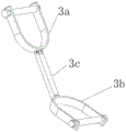
Fig. 8 is a schematic structural view of the supporting portion of the present invention.
Detailed Description
The technical solutions in the embodiments of the present invention will be described in detail below with reference to fig. 1 to 8 in the embodiments of the present invention.
It is obvious that the described embodiments are only a part of the embodiments of the present invention, and not all embodiments, and all other embodiments obtained by those skilled in the art without any inventive work are within the scope of the present invention based on the embodiments of the present invention. In the description of the present invention, it should be noted that the terms "center", "upper", "lower", "left", "right", "vertical", "horizontal", "inner", "outer", etc., indicate orientations or positional relationships based on the orientations or positional relationships shown in the drawings, and are only for convenience of description and simplicity of description, but do not indicate or imply that the device or element being referred to must have a particular orientation, be constructed and operated in a particular orientation, and thus, should not be construed as limiting the present invention. Furthermore, the terms "first," "second," and "third" are used for descriptive purposes only and are not to be construed as indicating or implying relative importance. In the description of the present invention, it should be noted that, unless otherwise explicitly specified or limited, the terms "mounted," "connected," and "connected" are to be construed broadly, e.g., as meaning either a fixed connection, a removable connection, or an integral connection; can be mechanically or electrically connected; the two elements can be directly connected or indirectly connected through an intermediate medium, and the two elements can be communicated with each other, so that the specific meaning of the terms in the utility model can be understood by those skilled in the art.
The guide wire, the injector, the dialysis catheter and the like mentioned in the technical scheme of the utility model are all mentioned in the prior art, and the operation and the use method are all well known to the ordinary skilled person.
Example 1
As shown in fig. 1-3, an in-situ dialysis catheter replacement auxiliary device comprises a guide wire 2, a dialysis catheter 5 and a replacement part 1 in threaded connection with the dialysis catheter 5, wherein the guide wire 2 sequentially passes through the replacement part 1 and the orifice of the dialysis catheter 5 to enter the human body; the replacement part 1 comprises a first replacement tube 1a, a second replacement tube 1b, a puncture tube 1c, a guide catheter 1d, a grid baffle 1e and a grid baffle 1f, wherein the first replacement tube 1a and the second replacement tube 1b are both made of transparent PVC materials, and the puncture tube 1c is also made of transparent PVC materials; first replacement pipe 1a includes connecting pipe 1j and dialysis threaded connection pipe 1j, and the mouth of pipe of dialysis connecting pipe 1k and the mouth of pipe threaded connection of dialysis pipe 5 set up the injection connecting pipe 1g of connecting syringe 4 on the pipe wall of dialysis connecting pipe 1k, set up the stagnant water valve 1h that blocks syringe 4 injection liquid on injection connecting pipe 1 g.
As shown in fig. 1-7, the joint of the first displacement pipe 1a and the second displacement pipe 1b is provided with an external thread, the second displacement pipe 1b is provided with a corresponding internal thread, and the first displacement pipe 1a and the second displacement pipe 1b are connected by a thread; the puncture tube 1c penetrates into the second replacement tube 1b from the tube opening at the other end of the second replacement tube 1b, the tube opening through which the guide wire 2 penetrates is formed in the puncture tube 1c, the puncture tube 1c is integrally conical, the sharp end of the puncture tube 1c is in contact with the lattice barrier film 1f, the gentle end portion of the puncture tube 1c is exposed outside the second replacement tube 1b, the joint of the puncture tube 1c and the second replacement tube 1b is provided with an external thread, the second replacement tube 1b is provided with a corresponding internal thread, the puncture tube 1c is in threaded connection with the second replacement tube 1b, the puncture tube 1c rotates towards the lattice barrier film 1f along the threads, and then the sharp end of the puncture tube 1c rotates to penetrate through the lattice barrier film 1 f. The connecting pipe 1j is movably connected with the grid baffle plate 1e at the edge of the pipe orifice connected with the second replacement pipe 1b, a clamping block correspondingly clamped with a clamping groove at the edge of the pipe orifice of the first replacement pipe 1a is arranged on the grid baffle plate 1e, the grid baffle plate 1e and the first replacement pipe 1a are clamped and fixed in the clamping groove through the clamping block, the grid baffle plate 1e covers the pipe orifice of the connecting pipe 1j, the grid baffle film 1f is adhered or pressed on the grid baffle plate 1e and covers an open hole arranged at the center of the grid baffle plate 1e, the guide conduit 1d is arranged in the connecting pipe 1j, the pipe orifice at one end of the guide conduit 1d penetrates through the open hole of the dialysis connecting pipe 1k to be dialyzed and arranged in the connecting pipe 1k, the pipe orifice at the other end contacts the grid baffle plate 1e, the diameter of the guide conduit 1d is larger than that of the covered grid baffle film 1f, the pipe orifice of the guide conduit 1d surrounds the periphery of the grid baffle film 1f, the guide wire 2 penetrates out of the grid baffle film 1f, then, the blood is guided along the guide tube 1d to pass through the dialysis connection tube 1k and then to pass through the dialysis tube 5 into the human body.
As shown in fig. 1 to 7, the guide conduit 1d is provided with a plurality of conduit holes, for example, two conduit holes, along the length direction of the conduit wall, the connecting conduit 1j is provided with a shielding block 1i for blocking the conduit opening of the guide conduit 1d arranged in the connecting conduit 1j, the conduit wall of the connecting conduit 1j is provided with an opening for the shielding block 1i to go in and out, two side surfaces of the shielding block 1i contacting with the conduit wall are provided with symmetrical protrusions, and the diameter of the shielding block 1i is larger than the diameter of the conduit opening of the guide conduit 1 d. The guide wire 2 sequentially penetrates through the puncture tube 1c, penetrates through the guide catheter 1d along with the sharp end of the puncture tube 1c poking the grid breaking barrier membrane 1f, penetrates through the dialysis catheter 5 connected with the connecting tube 1j along the guide catheter 1d, and penetrates into the human body along the dialysis catheter 5.
As shown in fig. 4-8, the device for in-situ replacement of dialysis catheter 5 further comprises a support portion 3 for reinforcing the connection of the syringe 4 and the replacement portion 1, wherein the support portion 3 comprises a first tube clip 3a, a second tube clip 3b and a support rod 3c, wherein the first tube clip 3a is clamped on the syringe of the syringe 4 and is fastened and fixed by a fastener, the second tube clip 3b is clamped on the first replacement tube 1a and is fastened and fixed by a fastener, and the two tube clips are respectively hinged with one end of the support rod 3c and are used for fixing the connection between the syringe 4 and the replacement portion 1 by a nut.
The operation principle and the process of the utility model are as follows: the dialysis catheter 5 of a patient needs to be replaced at regular time in hemodialysis to avoid infection, when the dialysis catheter 5 is replaced, plugging liquid is firstly injected into the first replacement tube 1a, then the grid block sheet 1e is clamped into the clamping groove of the first replacement pipe 1a to seal the first replacement pipe 1a, then the first substitution tube 1a is connected with the second substitution tube 1b, and then the dialysis connection tube 1k of the first substitution tube 1a is unplugged and connected with the dialysis catheter 5, then the puncture tube 1c is rotationally pushed along the screw thread from the tube opening at the bottom of the second replacement tube 1b, the sharp end of the puncture tube 1c punctures the check baffle film 1f, the guide wire 2 sequentially passes through the puncture tube 1c and the first replacement tube 1a along the guide catheter 1d arranged in the second replacement tube 1b, then, the blood passes through the dialysis catheter 5 and then passes along the dialysis catheter 5 into the human body, and the in-situ replacement is performed. The guide wire 2 sequentially penetrates through the puncture tube 1c, penetrates through the guide catheter 1d along with the puncture of the sharp end of the puncture tube 1c and the grid breaking barrier membrane 1f, penetrates through the dialysis catheter 5 connected with the connecting tube 1j along the guide catheter 1d, and penetrates into a human body along the dialysis catheter 5, and in the replacement process of the dialysis catheter 5, the guide wire 2 enters a blood vessel, so that the outward seepage loss of blood in the catheter along the guide wire 2 and a catheter lumen with a gap is obviously reduced; serious complications such as air embolism and the like caused by the fact that air enters the body along with the guide wire are avoided; the contact with the original catheter in the operation process is reduced, so that the sterile area in the operation process is cleaner, the infection incidence is reduced, an operator can complete the operation easily, and the safety of the newly-placed catheter and the effect of the new catheter are relatively improved.
The injector 4 filled with contrast medium or other liquid can be connected with the injection connecting pipe 1g of the first replacement pipe 1a according to requirements, corresponding liquid is injected into a human body, the reason of the original poor function of the catheter is distinguished, the local blood vessel condition is evaluated, and a better catheter treatment scheme is provided, and when the injector 4 injects liquid, in order to avoid the liquid from flowing backwards into the first replacement pipe 1a, the shielding block 1i can be used for shielding the pipe orifice of the guide catheter 1d positioned in the first replacement pipe 1 a.
The above embodiments are only for illustrating the technical idea of the present invention, and the protection scope of the present invention is not limited thereby, and any modifications made on the basis of the technical scheme according to the technical idea of the present invention fall within the protection scope of the present invention.
Claims (10)
1. An in-situ dialysis catheter replacement auxiliary device comprises a guide wire (2) and a dialysis catheter (5), and is characterized by further comprising a replacement part (1) movably connected with the dialysis catheter (5), wherein the guide wire (2) sequentially passes through the replacement part (1) and a tube opening of the dialysis catheter (5) to enter a human body;
the replacement part (1) comprises a first replacement tube (1 a), a second replacement tube (1 b), a puncture tube (1 c), a guide catheter (1 d), a grid baffle sheet (1 e) and a grid baffle film (1 f), the first replacement tube (1 a) comprises a connecting tube (1j) and a dialysis connecting tube (1k), the tube orifice of the dialysis connecting tube (1k) is movably connected with the tube orifice of the dialysis catheter (5), the tube orifice of the connecting tube (1j) is movably connected with the tube orifice at one end of the second replacement tube (1 b), the puncture tube (1 c) penetrates into the second replacement tube (1 b) from the tube orifice at the other end of the second replacement tube (1 b), the puncture tube (1 c) is integrally conical, the sharp end of the puncture tube (1 c) is in contact with the grid baffle film (1 f), and the gentle end part of the puncture tube (1 c) is exposed out of the second replacement tube (1 b);
the edge of the pipe orifice connected with the second replacement pipe (1 b) of the connecting pipe (1j) is movably connected with the lattice blocking piece (1 e), the lattice blocking piece (1 e) covers the pipe orifice of the connecting pipe (1j), and the lattice blocking film (1 f) is arranged on the lattice blocking piece (1 e) and covers the open hole formed in the center of the lattice blocking piece (1 e);
the guide catheter (1 d) is arranged in the connecting pipe (1j), a pipe orifice at one end of the guide catheter (1 d) penetrates through the opening of the dialysis connecting pipe (1k) and is arranged in the dialysis connecting pipe (1k), a pipe orifice at the other end of the guide catheter (1 d) is in contact with the lattice blocking piece (1 e) and surrounds the periphery of the lattice blocking film (1 f), and a plurality of catheter holes are formed in the guide catheter (1 d) along the length direction of the pipe wall;
the guide wire (2) sequentially penetrates through the puncture tube (1 c), penetrates through the guide catheter (1 d) along with the sharp end of the puncture tube (1 c) poking the grid breaking barrier membrane (1 f), penetrates through the dialysis catheter (5) connected with the connecting tube (1j) along the guide catheter (1 d), and penetrates into the human body along the dialysis catheter (5).
2. The in situ dialysis catheter exchange aid of claim 1, wherein: an injection connecting pipe (1 g) connected with the injector (4) is arranged on the pipe wall of the dialysis connecting pipe (1k), and a water stop valve (1 h) for stopping the injector (4) from injecting liquid is arranged on the injection connecting pipe (1 g).
3. The in situ dialysis catheter exchange aid of claim 1, wherein: the connecting pipe (1j) is provided with a shielding block (1 i) for blocking the pipe orifice of a guide conduit (1 d) arranged in the connecting pipe (1j), the pipe wall of the connecting pipe (1j) is provided with an opening for the shielding block (1 i) to go in and out, two side faces of the shielding block (1 i) contacted with the pipe wall are provided with symmetrical bulges, and the diameter of the shielding block (1 i) is larger than that of the pipe orifice of the guide conduit (1 d).
4. The in situ dialysis catheter exchange aid of claim 1, wherein: the utility model provides an auxiliary device is changed to normal position dialysis catheter still includes supporting part (3) that reinforcement syringe (4) and replacement portion (1) are connected, supporting part (3) include first pipe clamp (3 a), second pipe clamp (3 b) and bracing piece (3 c), wherein, first pipe clamp (3 a) centre gripping is fixed on the syringe of syringe (4) and through fastener locking, second pipe clamp (3 b) centre gripping is fixed on first replacement pipe (1 a) and through fastener locking, two pipe clamps are articulated and are fixed through the nut with one of them one end of bracing piece (3 c) respectively and are strengthened being connected between syringe (4) and replacement portion (1).
5. The in situ dialysis catheter exchange aid of claim 1, wherein: the diameter of the orifice of the guide conduit (1 d) is larger than that of the covered barrier film (1 f).
6. The in situ dialysis catheter exchange aid of claim 1, wherein: the joint of the first replacement pipe (1 a) and the second replacement pipe (1 b) is provided with an external thread, the second replacement pipe (1 b) is provided with a corresponding internal thread, and the first replacement pipe (1 a) is connected with the second replacement pipe (1 b) through a thread.
7. The in situ dialysis catheter exchange aid of claim 1, wherein: the joint of the puncture tube (1 c) and the second replacement tube (1 b) is provided with an external thread, the second replacement tube (1 b) is provided with a corresponding internal thread, the puncture tube (1 c) is in threaded connection with the second replacement tube (1 b), the puncture tube (1 c) rotates towards the direction of the lattice barrier film (1 f) along the threads, and the sharp end of the puncture tube (1 c) rotates to puncture the lattice barrier film (1 f).
8. The in situ dialysis catheter exchange aid of claim 1, wherein: the grid separation blade (1 e) is provided with a clamping block which is correspondingly clamped with the clamping groove at the edge of the pipe orifice of the first replacement pipe (1 a), and the grid separation blade (1 e) and the first replacement pipe (1 a) are clamped and fixed in the clamping groove through the clamping block.
9. The in situ dialysis catheter exchange aid of claim 1, wherein: the first replacement pipe (1 a) and the second replacement pipe (1 b) are both made of transparent PVC materials, and the puncture pipe (1 c) is also made of transparent PVC materials.
10. The in situ dialysis catheter exchange aid of claim 1, wherein: the dialysis connecting pipe (1k) is in threaded connection with the dialysis catheter (5), and the injection connecting pipe (1 g) is in threaded connection with the injector (4).
Priority Applications (1)
| Application Number | Priority Date | Filing Date | Title |
|---|---|---|---|
| CN202121736697.0U CN215386378U (en) | 2021-07-28 | 2021-07-28 | Auxiliary device is changed to normal position dialysis catheter |
Applications Claiming Priority (1)
| Application Number | Priority Date | Filing Date | Title |
|---|---|---|---|
| CN202121736697.0U CN215386378U (en) | 2021-07-28 | 2021-07-28 | Auxiliary device is changed to normal position dialysis catheter |
Publications (1)
| Publication Number | Publication Date |
|---|---|
| CN215386378U true CN215386378U (en) | 2022-01-04 |
Family
ID=79653842
Family Applications (1)
| Application Number | Title | Priority Date | Filing Date |
|---|---|---|---|
| CN202121736697.0U Active CN215386378U (en) | 2021-07-28 | 2021-07-28 | Auxiliary device is changed to normal position dialysis catheter |
Country Status (1)
| Country | Link |
|---|---|
| CN (1) | CN215386378U (en) |
-
2021
- 2021-07-28 CN CN202121736697.0U patent/CN215386378U/en active Active
Similar Documents
| Publication | Publication Date | Title |
|---|---|---|
| CN215386378U (en) | Auxiliary device is changed to normal position dialysis catheter | |
| CN113350597A (en) | Multifunctional auxiliary device for in-situ dialysis catheter replacement | |
| CN206934383U (en) | Drainage system and CVC external member | |
| CN205948162U (en) | Blood vessel route washing unit | |
| CN104645448A (en) | Anti-reflux remaining needle | |
| CN214633385U (en) | Extension tube for anesthesia | |
| CN210057135U (en) | High-cleanliness three-way valve for prolonging vein use | |
| CN217854023U (en) | Water injection device for alveolar lavage | |
| CN111772730A (en) | Thrombolytic drainage device | |
| CN215995090U (en) | Transfusion device switching tube capable of accurately judging needle insertion position by using sealing membrane | |
| CN219721464U (en) | Abdominal cavity drainage device | |
| CN219814887U (en) | Tube sealing device for preventing indwelling needle foreign matter from blocking | |
| CN216985896U (en) | Multi-head inserting device for bladder irrigation | |
| CN219516472U (en) | Disposable puncture needle for diagnosis stage | |
| CN211383375U (en) | Fixed-point puncture needle for hemodialysis internal fistula | |
| CN217187252U (en) | Novel quick-dismantling type anti-flow infusion joint | |
| CN217067213U (en) | Collection transfusion blood sampling integrative prevents that acupuncture hinders impotence pjncture needle | |
| CN210728317U (en) | Hemodialysis is with two side screw thread mouths side branch venous pot connecting pipe | |
| CN215083400U (en) | Anti-reflux remaining needle | |
| CN217793934U (en) | Improved hemodialysis pipeline | |
| CN217724210U (en) | Hemodialysis blood sampling and medicine connector | |
| CN215083397U (en) | Safe indwelling needle | |
| CN209092289U (en) | A kind of sterile anti-reflux body fluid drainage bag device | |
| CN210384509U (en) | Connecting pipeline for sodium citrate external anticoagulation | |
| CN215537109U (en) | Novel arteriovenous puncture needle |
Legal Events
| Date | Code | Title | Description |
|---|---|---|---|
| GR01 | Patent grant | ||
| GR01 | Patent grant |