CN215366457U - Cleaning assembly of cloth printing and dyeing device - Google Patents
Cleaning assembly of cloth printing and dyeing device Download PDFInfo
- Publication number
- CN215366457U CN215366457U CN202120998020.8U CN202120998020U CN215366457U CN 215366457 U CN215366457 U CN 215366457U CN 202120998020 U CN202120998020 U CN 202120998020U CN 215366457 U CN215366457 U CN 215366457U
- Authority
- CN
- China
- Prior art keywords
- cloth
- roller
- box
- box body
- cleaning
- Prior art date
- Legal status (The legal status is an assumption and is not a legal conclusion. Google has not performed a legal analysis and makes no representation as to the accuracy of the status listed.)
- Active
Links
Images


Abstract
The utility model belongs to the technical field of cloth printing and dyeing, and particularly relates to a cleaning assembly of a cloth printing and dyeing device, which comprises a box body, wherein a cloth placing roller is arranged on the left side of the box body, a cloth tightening frame is arranged on the upper left side of an inner cavity of the box body, a first cloth guide roller is arranged on the left side of the inner cavity of the box body and positioned on the lower right side of the cloth tightening frame, a cleaning part is arranged on the right side of the first cloth guide roller, a dust suction part is arranged on the right side of the cleaning part, a second cloth guide roller is arranged on the right side of the dust suction part, a sundry box is arranged on the left side of the inner cavity of the box body, a dust collector is connected to the right side of the sundry box through a pipeline, the dust collector is connected with the dust suction part through a hose, a printing and dyeing box is arranged on the right side of the box body, cloth is movably driven in the inner cavity of the box body, the cleaning assembly can effectively prevent the dust on the surface of the cloth from damaging the color and the redundant thread ends when the cloth is printed and dyed, thereby ensuring the quality of cloth printing and dyeing.
Description
Technical Field
The utility model relates to the technical field of cloth printing and dyeing, in particular to a cleaning assembly of a cloth printing and dyeing device.
Background
Dyeing and finishing are called again, are a cloth processing mode, also be the general name of pretreatment, dyeing, printing, after-treatment, washing water etc., along with the continuous improvement and the development of dyeing process technology, the fabrics design that dyes out is also abundant constantly, nevertheless remain stub and dust on the cloth during dyeing, can make the design and color printing and dyeing effect variation of cloth, so need clear away dust and unnecessary stub on the cloth before printing and dyeing, destroy the design and color when avoiding design and color printing and dyeing, guarantee the printing and dyeing quality of cloth.
SUMMERY OF THE UTILITY MODEL
The utility model aims to provide a cleaning assembly of a cloth printing and dyeing device, which aims to solve the problems that the dust and the redundant thread ends on the cloth need to be cleaned before printing and dyeing, the design and color of the cloth pattern are damaged during the design and dyeing, and the printing and dyeing quality of the cloth is ensured.
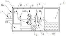
In order to achieve the purpose, the utility model provides the following technical scheme: a cleaning assembly of a cloth printing and dyeing device comprises a box body, wherein a cloth placing roller is installed on the left side of the box body, the front end of the cloth placing roller is connected with a first driving motor, a cloth tightening frame is arranged on the upper left side of an inner cavity of the box body, the middle of the cloth tightening frame is in a convex shape, a first cloth guide roller is movably arranged on the left side of the inner cavity of the box body and positioned on the lower right side of the cloth tightening frame, a cleaning part is movably arranged in the middle of the inner cavity of the box body and comprises an upper cleaning roller and a lower cleaning roller, the rear ends of the upper cleaning roller and the lower cleaning roller are connected with the inner wall of the box body through bearings, the front ends of the upper cleaning roller and the lower cleaning roller penetrate through the box body, gears are sleeved at the front ends of the upper cleaning roller and the lower cleaning roller, the two gears are meshed with each other, a second driving motor is connected at the front end of the upper cleaning roller, and the lower cleaning roller are identical in structure, the right side fixed mounting of clearance part has dust absorption part, movable mounting has the second fabric guide roller in the right side box of dust absorption part, box inner chamber left side below is provided with the miscellaneous case of collection, there is the dust catcher right side of the miscellaneous case of collection through the pipe connection, the dust catcher right side is passed through the hose and is connected with dust absorption part.
Preferably, the front ends of the first cloth guide roller and the second cloth guide roller penetrate through the box body, the front ends of the first cloth guide roller and the second cloth guide roller are respectively connected with a first belt pulley and a second belt pulley, and the first belt pulley is connected with the second belt pulley through a belt.
Preferably, a spiral circular knife is arranged on the right half side roller wall of the upper cleaning roller, and a soft brush is arranged on the left half side roller wall of the upper cleaning roller.
Preferably, the dust absorption part includes sucking disc, lower sucking disc, both sides all are connected with two connecting rods, four around the sucking disc, lower sucking disc the other end and the box inner wall fixed connection of connecting rod, go up the sucking disc and pass through the hose intercommunication with lower sucking disc, it is the same with the structure of lower sucking disc to go up the sucking disc.
Preferably, the upper sucker comprises a suction port and a suction box, the left end of the suction box is connected with the suction port, the inner side of the suction port is clamped with a separation net, and the bottom end of the suction box is provided with a soft cloth wiper.
Compared with the prior art, the utility model has the beneficial effects that:
1) this equipment clears away the dust on cloth surface and unnecessary end of a thread through cleaning element, dust absorption part, and the later stage cloth printing and dyeing work of being convenient for effectively avoids the cloth to destroy the design with unnecessary end of a thread dust when the design is printed and dyed to guarantee the quality of cloth printing and dyeing.
2) This equipment carries out the centre gripping clearance through last cleaning roller, lower cleaning roller to the cloth, prunes the end of a thread on the cloth through rotatory circular knife, brushes the end of a thread and the dust of pruning through the pappus brush and neatly, absorbs, accomodates through last sucking disc, lower sucking disc, reaches the two-sided clean and tidy effect of cloth.
Drawings
FIG. 1 is a front view cross-sectional structural schematic of the present invention;
FIG. 2 is a schematic top view, cross-sectional configuration of the present invention;
FIG. 3 is a front view cross-sectional structural schematic view of an upper scrub roller of the present invention;
FIG. 4 is a front view, cross-sectional structural schematic view of the upper sucker.
In the figure:
1 cloth feeding roller, 2 cloth tightening frames, 3 boxes, 4 first cloth guide rollers, 5 cleaning components, 51 upper cleaning rollers, 511 soft hairbrushes, 512 spiral rotary circular cutters, 52 lower cleaning rollers, 53 gears, 54 second driving motors, 6 dust suction components, 61 upper suction cups, 611 suction boxes, 612 suction ports, 613 separation nets, 614 soft cloth wipers, 62 lower suction cups, 63 connecting rods, 7 second cloth guide rollers, 8 hoses, 9 dust collectors, 10 impurity collecting boxes, 11 dye printing boxes, 12 first driving motors, 13 belts, 131 first belt pulleys, 132 second belt pulleys, 14 third driving motors and 15 cloth.
Detailed Description
The technical solutions in the embodiments of the present invention will be clearly and completely described below with reference to the drawings in the embodiments of the present invention, and it is obvious that the described embodiments are only a part of the embodiments of the present invention, and not all of the embodiments. All other embodiments, which can be derived by a person skilled in the art from the embodiments given herein without making any creative effort, shall fall within the protection scope of the present invention.
In the description of the present invention, it is to be understood that the terms "upper", "lower", "front", "rear", "left", "right", "top", "bottom", "inner", "outer", and the like, indicate orientations or positional relationships based on the orientations or positional relationships shown in the drawings, are merely for convenience in describing the present invention and simplifying the description, and do not indicate or imply that the device or element being referred to must have a particular orientation, be constructed and operated in a particular orientation, and thus, should not be construed as limiting the present invention.
Example (b):
referring to fig. 1-4, the present invention provides a technical solution: a cleaning assembly of a cloth printing and dyeing device comprises a box body 3, wherein a cloth placing roller 1 is installed on the left side of the box body 3, the front end of the cloth placing roller 1 is connected with a first driving motor 12, through the structure, the first driving motor 12 drives the cloth placing roller 1 to rotate to achieve cloth placing, a cloth tightening frame 2 is arranged on the upper left side of an inner cavity of the box body 3, the middle of the cloth tightening frame 2 is convex, a first cloth guide roller 4 is movably arranged on the left side of the inner cavity of the box body 3 and on the lower right side of the cloth tightening frame 2, a cleaning part 5 is movably arranged in the middle of the inner cavity of the box body 3, the cleaning part 5 comprises an upper cleaning roller 51 and a lower cleaning roller 52, the rear ends of the upper cleaning roller 51 and the lower cleaning roller 52 are connected with the inner wall of the box body 3 through bearings, the front ends of the upper cleaning roller 51 and the lower cleaning roller 52 penetrate through the box body 3, gears 53 are sleeved at the front ends of the upper cleaning roller 51 and the lower cleaning roller 52, the two gears 53 are meshed, the front end of the upper cleaning roller 51 is connected with a second driving motor 54, the upper cleaning roller 51 and the lower cleaning roller 52 have the same structure, through the structure, the second driving motor 54 rotates to drive the upper cleaning roller 51 and the gear 53 to rotate, the lower cleaning roller 52 is driven to rotate under the meshing of the gear 53, the upper cleaning roller 51 and the lower cleaning roller 52 rotate at a relatively high speed, the spiral circular knife 512 and the soft brush 511 are crossed to trim and brush cloth, the right side of the cleaning component 5 is fixedly provided with a dust collection component 6, a second cloth guide roller 7 is movably arranged in a right box body 3 of the dust collection component 6, a trash box 10 is arranged below the inner cavity of the box body 3, the right side of the trash box 10 is connected with a dust collector 9 through a pipeline, the right side of the dust collector 9 is connected with the dust collection component 6 through a hose 8, through the structure, the cleaning component 5 and the dust collection component 6 are matched to remove dust and redundant thread ends on the surface of the cloth 15, and then the dust and the redundant thread ends are conveyed to the impurity collecting box 10 through the hose 8 and the pipeline, so that the cloth 15 can be conveniently printed and dyed at the later stage, and the cleaned cloth is conveyed to the printing and dyeing box 11 to be printed and dyed.
The front end of first fabric guide roller 4, second fabric guide roller 7 all runs through box 3, the front end of first fabric guide roller 4, second fabric guide roller 7 is connected with first belt pulley 131, second belt pulley 132 respectively, first belt pulley 131 passes through belt 13 transmission with second belt pulley 132 and is connected, the front end of first fabric guide roller 4 is connected with third driving motor 14, and through above-mentioned structure, third driving motor 14 drives first fabric guide roller 4, first belt pulley 131 and rotates, drives second belt pulley 132, second fabric guide roller 7 and rotates under belt 13 transmission, realizes constantly conveying cloth 15 right.
The right half roller wall of the upper cleaning roller 51 is provided with a spiral circular knife 512, the left half roller wall of the upper cleaning roller 51 is paved with a soft brush 511, and through the structure, the spiral circular knife 512 and the soft brush 511 are crossed to trim and brush cloth.
The upper sucker 61 comprises a suction port 612 and a suction box 611, the suction port 612 is arranged at the left end of the suction box 611, a separation net 613 is clamped at the inner side of the suction port 612, a soft cloth wiper 614 is arranged at the bottom of the suction box 611, redundant thread ends and dust on the cloth 15 are sucked into the suction box 611 through the suction port 612 through the structure, the separation net effectively prevents the suction port 612 from clamping the cloth 15, and the soft cloth wiper 614 clamps the cloth 15 when the cloth 15 is conveyed rightwards, so that the effect of flattening the cloth 15 is achieved.
The working principle is as follows:
starting a first driving motor 12, a second driving motor 54 and a third driving motor 14, the first driving motor 12 driving a cloth releasing roller 1 to rotate to realize cloth releasing, the cloth 15 being unfolded by a cloth tightening frame 2, the third driving motor 14 driving a first cloth guide roller 4 and a first belt pulley 131 to rotate, driving a second belt pulley 132 and a second cloth guide roller 7 to rotate under the transmission action of a belt 13 to realize continuous rightward transmission of the cloth 15, the second driving motor 54 driving an upper cleaning roller 51 and a gear 53 to rotate, driving a lower cleaning roller 52 to rotate under the engagement of the gear 53, enabling the upper cleaning roller 51 and the lower cleaning roller 52 to rotate at a relatively high speed, trimming and brushing the cloth by a spiral circular knife 512 and a soft brush 511, starting a dust collector 9, generating suction by the dust collector 9 to suck redundant thread ends and dust on the cloth 15 into a suction box 611 through a 612, and then conveying the excess thread ends and the dust to a impurity collecting box 10 through a hose 8 and a pipeline, the cleaning assembly is movably driven to be provided with cloth 15, and the cloth is conveyed to the printing and dyeing box 11 to be printed and dyed after being cleaned.
While there have been shown and described the fundamental principles and essential features of the utility model and advantages thereof, it will be apparent to those skilled in the art that the utility model is not limited to the details of the foregoing exemplary embodiments, but is capable of other specific forms without departing from the spirit or essential characteristics thereof; the present embodiments are therefore to be considered in all respects as illustrative and not restrictive, the scope of the utility model being indicated by the appended claims rather than by the foregoing description, and all changes which come within the meaning and range of equivalency of the claims are therefore intended to be embraced therein, and any reference signs in the claims are not intended to be construed as limiting the claim concerned.
Although embodiments of the present invention have been shown and described, it will be appreciated by those skilled in the art that changes, modifications, substitutions and alterations can be made in these embodiments without departing from the principles and spirit of the utility model, the scope of which is defined in the appended claims and their equivalents.
Claims (5)
1. The utility model provides a clearance subassembly of cloth printing and dyeing device, includes box (3), its characterized in that: the cloth feeding device is characterized in that a cloth feeding roller (1) is installed on the left side of the box body (3), the front end of the cloth feeding roller (1) is connected with a first driving motor (12), a cloth tightening frame (2) is arranged on the upper left side of an inner cavity of the box body (3), the middle of the cloth tightening frame (2) is in a convex shape, a first cloth guide roller (4) is movably arranged on the left side of the inner cavity of the box body (3) and positioned below the right side of the cloth tightening frame (2), a cleaning part (5) is movably arranged in the middle of the inner cavity of the box body (3), the cleaning part (5) comprises an upper cleaning roller (51) and a lower cleaning roller (52), the rear ends of the upper cleaning roller (51) and the lower cleaning roller (52) are connected with the inner wall of the box body (3) through bearings, the front ends of the upper cleaning roller (51) and the lower cleaning roller (52) penetrate through the box body (3), gears (53) are sleeved on the front ends of the upper cleaning roller (51) and the lower cleaning roller (52), two gear (53) mesh mutually, the front end of going up cleaning roller (51) is connected with second driving motor (54), it is the same with the structure of lower cleaning roller (52) to go up cleaning roller (51), the right side fixed mounting of cleaning means (5) has dust collecting part (6), movable mounting has second fabric guide roller (7) in the right side box (3) of dust collecting part (6), box (3) inner chamber left side below is provided with collection miscellaneous case (10), there is dust catcher (9) right side through the pipe connection of collection miscellaneous case (10), dust catcher (9) right side is passed through hose (8) and is connected with dust collecting part (6).
2. A cleaning assembly for a cloth printing apparatus according to claim 1, wherein: the front end of first fabric guide roller (4), second fabric guide roller (7) all run through box (3), the front end of first fabric guide roller (4), second fabric guide roller (7) is connected with first belt pulley (131), second belt pulley (132) respectively, first belt pulley (131) are connected through belt (13) transmission with second belt pulley (132), the front end of first fabric guide roller (4) is connected with third driving motor (14).
3. A cleaning assembly for a cloth printing apparatus according to claim 1, wherein: the right half side roller wall of the upper cleaning roller (51) is provided with a spiral circular knife (512), and the left half side roller wall of the upper cleaning roller (51) is paved with a soft brush (511).
4. A cleaning assembly for a cloth printing apparatus according to claim 1, wherein: dust absorption part (6) include sucking disc (61), lower sucking disc (62), both sides all are connected with two connecting rods (63), four around sucking disc (61), lower sucking disc (62) the other end and box (3) inner wall fixed connection of connecting rod (63), go up sucking disc (61) and lower sucking disc (62) and pass through hose (8) intercommunication, it is the same with the structure of lower sucking disc (62) to go up sucking disc (61).
5. A cleaning assembly for a cloth printing apparatus according to claim 4, wherein: the upper sucker (61) comprises a suction port (612) and a suction box (611), the suction port (612) is arranged at the left end of the suction box (611), a separation net (613) is clamped at the inner side of the suction port (612), and a soft cloth wiper (614) is installed at the bottom of the suction box (611).
Priority Applications (1)
| Application Number | Priority Date | Filing Date | Title |
|---|---|---|---|
| CN202120998020.8U CN215366457U (en) | 2021-05-11 | 2021-05-11 | Cleaning assembly of cloth printing and dyeing device |
Applications Claiming Priority (1)
| Application Number | Priority Date | Filing Date | Title |
|---|---|---|---|
| CN202120998020.8U CN215366457U (en) | 2021-05-11 | 2021-05-11 | Cleaning assembly of cloth printing and dyeing device |
Publications (1)
| Publication Number | Publication Date |
|---|---|
| CN215366457U true CN215366457U (en) | 2021-12-31 |
Family
ID=79629655
Family Applications (1)
| Application Number | Title | Priority Date | Filing Date |
|---|---|---|---|
| CN202120998020.8U Active CN215366457U (en) | 2021-05-11 | 2021-05-11 | Cleaning assembly of cloth printing and dyeing device |
Country Status (1)
| Country | Link |
|---|---|
| CN (1) | CN215366457U (en) |
Cited By (1)
| Publication number | Priority date | Publication date | Assignee | Title |
|---|---|---|---|---|
| CN115432504A (en) * | 2022-08-24 | 2022-12-06 | 常熟市金尧服装机械有限公司 | High-precision automatic cloth paving system |
-
2021
- 2021-05-11 CN CN202120998020.8U patent/CN215366457U/en active Active
Cited By (1)
| Publication number | Priority date | Publication date | Assignee | Title |
|---|---|---|---|---|
| CN115432504A (en) * | 2022-08-24 | 2022-12-06 | 常熟市金尧服装机械有限公司 | High-precision automatic cloth paving system |
Similar Documents
| Publication | Publication Date | Title |
|---|---|---|
| CN215366457U (en) | Cleaning assembly of cloth printing and dyeing device | |
| CN109898256B (en) | Clothing unhairing machine | |
| CN113148763A (en) | Automatic cone winder with yarn cleaning function | |
| CN112475600A (en) | Cloth deckle edge remove device for textile sector | |
| CN110355155B (en) | Conveniently remove belt cleaning device for car pipeline of oil stain | |
| CN112474463A (en) | Photovoltaic cleaning device for photovoltaic intelligent power station | |
| CN115056065A (en) | Special-shaped plate side edge processing machine | |
| CN212714058U (en) | Textile fabric cleaning device | |
| CN215362054U (en) | Packaging and conveying device for garment processing workshop | |
| CN211003783U (en) | Weaving is with weaving cloth conveyer | |
| CN212335508U (en) | Belt cleaning device for textile fabric | |
| CN213866983U (en) | Thread layer carding device for spinning | |
| CN212152751U (en) | Device capable of removing dust and cutting miscellaneous threads of printing and dyeing cloth | |
| CN113695298A (en) | Relief cloth processing device and processing method thereof | |
| CN220564942U (en) | Clothing cloth of fabrics cuts out dust removal cleaning device in advance | |
| CN218779204U (en) | Weaving cotton processing is with two-sided burring device | |
| CN216474134U (en) | Weaving processing is with weaving dirt clearing device | |
| CN110965303A (en) | Double-station type synthetic fiber cloth surface attachment cleaning device | |
| CN217231610U (en) | Road sweeper with garbage recoverer | |
| CN220613328U (en) | Grinding device that wardrobe processing production used | |
| CN215314432U (en) | A cloth feeding end dust collector for surface fabric compounding machine | |
| CN217973669U (en) | Scrubbing structure for fabric textile cleaning processing | |
| CN215101081U (en) | Cloth printing and dyeing is with tiling equipment | |
| CN214400979U (en) | Cloth belt cleaning device is used in gauze mask production | |
| CN218356038U (en) | Rotary type desktop small object cleaning equipment |
Legal Events
| Date | Code | Title | Description |
|---|---|---|---|
| GR01 | Patent grant | ||
| GR01 | Patent grant |