CN215364461U - Adjustable hoisting device - Google Patents
Adjustable hoisting device Download PDFInfo
- Publication number
- CN215364461U CN215364461U CN202120452128.7U CN202120452128U CN215364461U CN 215364461 U CN215364461 U CN 215364461U CN 202120452128 U CN202120452128 U CN 202120452128U CN 215364461 U CN215364461 U CN 215364461U
- Authority
- CN
- China
- Prior art keywords
- hoisting
- horizontal
- locking
- vertical
- ring
- Prior art date
- Legal status (The legal status is an assumption and is not a legal conclusion. Google has not performed a legal analysis and makes no representation as to the accuracy of the status listed.)
- Active
Links
Images


Landscapes
- Load-Engaging Elements For Cranes (AREA)
Abstract
The utility model discloses an adjustable hoisting device, which comprises a lifting hook, a sling and a hoisting tool, wherein the hoisting tool comprises a hoisting lock clamp, the upper side of the hoisting lock clamp is fixedly connected with a supporting seat, the upper side of the supporting seat is fixedly connected with a vertical fixed block, the upper side of the vertical fixed block is fixedly connected with a vertical eye ring, and the vertical eye ring is movably connected with a vertical hoisting ring; a horizontal fixing block is fixedly connected to the left side of the hoisting lock clamp, a horizontal eye ring is fixedly connected to the horizontal fixing block, and a horizontal hoisting ring is movably connected to the horizontal eye ring; one side of horizontal fixed block is provided with two sets of locking bolt, locking bolt's screw thread end is provided with the activity and protects and fills up, the protection fill up with be provided with between the hoist and mount collet and hang the material mouth. The utility model has the advantages of low cost, simple structure, convenient assembly and disassembly, convenient popularization and small use limitation, and is suitable for skins, composite materials, aluminum plates and the like with thin and long parts.
Description
Technical Field
The utility model belongs to the technical field of aircraft skin hoisting, and particularly relates to an adjustable hoisting device.
Background
The aircraft skin has the function of maintaining the appearance of the aircraft, so that the aircraft has good aerodynamic characteristics, the skin bears the aerodynamic action and transmits the acting force to the connected wing framework of the aircraft body, the stress is complex, and in addition, the skin is directly contacted with the outside, so that the skin material is required to have high strength, good plasticity, smooth surface and high corrosion resistance; because the skin adopts numerical control machining process part expansion size great (8000 ~16000 mm), it is crucial whether hoist and mount, transportation, clamping mode select to reasonably concern the deformation of woollen and part before numerical control milling process, however current hoist device when hoist and mount great skin of length, can not freely adjust the quantity of hoist and mount point and hoist and mount device according to the length of woollen/part, and the protectiveness to its woollen and part is poor, needs an adjustable hoist device to solve this problem.
SUMMERY OF THE UTILITY MODEL
The utility model aims to overcome the defects in the background art and provide an adjustable hoisting device. In order to achieve the purpose, the utility model adopts the following technical scheme:
an adjustable hoisting device comprises a lifting hook, a sling and a hoisting tool, wherein the hoisting tool comprises a hoisting lock clamp, the upper side of the hoisting lock clamp is fixedly connected with a supporting seat, the upper side of the supporting seat is fixedly connected with a vertical fixed block, the upper side of the vertical fixed block is fixedly connected with a vertical eye ring, and the vertical eye ring is movably connected with a vertical hoisting ring; a horizontal fixing block is fixedly connected to the left side of the hoisting lock clamp, a horizontal eye ring is fixedly connected to the horizontal fixing block, and a horizontal hoisting ring is movably connected to the horizontal eye ring; one side of horizontal fixed block is provided with two sets of locking bolt, locking bolt passes through the locking hole that sets up the left side of hoist and mount collet, locking bolt's screw thread end is provided with movable protection and fills up, the protection fill up with be provided with between the hoist and mount collet and hang the material mouth.
Preferably, the hoisting locking clamp is of a U-shaped structure.
Preferably, the two groups of locking bolts are parallel to each other and located on the same horizontal line.
Preferably, the surface of the protection pad is provided with anti-skid lines.
Preferably, the vertical hoisting ring and the horizontal hoisting ring are identical in structure and are alloy steel hoisting rings.
Preferably, the locking hole is an M16 hole, and the locking bolt is in threaded connection with the locking hole.
Preferably, the sling is a G80 manganese steel chain, and the lifting hook is a reinforced claw lifting hook and is provided with a self-locking device.
Preferably, the lifting appliance is made of 30CrMnSi, and the end face of the locking bolt is of a rounded corner R5 structure.
Compared with the prior art, the utility model has the beneficial effects that:
1. the utility model has the advantages of low cost, simple structure, convenient assembly and disassembly and convenient popularization, can freely adjust the number of hoisting points and hoisting devices according to the length of the wool/parts by arranging the hoisting locking clamp, the horizontal hoisting ring and the vertical hoisting ring, has small use limitation, and is suitable for skin, composite materials, aluminum plates and the like with thin and large parts.
2. Through all setting up vertical hoisting ring and horizontal hoisting ring into alloy steel rings to and the hoist cable sets up to G80 manganese steel chain and lifting hook and sets up to consolidating the goat's horn lifting hook and have self-lock device, such hoist device is durable, and whole hoist and mount in-process risk is little.
3. The hanger is made of 30CrMnSi, so that the strength and the enough toughness of the hanger are guaranteed, the end face of the locking bolt is designed into a fillet R5 structure, and the scratch to personnel and skin parts is reduced in the using process.
4. The hoisting locking clamp is provided with the locking hole and the locking bolt, the locking bolt is in threaded connection with the locking hole, and the locking hole is an M16 hole, so that the effect of locking the skin woolen/part can be achieved when hoisting is carried out in parallel; when the device is used for vertical hoisting, the locking bolt is inserted into the prefabricated phi 17 of the skin part and then is in threaded connection with the M16 hole on the hoisting device, so that the device realizes two functions of parallel hoisting and vertical hoisting.
Drawings
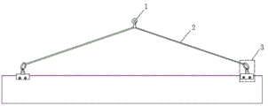
FIG. 1 is a schematic view of the overall structure of an adjustable lifting device of the present invention;
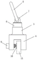
FIG. 2 is a schematic view of a vertical hoisting structure in an adjustable hoisting device according to the present invention;
FIG. 3 is a schematic view of a horizontal hoisting structure in an adjustable hoisting device according to the present invention;
figure 4 is a top view of a horizontal hoist in an adjustable hoist of the present invention.
Reference numerals: 1. a hook; 2. a sling; 3. a spreader; 4. hoisting a locking clamp; 5. a supporting seat; 6. a vertical fixing block; 7. a vertical eye ring; 8. a vertical hoisting ring; 9. locking the bolt; 10. a protective pad; 11. a material hanging port; 12. a horizontal fixed block; 13. a horizontal eye ring; 14. and (5) horizontally hoisting the ring.
Detailed Description
To further understand and appreciate the structural features and functions of the present invention, it should be noted that in the present application, the terms "upper", "left", "horizontal", "vertical", and the like refer to the orientation or positional relationship based on the drawings. These terms are used primarily to better describe the present application and its embodiments, and are not used to limit the indicated devices, elements or components to a particular orientation or to be constructed and operated in a particular orientation. The present application will now be described in detail with reference to the following examples, with reference to the accompanying drawings, wherein:
the embodiment provides an adjustable hoisting device, which comprises a lifting hook 1, a sling 2 and a hoisting tool 3, wherein the hoisting tool 3 comprises a hoisting lock clamp 4, a support seat 5 is fixedly connected to the upper side of the hoisting lock clamp 4, a vertical fixed block 6 is fixedly connected to the upper side of the support seat 5, a vertical eye ring 7 is fixedly connected to the upper side of the vertical fixed block 6, and a vertical hoisting ring 8 is movably connected to the vertical eye ring 7; a horizontal fixing block 12 is fixedly connected to the left side of the hoisting locking clamp 4, a horizontal eye ring 13 is fixedly connected to the horizontal fixing block 12, and a horizontal hoisting ring 14 is movably connected to the horizontal eye ring 13; one side of horizontal fixed block 12 is provided with two sets of locking bolt 9, and locking bolt 9 passes the left side of hoist and mount collet 4 through the locking hole that sets up, and locking bolt 9's screw thread end is provided with movable protection pad 10, is provided with between protection pad 10 and the hoist and mount collet 4 and hangs material mouth 11.
In one embodiment of the present application, the lifting locking clip 4 is a U-shaped structure.
In one embodiment of the present application, the two sets of locking bolts 9 are parallel to each other and located on the same horizontal line.
In one embodiment of the present application, the surface of the protective pad 10 is provided with anti-slip lines.
In an embodiment of the present application, the vertical hoisting ring 8 and the horizontal hoisting ring 14 have the same structure and are both alloy steel hoisting rings.
In one embodiment of the present application, the locking hole is an M16 hole, and the locking bolt 9 is threadedly coupled to the locking hole.
In one embodiment of the application, the sling 2 is a G80 manganese steel chain, and the hook 1 is a reinforced claw hook with a self-locking device.
In one embodiment of the present application, the hanger 3 is made of 30CrMnSi, and the end face of the locking bolt 9 is in a rounded R5 structure.
The technical scheme and principle of the utility model are as follows: the utility model can be used in two modes of horizontal hoisting and vertical hoisting, wherein the horizontal hoisting comprises the following steps: firstly, measuring the length of a part by using a measuring tape, ensuring that the suspended part outside a blank/part hoisting device is 1/5 of the total length, marking the position of the hoisting device on a blank/part by using a marking pen, and enabling the corresponding hoisting device to be on an axis; the edge of the non-processing surface of the skin is inserted into the arranged hanging material port 11 by arranging the hanging material port 11 on the hoisting locking clamp 4, and meanwhile, the arranged protection pad 10 is placed on the upper surface of the skin, so that the skin parts are prevented from being crushed; and then the two groups of locking bolts 9 are locked in a stress application manner, the end faces of the locking bolts 9 are designed into a fillet R5 structure, so that the skin parts are prevented from being scratched in the stress application process of the bolts, the hooks of the sling 2 are hung on parallel hoisting rings, and the whole parallel hoisting installation is completed.
And (3) vertical hoisting: firstly, when a numerical control planomiller is used for processing a front skin part, a 4-phi 17 hole is prefabricated on one side and is used as a vertical hoisting fixing hole, and the suspended part is 1/5 of the total length; the skin is inserted into the arranged hanging material opening 11, the locking bolt 9 is aligned to the pre-fabricated 4-phi 17 hole and locked, the hook of the hanging rope 2 is hung on the vertical hanging ring 8, and the whole vertical hanging installation is completed.
The foregoing is a more detailed description of the utility model in connection with specific preferred embodiments and it is not intended that the utility model be limited to these specific details. For those skilled in the art to which the utility model pertains, several simple deductions or substitutions can be made without departing from the spirit of the utility model, and all shall be considered as belonging to the protection scope of the utility model.
Claims (8)
1. The utility model provides an adjustable hoisting device, includes lifting hook (1), hoist cable (2) and hoist (3), its characterized in that: the lifting appliance (3) comprises a lifting locking clamp (4), a supporting seat (5) is fixedly connected to the upper side of the lifting locking clamp (4), a vertical fixing block (6) is fixedly connected to the upper side of the supporting seat (5), a vertical eye ring (7) is fixedly connected to the upper side of the vertical fixing block (6), and a vertical lifting ring (8) is movably connected to the vertical eye ring (7); a horizontal fixing block (12) is fixedly connected to the left side of the hoisting locking clamp (4), a horizontal eye ring (13) is fixedly connected to the horizontal fixing block (12), and a horizontal hoisting ring (14) is movably connected to the horizontal eye ring (13); one side of horizontal fixed block (12) is provided with two sets of locking bolt (9), locking bolt (9) pass through the locking hole that sets up the left side of hoist and mount collet (4), the screw thread end of locking bolt (9) is provided with movable protection pad (10), protection pad (10) with be provided with between hoist and mount collet (4) and hang material mouth (11).
2. An adjustable lifting device as claimed in claim 1, wherein: the hoisting locking clamp (4) is of a U-shaped structure.
3. An adjustable lifting device as claimed in claim 1, wherein: the two groups of locking bolts (9) are parallel to each other and are positioned on the same horizontal line.
4. An adjustable lifting device as claimed in claim 1, wherein: the surface of the protective pad (10) is provided with anti-skid lines.
5. An adjustable lifting device as claimed in claim 1, wherein: the vertical hoisting ring (8) and the horizontal hoisting ring (14) have the same structure and are alloy steel hoisting rings.
6. An adjustable lifting device as claimed in claim 1, wherein: the locking hole is an M16 hole, and the locking bolt (9) is in threaded connection with the locking hole.
7. An adjustable lifting device as claimed in claim 1, wherein: the sling (2) is a G80 manganese steel chain, and the lifting hook (1) is a reinforced claw lifting hook and is provided with a self-locking device.
8. An adjustable lifting device as claimed in claim 1, wherein: the lifting appliance (3) is made of 30CrMnSi, and the end face of the locking bolt (9) is of a fillet R5 structure.
Priority Applications (1)
| Application Number | Priority Date | Filing Date | Title |
|---|---|---|---|
| CN202120452128.7U CN215364461U (en) | 2021-03-03 | 2021-03-03 | Adjustable hoisting device |
Applications Claiming Priority (1)
| Application Number | Priority Date | Filing Date | Title |
|---|---|---|---|
| CN202120452128.7U CN215364461U (en) | 2021-03-03 | 2021-03-03 | Adjustable hoisting device |
Publications (1)
| Publication Number | Publication Date |
|---|---|
| CN215364461U true CN215364461U (en) | 2021-12-31 |
Family
ID=79623458
Family Applications (1)
| Application Number | Title | Priority Date | Filing Date |
|---|---|---|---|
| CN202120452128.7U Active CN215364461U (en) | 2021-03-03 | 2021-03-03 | Adjustable hoisting device |
Country Status (1)
| Country | Link |
|---|---|
| CN (1) | CN215364461U (en) |
-
2021
- 2021-03-03 CN CN202120452128.7U patent/CN215364461U/en active Active
Similar Documents
| Publication | Publication Date | Title |
|---|---|---|
| CN203247012U (en) | Composite insulator hoisting fixture | |
| CN205442405U (en) | Anchor clamps play to put in a position | |
| CN215364461U (en) | Adjustable hoisting device | |
| CN205555875U (en) | Stone tongs for engineering | |
| CN110733964A (en) | kinds of hoist cable for gripping round large articles | |
| CN203624808U (en) | Detachable steel structure hanger | |
| CN207483156U (en) | A kind of boom hoisting and the movable eye plate for flat-bulb steel | |
| CN210763925U (en) | Tire mold side plate hoisting and overturning support | |
| CN204897154U (en) | Big board handling auxiliary fixtures | |
| CN208516826U (en) | A kind of crane of stone curtain wall transport installation | |
| CN207142688U (en) | A kind of boom hoisting of pot superstructure | |
| CN208218292U (en) | Portable high-rise hoisting machine tool | |
| CN202657829U (en) | Hoisting in place device for fixing branch hinge of arc gate | |
| CN206615916U (en) | A kind of Electromagnetic slings for lifting loads of adjustable angle | |
| CN205932999U (en) | Hanger | |
| CN203471641U (en) | Special machining frame for I-steel | |
| CN204897147U (en) | Horizontal panel hoist | |
| CN217708558U (en) | Hoisting tool for hoisting conical lining plate | |
| CN211664561U (en) | Steel plate lifting appliance | |
| CN216377158U (en) | Assembling sling for car engine assembly | |
| CN220467285U (en) | Portable lifting appliance suitable for reinforced concrete steel bellmouth pipe | |
| CN216403578U (en) | Auxiliary tool for hoisting steel structure construction | |
| CN217894880U (en) | Crane hook anti-drop device | |
| CN214087288U (en) | High-stability hoisting head mechanism | |
| CN203079536U (en) | Special lifting appliance for H-shaped steel |
Legal Events
| Date | Code | Title | Description |
|---|---|---|---|
| GR01 | Patent grant | ||
| GR01 | Patent grant |