CN215355742U - Pressing die for metal keyboard frame of notebook computer - Google Patents
Pressing die for metal keyboard frame of notebook computer Download PDFInfo
- Publication number
- CN215355742U CN215355742U CN202121379589.2U CN202121379589U CN215355742U CN 215355742 U CN215355742 U CN 215355742U CN 202121379589 U CN202121379589 U CN 202121379589U CN 215355742 U CN215355742 U CN 215355742U
- Authority
- CN
- China
- Prior art keywords
- fixedly connected
- face
- base
- plate
- notebook computer
- Prior art date
- Legal status (The legal status is an assumption and is not a legal conclusion. Google has not performed a legal analysis and makes no representation as to the accuracy of the status listed.)
- Active
Links
Images


Landscapes
- Press Drives And Press Lines (AREA)
Abstract
The utility model discloses a press fitting die for a metal keyboard frame of a notebook computer, which comprises a base, wherein the left side and the right side of the upper end surface of the base are fixedly connected with stand columns, the upper end surface of each stand column is fixedly connected with a top plate, the middle part of the upper end surface of the top plate is fixedly connected with a base, the upper end surface of each base is provided with a motor, an output shaft end of each motor is fixedly connected with a gear, the rear end of each gear is meshed with a rack, the lower end surface of each rack is fixedly connected with an upper template, the middle part of the lower end surface of each upper template is provided with an upper die core, the outer side of the lower end surface of each upper template is fixedly connected with a guide pillar, and the middle part of the upper end surface of the base is fixedly connected with a lower template through a vertical plate. This pressfitting mould of notebook computer metal keyboard frame has solved the pressfitting mould structure of current notebook computer metal keyboard frame and has had dangerous problem too simply.
Description
Technical Field
The utility model relates to the technical field of metal keyboard molds, in particular to a press-fit mold for a metal keyboard frame of a notebook computer.
Background
The mould is used for making the tool of the shaping article, this kind of tool is formed by various parts, different moulds are formed by different parts, it mainly realizes the processing of the appearance of the article through the change of the physical state of the shaping material, the name of the "industrial mother" is plain, the metal keyboard frame of the notebook computer is produced by the special mould in the way of punching.
The press-fit die of the metal keyboard frame of the notebook computer in the prior art is formed in a stamping mode by adopting the structure of the upper die plate and the lower die plate, the structure is too simple and dangerous, if one of the die plates is carelessly cracked out in the press-fit process, workers are easily accidentally injured, and a new die is replaced at the same time, so that the production efficiency is greatly reduced.
Disclosure of Invention
Technical problem to be solved
Aiming at the defects of the prior art, the utility model provides a press-fit die for a metal keyboard frame of a notebook computer, which solves the problem that the existing press-fit die for the metal keyboard frame of the notebook computer is too simple in structure and dangerous.
(II) technical scheme
In order to achieve the purpose, the utility model is realized by the following technical scheme: a press-fit die for a metal keyboard frame of a notebook computer comprises a base, wherein upright posts are fixedly connected to the left side and the right side of the upper end face of the base, a top plate is fixedly connected to the upper end face of each upright post, a base is fixedly connected to the middle of the upper end face of the top plate, a motor is arranged on the upper end face of the base, a gear is fixedly connected to the output shaft end of the motor, a rack is meshed and connected to the rear end of the gear, an upper die plate is fixedly connected to the lower end face of the rack, an upper die core is arranged on the middle of the lower end face of the upper die plate, a guide pillar is fixedly connected to the outer side of the lower end face of the upper die plate, a lower die plate is fixedly connected to the middle of the upper end face of the base through the upright posts, a sleeve is fixedly connected to the outer side of the upper end face of the lower die plate, a rotating plate is rotatably connected to the middle of the lower end face of the rotating plate, connecting rods are rotatably connected to the left end face and the right end face of the rotating plate, and the first belt pulley is fixedly connected to the lower end face of the rotating plate, the inner cavity of the sleeve on the right side of the front portion of the base is provided with a return spring, the upper end face of the return spring is fixedly connected with an extrusion plate, and the lower end face of the extrusion plate is fixedly connected with a screw rod.
Preferably, the lower end face of the base is provided with support columns, and the lower end face of each support column is provided with a pad foot.
Preferably, the rack inner chamber runs through and is provided with the ladder groove, ladder groove inner chamber sliding connection has the ladder piece, roof rear end face middle part fixedly connected with fixed plate, fixed plate and ladder piece fixed connection.
Preferably, the lower end face of the upper template is positioned outside the upper die core and is provided with a protective shell, the middle part of the upper end face of the lower template is provided with the lower die core, and the diameter of the inner cavity of the sleeve is equal to that of the guide pillar.
Preferably, the left side and the right side of the lower end face of the base are provided with sliding grooves, sliding columns are connected to the inner cavities of the sliding grooves in a sliding mode, clamping plates are fixedly connected to the upper end faces of the sliding columns, rubber pads are arranged on the inner side walls of the clamping plates, and the sliding columns are rotatably connected with the connecting rods.
Preferably, the anterior right side of terminal surface is connected with the second belt pulley through the axle sleeve rotation under the base, be provided with the belt between first belt pulley and second belt pulley, screw rod and base, sleeve through connection, screw rod and second belt pulley threaded connection, the lead angle of screw rod is greater than second belt pulley equivalent friction angle.
(III) advantageous effects
The utility model provides a press-fit die for a metal keyboard frame of a notebook computer. The method has the following beneficial effects:
(1) the utility model discloses a press-fit die of a metal keyboard frame of a notebook computer, a user rotates a gear by starting a motor, the gear is meshed with a rack and connected with the rack, the rack slides in a cavity of a stepped groove in a matching stepped block, so that the rack rises or falls, an upper die plate rises or falls, and then the upper die plate is matched with a lower die plate, so that the whole device realizes the function of a punching die, the accuracy of the punching die is improved when the upper die plate punches the lower die plate by arranging a sleeve and a guide pillar, the damage to workers caused by the splashing of a punching die component of the whole device during punching is avoided by arranging a protective shell, when the upper die plate moves downwards, the guide pillar moves downwards, when the guide pillar moves downwards to a certain position, the guide pillar can extrude an extrusion plate to enable a screw to move downwards, and because the screw is in threaded connection with a second belt pulley, the lead angle of the screw is larger than the equivalent friction angle of the second belt pulley, thereby the second belt pulley obtains rotating, the belt of deuterogamying, thereby first belt pulley obtains rotating, the rotor plate obtains rotating, it is connected with the connecting rod rotation to rotate through the rotor plate, the traveller slides at the spout inner chamber, thereby the traveller removes to the base middle part, splint can treat die assembly centre gripping at the middle part on the lower mould benevolence, the die assembly spill when having avoided going up the mould benevolence to the punching press of lower mould benevolence, the security of whole device has further been improved, the terminal surface all is provided with the pad foot under the support column, the frictional force between whole device and ground has been increased, whole device stability at the during operation has been guaranteed.
Drawings
FIG. 1 is a front view of the overall structure of the present invention;
FIG. 2 is a schematic right-view overall structure of the present invention;
FIG. 3 is a front view of a half-section structure of the present invention;
FIG. 4 is a schematic cross-sectional view of the bottom vertical plate of the present invention;
FIG. 5 is a schematic cross-sectional view of the sleeve of the present invention;
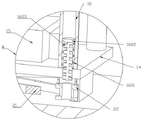
FIG. 6 is an enlarged view of the area A in FIG. 5 according to the present invention.
In the figure: 1-base, 2-support column, 3-upright column, 4-top plate, 401-fixing plate, 5-base, 6-motor, 7-gear, 8-rack, 801-step groove, 802-step block, 9-upper template, 10-upper mold core, 11-protective shell, 12-guide column, 13-vertical plate, 14-lower template, 1401-chute, 1402-sliding column, 15-lower mold core, 16-sleeve, 1601-reset spring, 1602-extrusion plate, 1603-screw, 17-clamping plate, 18-rotating plate, 19-connecting rod, 20-first belt pulley, 21-belt and 22-second belt pulley.
Detailed Description
The technical solutions in the embodiments of the present invention will be clearly and completely described below with reference to the drawings in the embodiments of the present invention, and it is obvious that the described embodiments are only a part of the embodiments of the present invention, and not all of the embodiments. All other embodiments, which can be derived by a person skilled in the art from the embodiments given herein without making any creative effort, shall fall within the protection scope of the present invention.
Referring to fig. 1-6, the present invention provides a technical solution: a press-fit die for a metal keyboard frame of a notebook computer comprises a base 1, wherein upright posts 3 are fixedly connected to the left side and the right side of the upper end surface of the base 1, a top plate 4 is fixedly connected to the upper end surface of each upright post 3, a machine base 5 is fixedly connected to the middle of the upper end surface of each top plate 4, a motor 6 is arranged on the upper end surface of each machine base 5, a gear 7 is fixedly connected to the output shaft end of each motor 6, a rack 8 is meshed and connected to the rear end of each gear 7, an upper template 9 is fixedly connected to the lower end surface of each rack 8, an upper die core 10 is arranged in the middle of the lower end surface of each upper template 9, guide posts 12 are fixedly connected to the outer side of the lower end surface of each upper template 9, a lower template 14 is fixedly connected to the middle of the upper end surface of each base 1 through a vertical plate 13, a sleeve 16 is fixedly connected to the outer side of the upper end surface of each lower template 14, a rotating plate 18 is rotatably connected to the middle of the lower end surface of each rotating plate 18, connecting rods 19 are rotatably connected to the left end surface and the left of each rotating plate, and the lower pulley 20 is fixedly connected to the end surface of each rotating plate 18, an inner cavity of the sleeve 16 on the right side of the front portion of the base 1 is provided with a return spring 1601, an upper end face of the return spring 1601 is fixedly connected with an extrusion plate 1602, and a lower end face of the extrusion plate 1602 is fixedly connected with a screw 1603.
In this embodiment, the lower end surface of the base 1 is provided with the support columns 2, and the lower end surface of each support column 2 is provided with the pad foot. The lower end face of the supporting column 2 is provided with the pad feet, so that the friction force between the whole device and the ground is increased, and the stability of the whole device in working is ensured.
In this embodiment, the inner cavity of the rack 8 is provided with a stepped groove 801 in a penetrating manner, the inner cavity of the stepped groove 801 is slidably connected with a stepped block 802, the middle part of the rear end face of the top plate 4 is fixedly connected with a fixing plate 401, and the fixing plate 401 is fixedly connected with the stepped block 802. The user makes gear 7 obtain rotating through starter motor 6, because gear 7 is connected with the meshing of rack 8, slides at the ladder groove 801 inner chamber at cooperation ladder piece 802 to rack 8 obtains rising or descends, and then cope match-plate pattern 9 obtains rising or descends, and the lower bolster 14 of deuterogamying, thereby whole device has realized the function of die.
In this embodiment, a protection shell 11 is disposed on the lower end surface of the upper template 9 and outside the upper mold core 10, a lower mold core 15 is disposed in the middle of the upper end surface of the lower template 14, and the diameter of the inner cavity of the sleeve 16 is equal to the diameter of the guide pillar 12. Through being provided with sleeve 16 and guide pillar 12, when cope match-plate pattern 9 carries out the die to lower bolster 14, improved the precision of die, through being provided with protecting crust 11, avoided whole device die subassembly spill when the die to injure the staff.
In this embodiment, the left and right sides of the lower end surface of the base 1 are provided with sliding chutes 1401, the inner cavity of the sliding chute 1401 is slidably connected with sliding columns 1402, the upper end surface of the sliding columns 1402 is fixedly connected with a clamping plate 17, the inner side wall of the clamping plate 17 is provided with a rubber pad, and the sliding columns 1402 are rotatably connected with the connecting rod 19. When the upper die plate 9 moves downwards, the guide post 12 moves downwards, when the guide post 12 moves downwards to a certain position, the guide post 12 can extrude the extrusion plate to enable the screw 1603 to move downwards, due to the fact that the screw 1603 is in threaded connection with the second belt pulley 22, the thread lead angle of the screw 1603 is larger than the equivalent friction angle of the second belt pulley 22, the second belt pulley 22 rotates and then is matched with the belt 21, the first belt pulley 20 rotates, the rotating plate 18 rotates, the sliding column 1402 slides in the inner cavity of the sliding groove 1401 through the rotating connection of the rotating plate 18 and the connecting rod 19, the sliding column 1402 moves towards the middle of the base 1, the clamping plate 17 can clamp the to-be-stamped component on the lower die core 15 in the middle, the phenomenon that the stamping die component splashes out when the upper die core 10 stamps on the lower die core 15 is avoided, and the safety of the whole device is further improved.
In this embodiment, the front right side of the lower end surface of the base 1 is rotatably connected with a second belt pulley 22 through a shaft sleeve, a belt 21 is arranged between the first belt pulley 20 and the second belt pulley 22, the screw 1603 is in penetrating connection with the base 1 and the sleeve 16, the screw 1603 is in threaded connection with the second belt pulley 22, and the lead angle of the screw 1603 is larger than the equivalent friction angle of the second belt pulley 22.
When the stamping device works, a user rotates the gear 7 by starting the motor 6, the gear 7 is meshed with the rack 8 and slides in the cavity of the stepped groove 801 in cooperation with the stepped block 802, so that the rack 8 is lifted or lowered, the upper template 9 is lifted or lowered, and then the lower template 14 is matched, so that the stamping device realizes the function of stamping, the stamping accuracy is improved when the upper template 9 stamps the lower template 14 by arranging the sleeve 16 and the guide post 12, the stamping device is prevented from being hurt to the worker by splashing of a stamping assembly when the whole stamping device stamps by arranging the protective shell 11, the guide post 12 moves downwards when the upper template 9 moves downwards, the guide post 12 can extrude the extrusion plate to enable the screw rod 1603 to move downwards when the guide post 12 moves downwards to a certain position, and the lead angle of the screw rod 1603 is larger than the equivalent friction angle of the second belt pulley 22 due to the threaded connection of the screw rod 1603 and the second belt pulley 22, thereby second belt pulley 22 obtains rotating, deuterogamy belt 21, thereby first belt pulley 20 obtains rotating, rotor plate 18 obtains rotating, it is connected with connecting rod 19 to rotate through rotor plate 18, traveller 1402 slides in spout 1401 inner chamber, thereby traveller 1402 removes to base 1 middle part, splint 17 can treat the centre gripping of die assembly in the middle part on lower mould benevolence 15, it spouts to go up die assembly when the punching press of lower mould benevolence 15 to have avoided last mould benevolence 10, the security of whole device has further been improved, all be provided with the pad foot through support column 2 lower extreme, the frictional force between whole device and ground has been increased, the stability of whole device at the during operation has been guaranteed. The whole press-fit die for the metal keyboard frame of the notebook computer avoids the workpiece from splashing to cause worker injury during punching through the matching of the clamping plate 17, the protective shell 11 and the like, and improves the safety of the whole device.
It is noted that, herein, relational terms such as first and second, and the like may be used solely to distinguish one entity or action from another entity or action without necessarily requiring or implying any actual such relationship or order between such entities or actions. Also, the terms "comprises," "comprising," or any other variation thereof, are intended to cover a non-exclusive inclusion, such that a process, method, article, or apparatus that comprises a list of elements does not include only those elements but may include other elements not expressly listed or inherent to such process, method, article, or apparatus. Without further limitation. The use of the phrase "comprising one of the elements does not exclude the presence of other like elements in the process, method, article, or apparatus that comprises the element.
Although embodiments of the present invention have been shown and described, it will be appreciated by those skilled in the art that changes, modifications, substitutions and alterations can be made in these embodiments without departing from the principles and spirit of the utility model, the scope of which is defined in the appended claims and their equivalents.
Claims (6)
1. The utility model provides a press fitting die utensil of notebook computer metal keyboard frame, includes base (1), its characterized in that: the left side and the right side of the upper end face of the base (1) are fixedly connected with upright columns (3), the upper end face of each upright column (3) is fixedly connected with a top plate (4), the middle part of the upper end face of each top plate (4) is fixedly connected with a machine base (5), the upper end face of each machine base (5) is provided with a motor (6), an output shaft end of each motor (6) is fixedly connected with a gear (7), the rear end of each gear (7) is meshed with a rack (8), the lower end face of each rack (8) is fixedly connected with an upper template (9), the middle part of the lower end face of each upper template (9) is provided with an upper mold core (10), the outer side of the lower end face of each upper template (9) is fixedly connected with a guide post (12), the middle part of the upper end face of the base (1) is fixedly connected with a lower template (14) through a vertical plate (13), and the outer side of the upper end face of the lower template (14) is fixedly connected with a sleeve (16), lower bolster (14) lower terminal surface middle part is rotated and is connected with rotor plate (18), both ends are rotated and are connected with connecting rod (19) about rotor plate (18) lower terminal surface, terminal surface fixedly connected with first belt pulley (20) under rotor plate (18), are located the anterior right side of base (1) sleeve (16) inner chamber is provided with reset spring (1601), reset spring (1601) up end fixedly connected with stripper plate (1602), terminal surface fixedly connected with screw rod (1603) under stripper plate (1602).
2. The press-fit die for the metal keyboard frame of the notebook computer according to claim 1, wherein: the lower end face of the base (1) is provided with support columns (2), and each support column (2) is provided with a pad foot on the lower end face.
3. The press-fit die for the metal keyboard frame of the notebook computer according to claim 1, wherein: rack (8) inner chamber runs through and is provided with ladder groove (801), ladder groove (801) inner chamber sliding connection has ladder piece (802), roof (4) rear end face middle part fixedly connected with fixed plate (401), fixed plate (401) and ladder piece (802) fixed connection.
4. The press-fit die for the metal keyboard frame of the notebook computer according to claim 1, wherein: the lower end face of the upper template (9) is positioned on the outer side of the upper die core (10) and is provided with a protective shell (11), the middle of the upper end face of the lower template (14) is provided with a lower die core (15), and the diameter of the inner cavity of the sleeve (16) is equal to that of the guide pillar (12).
5. The press-fit die for the metal keyboard frame of the notebook computer according to claim 1, wherein: the left side and the right side of the lower end face of the base (1) are provided with sliding grooves (1401), the inner cavity of each sliding groove (1401) is connected with a sliding column (1402) in a sliding mode, the upper end face of each sliding column (1402) is fixedly connected with a clamping plate (17), a rubber pad is arranged on the inner side wall of each clamping plate (17), and each sliding column (1402) is rotatably connected with a connecting rod (19).
6. The press-fit die for the metal keyboard frame of the notebook computer according to claim 1, wherein: base (1) lower terminal surface front portion right side is connected with second belt pulley (22) through the axle sleeve rotation, be provided with belt (21) between first belt pulley (20) and second belt pulley (22), screw rod (1603) and base (1), sleeve (16) through connection, screw rod (1603) and second belt pulley (22) threaded connection, the lead angle of screw rod (1603) is greater than second belt pulley (22) equivalent friction angle.
Priority Applications (1)
| Application Number | Priority Date | Filing Date | Title |
|---|---|---|---|
| CN202121379589.2U CN215355742U (en) | 2021-06-22 | 2021-06-22 | Pressing die for metal keyboard frame of notebook computer |
Applications Claiming Priority (1)
| Application Number | Priority Date | Filing Date | Title |
|---|---|---|---|
| CN202121379589.2U CN215355742U (en) | 2021-06-22 | 2021-06-22 | Pressing die for metal keyboard frame of notebook computer |
Publications (1)
| Publication Number | Publication Date |
|---|---|
| CN215355742U true CN215355742U (en) | 2021-12-31 |
Family
ID=79636052
Family Applications (1)
| Application Number | Title | Priority Date | Filing Date |
|---|---|---|---|
| CN202121379589.2U Active CN215355742U (en) | 2021-06-22 | 2021-06-22 | Pressing die for metal keyboard frame of notebook computer |
Country Status (1)
| Country | Link |
|---|---|
| CN (1) | CN215355742U (en) |
Cited By (1)
| Publication number | Priority date | Publication date | Assignee | Title |
|---|---|---|---|---|
| CN116037778A (en) * | 2023-01-06 | 2023-05-02 | 江苏科彦汽车配件有限公司 | Multi-station equal-height stretching tool die |
-
2021
- 2021-06-22 CN CN202121379589.2U patent/CN215355742U/en active Active
Cited By (2)
| Publication number | Priority date | Publication date | Assignee | Title |
|---|---|---|---|---|
| CN116037778A (en) * | 2023-01-06 | 2023-05-02 | 江苏科彦汽车配件有限公司 | Multi-station equal-height stretching tool die |
| CN116037778B (en) * | 2023-01-06 | 2023-09-26 | 江苏科彦汽车配件有限公司 | Multi-station equal-height stretching tool die |
Similar Documents
| Publication | Publication Date | Title |
|---|---|---|
| CN215355742U (en) | Pressing die for metal keyboard frame of notebook computer | |
| CN208084814U (en) | A kind of mold with elevating function | |
| CN210412186U (en) | Mould for forming mechanical parts | |
| CN215965722U (en) | Continuous type apron stamping device is used in lithium cell production and processing | |
| CN214820334U (en) | Auxiliary device is changed to car shift knob injection mold | |
| CN210632927U (en) | Casting device for silverware machining | |
| CN115722593A (en) | Stamping die for manufacturing automobile parts and using method thereof | |
| CN215150952U (en) | Adjustable PCB mould | |
| CN215544232U (en) | Stamping die of refrigerator chassis | |
| CN214872033U (en) | Adjustable precise mold positioning device | |
| CN210632828U (en) | Steel processing die capable of achieving rapid forming | |
| CN209969374U (en) | Automatic blanking hardware mould | |
| CN211330938U (en) | Car cut-out press locating component | |
| CN211440754U (en) | Automatic plastic mold of unloading | |
| CN208438531U (en) | A kind of sawdust pallet processing mold | |
| CN215965861U (en) | Bending and shaping die for automobile plate | |
| CN213290113U (en) | High-precision part die fixing device | |
| CN112692134A (en) | Automobile exhaust pipe stamping device | |
| CN213001966U (en) | Sheet metal stamping device that stamping precision is high | |
| CN213079690U (en) | High-precision automobile stamping die with safety protection device | |
| CN217986840U (en) | A quick punching press leveling device of sole for leather shoes production | |
| CN220216512U (en) | Production mould of electronic scale shell | |
| CN220497517U (en) | Automobile upright column mold with rapid demolding structure | |
| CN215703668U (en) | Casting mold for producing rapidly-shaped monocular | |
| CN214184939U (en) | Lamp frame aluminum profile machining die |
Legal Events
| Date | Code | Title | Description |
|---|---|---|---|
| GR01 | Patent grant | ||
| GR01 | Patent grant |