CN215278783U - Surface cleaning device for metal galvanizing - Google Patents
Surface cleaning device for metal galvanizing Download PDFInfo
- Publication number
- CN215278783U CN215278783U CN202120847047.7U CN202120847047U CN215278783U CN 215278783 U CN215278783 U CN 215278783U CN 202120847047 U CN202120847047 U CN 202120847047U CN 215278783 U CN215278783 U CN 215278783U
- Authority
- CN
- China
- Prior art keywords
- main body
- support
- servo motor
- surface cleaning
- plc controller
- Prior art date
- Legal status (The legal status is an assumption and is not a legal conclusion. Google has not performed a legal analysis and makes no representation as to the accuracy of the status listed.)
- Active
Links
Images


Abstract
The utility model discloses a surface cleaning device for metal galvanizing relates to metal galvanizing processing technology field, which comprises a bracket and a main body, the landing leg is all installed to four corners of main part bottom, the central point department on the inside top of main part installs the water collector, and the bottom of water collector installs the collecting pipe, the filter box is installed to the central point department of main part bottom, the bottom of collecting pipe runs through main part and filter box and extends to the inside of filter box, the filter screen is installed to the inside central point department of filter box. The utility model discloses a place the board and drive the kicking block and to the inside removal of support, give the PLC controller with the signal transmission when the kicking block touches pressure sensor, step motor starts to drive the baffle downstream through the gear this moment, and the shower nozzle is outside to spray water simultaneously, so not only can the water economy resource, can also prevent that the splash from splashing to the device outside when abluent simultaneously.
Description
Technical Field
The utility model relates to a metal galvanization processing technology field specifically is a surface cleaning device for metal galvanization.
Background
Galvanization refers to a surface treatment technology for plating a layer of zinc on the surface of metal, alloy or other materials to play the roles of beauty, rust prevention and the like, and after galvanization of the metal is completed, the metal needs to be cleaned, and the existing surface cleaning device for galvanization of the metal has certain defects.
Through retrieval, chinese patent No. CN110252705A, published 2019, 09.20, the publication proposes that "the bottom of the inner wall of the cleaning box is fixedly connected with a cylinder, a piston end of the cylinder is fixedly connected with a support plate, a top of the support plate is fixedly connected with a placing net, and a top of the cleaning box is provided with a cleaning cover", the device cannot automatically induce water, and needs to use a large amount of water for cleaning.
SUMMERY OF THE UTILITY MODEL
An object of the utility model is to provide a metal is surface cleaning device for zinc-plating to it can cause the extravagant problem of water resources to propose the unable auto-induction of current device and go out water among the above-mentioned background art to solve.
In order to achieve the above object, the utility model provides a following technical scheme: a surface cleaning device for metal galvanizing comprises a bracket and a main body, and also comprises a taking structure which is convenient for taking and placing materials, an adjusting structure which can clean metals with different shapes and a water-saving structure which can prevent spray splashing;
the bottom end of the main body is provided with a drain pipe, one side of one end of the main body, which is close to the drain pipe, is provided with a PLC (programmable logic controller), and the taking structure is arranged on one side of the main body, which is far away from the PLC;
the top end of the main body is provided with a placing plate through a sliding block, a bracket is arranged in the middle of the top end of the main body, and the adjusting structure is arranged in the middle of the front end and the rear end of the bracket;
the utility model discloses a water conservation structure, including support, water conservation structure, PLC controller, water inlet pipe, a plurality of shower nozzles, water conservation structure and water conservation structure, the central point department on support top installs the inlet tube, a plurality of shower nozzles are installed to the top of support inside equidistant, the water conservation structure sets up in one side that the PLC controller was kept away from on the support top.
Preferably, the water-saving structure is still including the box, the box sets up in one side that the PLC controller was kept away from on the support top, step motor is installed to the inside one end of box, and step motor's output installs the gear, the baffle is installed to one side that the PLC controller was kept away from to the support, and the top of baffle runs through the box and extends to the outside of box, place the board and install the kicking block near one side of PLC controller, the inside bottom that is close to PLC controller one side of support is installed pressure sensor.
Preferably, a rack is arranged at the middle position of the baffle close to the bracket once, and the baffle is meshed with the gear.
Preferably, the placing plate is connected with the main body in a sliding mode, and the placing plate is in a grid shape.
Preferably, get and take the structure and constitute by thread bush, lead screw, fixed plate, first servo motor and horizontal pole, the fixed plate sets up in the main part and keeps away from the bottom of PLC controller one side, first servo motor is installed to one side of fixed plate, the central point department that the main part is close to fixed plate one side installs the lead screw through the bearing, first servo motor's output runs through the fixed plate through the pivot and is connected with the lead screw, the outer wall cover of lead screw one end is equipped with the thread bush, and first servo motor installs the horizontal pole near the top of main part one side.
Preferably, adjust the structure by turn round, baffle, sponge piece, first screw thread piece, first screw rod, second servo motor and second screw thread piece and constitute, first screw thread piece sets up in the central point department of support both sides, the inside of first screw thread piece all is provided with first screw rod, and the one end that the support was kept away from to first screw rod all runs through first screw thread piece and installs the turn round, the other end of first screw rod all runs through first screw thread piece and support mounting has the baffle, and the baffle top all installs second servo motor near one side of PLC controller, the second screw rod is all installed through the bearing in the inside top of baffle, and the outer wall cover of second screw rod all is equipped with second screw thread piece, the one end that the support was kept away from to second screw thread piece all runs through the baffle and installs the sponge piece.
Preferably, the length of the sponge block is the same as that of the partition plate, and the front view shape of the sponge block is a long strip.
Compared with the prior art, the beneficial effects of the utility model are that:
1. the utility model provides a place the board, the box, the baffle, the gear, the PLC controller, step motor, kicking block and pressure sensor, utilize and place the board and drive the kicking block and move to support inside, when the kicking block touches pressure sensor, pressure sensor transmits the signal to the PLC controller this moment, step motor starts to drive gear revolve this moment, then the gear drives the baffle and moves down, PLC controller control shower nozzle outwards sprays water simultaneously, so not only can the water resource be saved, can also prevent that the splash from to the device outside when wasing simultaneously, influence operational environment, the problem of water waste has been solved;
2. the utility model provides a threaded sleeve, a screw rod, a fixed plate, a first servo motor and a cross rod, the material is prevented at the top of a placing plate by utilizing the threaded sleeve, at the moment, the first servo motor drives the screw rod to rotate, so that the threaded sleeve pushes the placing plate to move through the cross rod, the material can be conveniently prevented from being cleaned and taken out in the support, and the problem of taking the material is solved;
3. the utility model provides a have the turn round, a baffle, the sponge piece, first screw thread piece, first screw rod, the second screw rod, second servo motor and second screw thread piece, it is rotatory to utilize to rotate the turn round to drive first screw rod for the baffle presss from both sides tight material both sides, drives the second screw rod through second servo motor afterwards and rotates, makes second screw thread piece drive the sponge piece and removes in the both sides of device, thereby washs the both sides of device, has solved the problem of not equidimension metal clearance difficulty.
Drawings
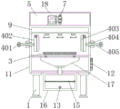
Fig. 1 is a schematic view of the front cross-sectional structure of the present invention;
FIG. 2 is a schematic side view of the cross-sectional structure of the present invention;
FIG. 3 is a schematic top view of the cross-sectional structure of the present invention;
FIG. 4 is an enlarged schematic view of the structure A in FIG. 1 according to the present invention;
fig. 5 is an enlarged schematic structural diagram of B in fig. 3 according to the present invention.
In the figure: 1. a support leg; 2. a taking structure; 201. a threaded sleeve; 202. a screw rod; 203. a fixing plate; 204. a first servo motor; 205. a cross bar; 3. placing the plate; 4. an adjustment structure; 401. turning the head; 402. a partition plate; 403. a sponge block; 404. a first thread block; 405. a first screw; 406. a second screw; 407. a second servo motor; 408. a second thread block; 5. a box body; 6. a baffle plate; 7. a gear; 8. a water inlet pipe; 9. a support; 10. a spray head; 11. a main body; 12. a PLC controller; 13. a drain pipe; 14. a collection pipe; 15. a filter screen; 16. a filter box; 17. a water collector; 18. a stepping motor; 19. a top block; 20. a pressure sensor.
Detailed Description
The technical solutions in the embodiments of the present invention will be described clearly and completely with reference to the accompanying drawings in the embodiments of the present invention, and it is obvious that the described embodiments are only some embodiments of the present invention, not all embodiments. Based on the embodiments in the present invention, all other embodiments obtained by a person skilled in the art without creative work belong to the protection scope of the present invention.
Example 1: referring to fig. 1-5, a surface cleaning device for metal galvanizing comprises a bracket 9 and a main body 11, and further comprises a taking structure 2 for conveniently taking and placing materials, an adjusting structure 4 for cleaning metals with different shapes and a water-saving structure for preventing splash;
the supporting legs 1 are mounted at four corners of the bottom end of the main body 11, a water collector 17 is mounted at the central position of the top end inside the main body 11, a collecting pipe 14 is mounted at the bottom end of the water collector 17, a filter box 16 is mounted at the central position of the bottom end of the main body 11, the bottom end of the collecting pipe 14 penetrates through the main body 11 and the filter box 16 and extends into the filter box 16, a filter screen 15 is mounted at the central position inside the filter box 16, a drain pipe 13 is mounted at the bottom end of one side of the filter box 16, a PLC (programmable logic controller) 12 is mounted at one side, close to the drain pipe 13, of one end of the main body 11, the PLC 12 can be in a FHR-211 type, and the taking structure 2 is arranged at one side, far away from the PLC 12, of the main body 11;
the top end of the main body 11 is provided with the placing plate 3 through a sliding block, the middle position of the top end of the main body 11 is provided with the bracket 9, and the adjusting structure 4 is arranged at the central position of the front end and the rear end of the bracket 9;
a water inlet pipe 8 is arranged at the center of the top end of the bracket 9, a plurality of spray heads 10 are arranged at equal intervals at the top end inside the bracket 9, and a water-saving structure is arranged at one side of the top end of the bracket 9 far away from the PLC 12;
referring to fig. 1-5, the surface cleaning device for metal galvanizing further comprises a water saving structure, the water saving structure comprises a box body 5, the box body 5 is arranged on one side, away from a PLC controller 12, of the top end of a support 9, a stepping motor 18 is arranged at one end inside the box body 5, a gear 7 is arranged at the output end of the stepping motor 18, a baffle 6 is arranged on one side, away from the PLC controller 12, of the support 9, the top end of the baffle 6 penetrates through the box body 5 and extends to the outside of the box body 5, a top block 19 is arranged on one side, close to the PLC controller 12, of a placing plate 3, and a pressure sensor 20 is arranged at the bottom end, close to the PLC controller 12, inside the support 9;
a rack is arranged at the middle position of the baffle 6 close to the bracket 9 once, and the baffle 6 is meshed with the gear 7;
the placing plate 3 is connected with the main body 11 in a sliding way, and the placing plate 3 is in a grid shape;
specifically, as shown in fig. 1, fig. 2, and fig. 4, top block 19 is driven to move towards the inside of support 9 by placing plate 3, when top block 19 touches pressure sensor 20, the model of this pressure sensor 20 can be XM-C14, pressure sensor 20 gives PLC controller 12 with signal transmission this moment, PLC controller 12 controls step motor 18 to start and drives gear 7 and rotate, the model of this step motor 18 can be 57BYG250B, gear 7 drives baffle 6 and moves down afterwards, PLC controller 12 controls shower nozzle 10 and outwards sprays water simultaneously, so not only can the water economy resource, can also prevent that the splash from to the device outside in abluent time simultaneously, influence operational environment.
Example 2: the taking structure 2 comprises a threaded sleeve 201, a screw rod 202, a fixing plate 203, a first servo motor 204 and a cross rod 205, the fixing plate 203 is arranged at the bottom end of one side of the main body 11, which is far away from the PLC 12, the first servo motor 204 is arranged at one side of the fixing plate 203, the screw rod 202 is arranged at the central position of one side of the main body 11, which is close to the fixing plate 203, through a bearing, the output end of the first servo motor 204 penetrates through the fixing plate 203 through a rotating shaft to be connected with the screw rod 202, the threaded sleeve 201 is sleeved on the outer wall of one end of the screw rod 202, and the cross rod 205 is arranged above one side of the first servo motor 204, which is close to the main body 11;
specifically, as shown in fig. 1 and fig. 2, the PLC controller 12 controls the first servo motor 204 to start, the model of the first servo motor 204 may be 130N-LM 06025S, and then the material is prevented from being placed on the top of the placing plate 3, at this time, the first servo motor 204 drives the screw rod 202 to rotate, so that the thread sleeve 201 pushes the placing plate 3 to move through the cross rod 205, and thus, the material can be conveniently prevented from being cleaned and taken out inside the bracket 9.
Example 3: the adjusting structure 4 comprises a rotary head 401, a partition plate 402, a sponge block 403, a first thread block 404, a first screw 405, a second screw 406, a second servo motor 407 and a second thread block 408, wherein the first thread block 404 is arranged at the central position of two sides of the bracket 9, the first screw 405 is arranged inside the first thread block 404, one end of the first screw 405, far away from the bracket 9, penetrates through the first thread block 404 and is provided with the rotary head 401, the other end of the first screw 405 penetrates through the first thread block 404 and the bracket 9 and is provided with the partition plate 402, one side, close to the PLC controller 12, of the top end of the partition plate 402 is provided with the second servo motor 407, the top end inside the partition plate 402 is provided with the second screw 406 through a bearing, the outer wall of the second screw 406 is sleeved with the second thread block 408, and one end, far away from the bracket 9, of the second thread block 408 penetrates through the partition plate 402 and is provided with the sponge block 403;
the length of the sponge block 403 is the same as that of the partition board 402, and the sponge block 403 is in a long strip shape in front view
Specifically, as shown in fig. 1, 2, 3 and 5, the rotor 401 is rotated to drive the first screw 405 to rotate, so that the partition 402 clamps two sides of the material, and then the PLC controller 12 controls the second servo motor 407 to start, the type of the second servo motor 407 may be HC-KFS 23, at this time, the second servo motor 407 drives the second screw 406 to rotate, so that the second screw 408 drives the sponge block 403 to move on two sides of the device, thereby cleaning two sides of the device.
The output end of the PLC controller 12 is electrically connected to the input ends of the first servo motor 204, the second servo motor 407 and the stepping motor 18 through wires, and the input end of the PLC controller 12 is electrically connected to the output end of the pressure sensor 20.
The working principle is as follows: when the device is used, firstly, the device is electrified, and then, materials to be cleaned are placed at the top end of the placing plate 3;
the first innovation point implementation step:
the first step is as follows: the PLC controller 12 controls the first servo motor 204 to start;
the second step is that: the first servo motor 204 drives the screw rod 202 to rotate;
a third part: the threaded sleeve 201 pushes the placing plate 3 to move through the cross rod 205.
The implementation step of the second innovation point:
the first step is as follows: the placing plate 3 drives the top block 19 to move towards the inside of the bracket 9;
the second step is that: when the top block 19 touches the pressure sensor 20, the pressure sensor 20 transmits a signal to the PLC 12;
the third step: the PLC 12 controls the stepping motor 18 to start to drive the gear 7 to move, then the gear 7 drives the baffle 6 to move downwards, and meanwhile the PLC 12 controls the spray head 10 to spray water outwards.
The third innovation point implementation step:
the first step is as follows: the rotating head 401 is rotated to drive the first screw 405 to rotate, so that the partition plate 402 clamps two sides of the material;
the second step is that: the second servo motor 407 is controlled to start by the PLC controller 12;
the third step: the second screw 406 is rotated by the second servo motor 407, so that the second screw block 408 drives the sponge block 403 to move on both sides of the device.
At this time, the apparatus cleans the metal, and the flow of cleaned water passes through the water collector 17, passes through the collecting pipe 14, flows into the filter box 16, is filtered by the filter screen 15, and is discharged to the outside of the apparatus through the drain pipe 13.
It is noted that, herein, relational terms such as first and second, and the like may be used solely to distinguish one entity or action from another entity or action without necessarily requiring or implying any actual such relationship or order between such entities or actions. Also, the terms "comprises," "comprising," or any other variation thereof, are intended to cover a non-exclusive inclusion, such that a process, method, article, or apparatus that comprises a list of elements does not include only those elements but may include other elements not expressly listed or inherent to such process, method, article, or apparatus.
Although embodiments of the present invention have been shown and described, it will be appreciated by those skilled in the art that changes, modifications, substitutions and alterations can be made in these embodiments without departing from the principles and spirit of the invention, the scope of which is defined in the appended claims and their equivalents.
Claims (7)
1. A surface cleaning device for metal galvanizing comprises a bracket (9) and a main body (11), and is characterized in that: the device also comprises a taking structure (2) which is convenient for taking and placing materials, an adjusting structure (4) which can clean metals with different shapes and a water-saving structure which can prevent spray splashing;
the supporting legs (1) are mounted at four corners of the bottom end of the main body (11), a water collector (17) is mounted at the central position of the top end inside the main body (11), a collecting pipe (14) is mounted at the bottom end of the water collector (17), a filter box (16) is mounted at the central position of the bottom end of the main body (11), the bottom end of the collecting pipe (14) penetrates through the main body (11) and the filter box (16) and extends to the inside of the filter box (16), a filter screen (15) is mounted at the central position inside the filter box (16), a drain pipe (13) is mounted at the bottom end of one side of the filter box (16), a PLC (12) is mounted at one side, close to the drain pipe (13), of one end of the main body (11), and the taking structure (2) is arranged at one side, far away from the PLC (12), of the main body (11);
the top end of the main body (11) is provided with a placing plate (3) through a sliding block, the middle position of the top end of the main body (11) is provided with a bracket (9), and the adjusting structure (4) is arranged at the central position of the front end and the rear end of the bracket (9);
the utility model discloses a water conservation structure, including support (9), water conservation structure, water inlet pipe (8) are installed to the central point department on support (9) top, a plurality of shower nozzles (10) are installed to the top of support (9) inside equidistant, the water conservation structure sets up in one side of keeping away from PLC controller (12) on support (9) top.
2. The surface cleaning apparatus for galvanizing metals according to claim 1, wherein: the water-saving structure is characterized by further comprising a box body (5), the box body (5) is arranged on one side, away from the PLC controller (12), of the top end of the support (9), the step motor (18) is installed at one end of the inside of the box body (5), the gear (7) is installed at the output end of the step motor (18), the baffle (6) is installed on one side, away from the PLC controller (12), of the support (9), the top end of the baffle (6) penetrates through the box body (5) and extends to the outside of the box body (5), one side, close to the PLC controller (12), of the placing plate (3) is provided with a top block (19), and the bottom, close to one side of the PLC controller (12), of the inside of the support (9) is provided with a pressure sensor (20).
3. The surface cleaning apparatus for galvanizing metal according to claim 2, wherein: the baffle (6) is provided with a rack at the middle position close to the bracket (9) once, and the baffle (6) is meshed with the gear (7).
4. The surface cleaning apparatus for galvanizing metals according to claim 1, wherein: the placing plate (3) is in sliding connection with the main body (11), and the placing plate (3) is in a grid shape.
5. The surface cleaning apparatus for galvanizing metals according to claim 1, wherein: get and take structure (2) and constitute by thread bush (201), lead screw (202), fixed plate (203), first servo motor (204) and horizontal pole (205), fixed plate (203) set up in main part (11) and keep away from the bottom of PLC controller (12) one side, first servo motor (204) are installed to one side of fixed plate (203), main part (11) are close to central point department of fixed plate (203) one side and install lead screw (202) through the bearing, the output of first servo motor (204) runs through fixed plate (203) through the pivot and is connected with lead screw (202), the outer wall cover of lead screw (202) one end is equipped with thread bush (201), and horizontal pole (205) are installed to the top that first servo motor (204) are close to main part (11) one side.
6. The surface cleaning apparatus for galvanizing metals according to claim 1, wherein: the adjusting structure (4) is composed of a rotating head (401), a partition plate (402), a sponge block (403), a first thread block (404), a first screw rod (405), a second screw rod (406), a second servo motor (407) and a second thread block (408), the first thread block (404) is arranged at the central position of two sides of the support (9), the first screw rod (405) is arranged inside the first thread block (404), one end, far away from the support (9), of the first screw rod (405) penetrates through the first thread block (404) to be provided with the rotating head (401), the other end of the first screw rod (405) penetrates through the first thread block (404) and the support (9) to be provided with the partition plate (402), the second servo motor (407) is arranged on one side, close to the PLC (12), of the top end of the top of the partition plate (402) is provided with the second screw rod (406) through a bearing, and the outer wall sleeve of the second screw (406) is provided with a second thread block (408), and one end of the second thread block (408) far away from the bracket (9) penetrates through the partition plate (402) and is provided with a sponge block (403).
7. The surface cleaning apparatus for galvanizing metal according to claim 6, wherein: the length of the sponge block (403) is the same as that of the partition board (402), and the front view shape of the sponge block (403) is a long strip.
Priority Applications (1)
| Application Number | Priority Date | Filing Date | Title |
|---|---|---|---|
| CN202120847047.7U CN215278783U (en) | 2021-04-23 | 2021-04-23 | Surface cleaning device for metal galvanizing |
Applications Claiming Priority (1)
| Application Number | Priority Date | Filing Date | Title |
|---|---|---|---|
| CN202120847047.7U CN215278783U (en) | 2021-04-23 | 2021-04-23 | Surface cleaning device for metal galvanizing |
Publications (1)
| Publication Number | Publication Date |
|---|---|
| CN215278783U true CN215278783U (en) | 2021-12-24 |
Family
ID=79537867
Family Applications (1)
| Application Number | Title | Priority Date | Filing Date |
|---|---|---|---|
| CN202120847047.7U Active CN215278783U (en) | 2021-04-23 | 2021-04-23 | Surface cleaning device for metal galvanizing |
Country Status (1)
| Country | Link |
|---|---|
| CN (1) | CN215278783U (en) |
-
2021
- 2021-04-23 CN CN202120847047.7U patent/CN215278783U/en active Active
Similar Documents
| Publication | Publication Date | Title |
|---|---|---|
| CN105401627B (en) | Squatting pan intelligent washing and cleaning device | |
| CN112275706B (en) | Cleaning equipment is used in precision bearing production | |
| CN109124456A (en) | A kind of windowpane cleans the device of glass automatically | |
| CN209772899U (en) | Metal plate plating part cleaning and drying device for electroplating equipment | |
| CN215278783U (en) | Surface cleaning device for metal galvanizing | |
| CN208695742U (en) | A kind of Furniture panel cleaning device | |
| CN108819914B (en) | Closed integral cleaning equipment for automobile | |
| CN213134113U (en) | Dust collector is used in production of plastic-steel door and window | |
| CN216297254U (en) | Waste aluminum recovery pretreatment device | |
| CN215166936U (en) | Automatic energy-conserving building photovoltaic curtain wall of cleaning | |
| CN215613529U (en) | Belt cleaning device for copper is painted | |
| CN211322964U (en) | Inulin processingequipment | |
| CN211726690U (en) | Cleaning equipment for punching machining of bearing bush | |
| CN110102115B (en) | Air curtain machine cleaning device | |
| CN208928674U (en) | A kind of Chinese medicine cleaning equipment | |
| CN108489118B (en) | Device for automatically cleaning heat collecting pipe of solar water heater in rainy days | |
| CN111389783A (en) | Metal surface electroplating pretreatment device | |
| CN217474251U (en) | Tapered roller production is with seal structure's belt cleaning device | |
| CN210207802U (en) | Electrogalvanizing material belt cleaning device | |
| CN216262136U (en) | Precision positioning T-shaped nut integrated forming device | |
| CN220191997U (en) | Slaughter belt cleaning device | |
| CN215876407U (en) | Water body filtering structure for water supply and drainage for landscape | |
| CN220440658U (en) | From collection rain photovoltaic board cleaning device and control system thereof | |
| CN216585144U (en) | Sponge copper production soaks dissolving tank with easily wasing raw materials | |
| CN217099920U (en) | Novel vehicle flushing device arranged on supporting bridge plate |
Legal Events
| Date | Code | Title | Description |
|---|---|---|---|
| GR01 | Patent grant | ||
| GR01 | Patent grant |