SUMMERY OF THE UTILITY MODEL
In view of this, the utility model aims at overcoming the not enough among the prior art, provide a detect glass curtain wall's device.
The utility model provides a following technical scheme:
the embodiment of the utility model provides a detect glass curtain wall's device, include: the device comprises a wall climbing robot, a first connecting rod, a second connecting rod, an excitation device and a vibration pickup device; one end of the first connecting rod is connected with the wall climbing robot, and the other end of the first connecting rod is connected with the exciting device; one end of the second connecting rod is connected with the wall climbing robot, and the other end of the second connecting rod is connected with the vibration pickup device.
In a specific embodiment, the first connecting rod and the second connecting rod are both telescopic rods.
In a specific embodiment, one end of the first connecting rod is rotatably connected with the wall climbing robot and/or one end of the second connecting rod is rotatably connected with the wall climbing robot.
In a specific embodiment, the method further comprises the following steps: a first rotating mechanism and a second rotating mechanism; the fixed end of the first rotating mechanism is arranged on the wall climbing robot, and the rotating end of the first rotating mechanism is connected with one end of the first connecting rod;
the fixed end of the second rotating mechanism is arranged on the wall climbing robot, and the rotating end of the second rotating mechanism is connected with one end of the second connecting rod.
In a specific embodiment, the excitation device comprises: a drive assembly and a vibration source; wherein, the drive assembly is connected with the vibration source to drive the vibration source to vibrate.
In a particular embodiment, the drive assembly comprises: a sine wave signal generator with adjustable frequency and power and an electromagnetic exciting coil; the vibration source includes: an eccentric mass block; the eccentric mass block is connected with the electromagnetic excitation coil, the sine wave signal generator is connected with the electromagnetic excitation coil, and the electromagnetic excitation coil is controlled to drive the eccentric mass block to generate periodic vibration through signals generated by the sine wave signal generator.
In a specific embodiment, the excitation device further comprises: the distance adjusting module and the elastic layer are arranged on the base; the driving assembly is connected with the elastic layer and the elastic layer is connected with the distance adjusting module, and the distance adjusting module is connected with the first connecting rod so as to adjust the distance between the driving assembly and the first connecting rod through the distance adjusting module.
In a specific embodiment, the vibration pickup device comprises: an acceleration sensor.
In a specific embodiment, the vibration pickup device further comprises: a distance adjustment assembly; the acceleration sensor is connected with the second connecting rod through the distance adjusting assembly, so that the distance between the acceleration sensor and the second connecting rod is adjusted through the distance adjusting assembly.
In a specific embodiment, the method further comprises the following steps: a hauling rope; wherein, the haulage rope is connected the wall climbing robot.
The embodiment of the utility model has the following advantage:
the embodiment of the utility model provides a detect glass curtain wall's device, include: the device comprises a wall climbing robot, a first connecting rod, a second connecting rod, an excitation device and a vibration pickup device; one end of the first connecting rod is connected with the wall climbing robot, and the other end of the first connecting rod is connected with the exciting device; one end of the second connecting rod is connected with the wall climbing robot, and the other end of the second connecting rod is connected with the vibration pickup device. This scheme compares in current artifical detection mode, can measure under the environment on the spot, need not dismantle glass, and glass's operating condition is unanimous with the detection state, does benefit to the precision that improves the detection, and efficiency is very high, can realize the measurement of each position on the glass curtain wall.
In order to make the aforementioned and other objects, features and advantages of the present invention more comprehensible, preferred embodiments accompanied with figures are described in detail below.
Detailed Description
Reference will now be made in detail to embodiments of the present invention, examples of which are illustrated in the accompanying drawings, wherein like reference numerals refer to the same or similar elements or elements having the same or similar function throughout. The embodiments described below with reference to the drawings are exemplary only for the purpose of explaining the present invention, and should not be construed as limiting the present invention.
It will be understood that when an element is referred to as being "secured to" another element, it can be directly on the other element or intervening elements may also be present. When an element is referred to as being "connected" to another element, it can be directly connected to the other element or intervening elements may also be present. In contrast, when an element is referred to as being "directly on" another element, there are no intervening elements present. The terms "vertical," "horizontal," "left," "right," and the like as used herein are for illustrative purposes only.
In the present invention, unless otherwise expressly stated or limited, the terms "mounted," "connected," and "fixed" are to be construed broadly and may, for example, be fixedly connected, detachably connected, or integrally formed; can be mechanically or electrically connected; either directly or indirectly through intervening media, either internally or in any other relationship. The specific meaning of the above terms in the present invention can be understood according to specific situations by those skilled in the art.
Furthermore, the terms "first", "second" and "first" are used for descriptive purposes only and are not to be construed as indicating or implying relative importance or implicitly indicating the number of technical features indicated. Thus, a feature defined as "first" or "second" may explicitly or implicitly include one or more of that feature. In the description of the present invention, "a plurality" means two or more unless specifically limited otherwise.
Unless defined otherwise, all technical and scientific terms used herein have the same meaning as commonly understood by one of ordinary skill in the art to which this application belongs. The terminology used in the description of the templates herein is for the purpose of describing particular embodiments only and is not intended to be limiting of the invention. As used herein, the term "and/or" includes any and all combinations of one or more of the associated listed items.
Example 1
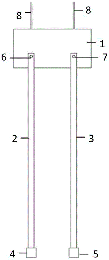
Embodiment 1 of the utility model discloses detect glass curtain wall's device, as shown in fig. 1 and fig. 2, include: the wall climbing robot comprises a wall climbing robot 1, a first connecting rod 2, a second connecting rod 3, an excitation device 4 and a vibration pickup device 5; one end of the first connecting rod 2 is connected with the wall-climbing robot 1, and the other end of the first connecting rod is connected with the exciting device 4; one end of the second connecting rod 3 is connected with the wall-climbing robot 1, and the other end is connected with the vibration pickup device 5.
Specifically, the wall-climbing robot 1 in this scheme may be an existing cleaning robot for a glass curtain wall, and has the capability of being fixed on the glass curtain wall and moving on the glass curtain wall, and specifically, for example, may be adsorbed on the glass curtain wall.
With the help of the removal of climbing robot 1, can drive head rod 2 and the second connecting rod 3 of connection on climbing robot 1, and finally drive the excitation device 4 of connection on head rod 2 and remove, and drive the device 5 removal of shaking of picking up of connection on second connecting rod 3, thus, through the device in this scheme, can move the position that needs the glass curtain wall that detects and detect, the state that detects is exactly the operating condition of glass curtain wall itself, realized detecting on the spot, and do benefit to the precision that improves the detection, compare in the general manual detection mode of curtain, can measure under the environment on the spot, need not dismantle glass, glass's operating condition is unanimous with the detection state, do benefit to the precision that improves the detection, and efficiency is very high, can realize the measurement of each position on the glass curtain wall.
In order to solve the problems that time and labor are not saved and errors are reduced in the conventional building specification and scientific research on the modal detection of the glass curtain wall, the counter sense is fully applied to mature structural dynamics and related knowledge of building structure health monitoring, and the method is characterized by simple structure, small volume and light weight, and can more accurately obtain the first-order natural frequency of the glass curtain wall. In addition, the method is simple to operate, high in repeatability and more suitable for engineering detection. Rely on ripe wall climbing robot 1 as the platform, connect excitation device 4 and pick up device 5 that shakes through the dead lever, both made things convenient for work and realized also that it is controllable to the position of excitation point and pick up the point of shaking.
Further, as shown in fig. 3, the first connecting rod 2 and the second connecting rod 3 are both telescopic rods.
Therefore, the first connecting rod 2 and the second connecting rod 3 are both provided with telescopic rods, and the positions of the excitation device 4 and the vibration pickup device 5 can be further adjusted, so that the vibration pickup device is suitable for more detection positions.
In addition, in order to reduce the weight of the first connecting rod 2 and the second connecting rod 3, specifically, the first connecting rod 2 and the second connecting rod 3 may be light steel telescopic rods, the telescopic length may be 600mm to 2000mm, and the like, and the specific telescopic length may be flexibly adjusted according to actual conditions.
Specifically, the lengths of the two connecting rods can be the same, and the structures can also be the same.
In a specific embodiment, the cross-section of the first connecting rod 2 and the second connecting rod 3 is circular or rectangular.
Specifically, the first connecting rod 2 and the second connecting rod 3 may be a square tube or a circular tube, or one may be a square tube and the other may be a circular tube.
Taking a square tube as an example, the telescopic square steel tube may be composed of three segments, for example, each segment is 700mm in length, the sections are respectively 50 × 50, 55 × 55, 60 × 60 notched light square steel tubes, and the thickness of the steel tubes is 2.5 mm. The overlapping position of the two steel pipes is 50 mm. Because the first connecting rod and the second connecting rod 3 have enough rigidity, the wall climbing robot is ensured not to be easily deformed, is light as much as possible, and reduces the load of the wall climbing robot 1.
Further, the first connecting rod 2 and the second connecting rod 3 are hollow inside and used for arranging wires of cables such as conducting wires and data wires.
Further, as shown in fig. 1 and 2, one end of the first connecting rod 2 is rotatably connected to the wall-climbing robot 1 and/or one end of the second connecting rod 3 is rotatably connected to the wall-climbing robot 1.
Specifically, the two ends of the first connecting rod 2 and the second connecting rod 3 can be both rotatably connected with the wall-climbing robot 1, and only one of the first connecting rod 2 and the second connecting rod 3 can be rotatably connected with the wall-climbing robot 1.
In a specific embodiment, the method further comprises the following steps: a first rotating mechanism 6 and a second rotating mechanism 7; the fixed end of the first rotating mechanism 6 is arranged on the wall-climbing robot 1, and the rotating end of the first rotating mechanism 6 is connected with one end of the first connecting rod 2;
the fixed end of the second rotating mechanism 7 is arranged on the wall-climbing robot 1, and the rotating end of the second rotating mechanism 7 is connected with one end of the second connecting rod 3.
Specifically, the first rotating mechanism 6 and the second rotating mechanism 7 may be motors, an output shaft of one of the motors is connected to the first connecting rod 2, and an output shaft of the other of the motors is connected to the second connecting rod 3, so that the first connecting rod 2 and the second connecting rod 3 can be driven to rotate.
Specifically, the first rotating mechanism 6 and the second rotating mechanism 7 can be bearings with a locking function, and when the bearings rotate to a certain angle, the bearings can be fixed at the bottom of the intersection through the locking function while realizing the angle rotation.
Specifically, first rotary mechanism 6, second rotary mechanism 7 can also be the bearing, and can also be provided with the threaded connection hole on head rod 2 and the second connecting rod 3, when head rod 2 and/or second connecting rod 3 rotated certain angle, can screw the threaded connection hole through the threaded rod until the threaded rod hugs closely on climbing robot 1, realize the angle of head rod 2 and second connecting rod 3 fixed.
Further, as shown in fig. 4, the excitation device 4 includes a driving assembly 41 and a vibration source 42; wherein, the driving component 41 is connected to the vibration source 42 to drive the vibration source 42 to vibrate.
Specifically, the driving assembly 41 includes: a sine wave signal generator with adjustable frequency and power and an electromagnetic exciting coil; the vibration source 42 includes: an eccentric mass block; the eccentric mass block is connected with the electromagnetic excitation coil, the sine wave signal generator is connected with the electromagnetic excitation coil, and the electromagnetic excitation coil is controlled to drive the eccentric mass block to generate periodic vibration through signals generated by the sine wave signal generator.
According to researches, the first-order natural frequency of a common glass curtain wall is concentrated on 40-200 HZ, the electromagnetic excitation coil is connected to the sine wave signal generator with adjustable frequency and adjustable power, the frequency can be adjusted in the range, the voltage of the sine wave signal generator is in a safe range, and based on the voltage, the signal generated by the sine wave signal generator can control the electromagnetic excitation coil to drive the eccentric mass block to generate periodic vibration, and the excitation frequency is adjustable.
Specifically, the driving assembly 41 needs to be driven by electricity, which may be implemented by connecting the driving assembly 41 to a power supply in the wall-climbing robot 1, and a power line and a control line for controlling the driving assembly 41 may be disposed inside the first connecting rod 2.
In a particular embodiment, said excitation means 4 further comprise: a distance adjusting module 43, an elastic layer 44; the driving assembly 41 is connected with the elastic layer 44, the elastic layer 44 is connected with the distance adjusting module 43, and the distance adjusting module 43 is connected with the first connecting rod 2, so that the distance between the driving assembly 41 and the first connecting rod 2 can be adjusted through the distance adjusting module 43.
Specifically, the distance adjusting module 43 includes: a first pressing electromagnet 431 and a first pressing fine adjustment mechanism 432 (for example, a screw position adjustment device composed of a screw and a nut).
Through the arrangement of the distance adjusting module 43, the whole excitation device 4 can be further well attached to the glass curtain wall to be detected, and better resonance excitation is realized.
In particular, the mass of the entire actuating device 4 is less than 1% of the mass of one glass panel (i.e. 375 g). Wherein the elastic layer 44 supports a micro-excited sinusoidal frequency vibration. The distance adjusting module 43 includes a pressing electromagnet and a pressing fine adjustment mechanism. The elastic cushion layer is connected below the pressing fine adjustment mechanism and plays a role of a spring. Which together with the drive assembly 41 and the vibration source 42 provide sinusoidal excitation.
Specifically, as shown in fig. 5, the vibration pickup device 5 includes: and an acceleration sensor 51.
Specifically, the vibration pickup device 5 includes: the piezoresistive acceleration sensor 51, the whole vibration pickup device 5 amount is less than 1% of the glass panel mass (i.e. 375 g).
Further, in order to perform better position adjustment to precisely attach to the glass to be detected, the vibration pickup device 5 further includes: a distance adjustment assembly 52; the acceleration sensor 51 is connected to the second connecting rod 3 through the distance adjusting assembly 52, so that the distance between the acceleration sensor 51 and the second connecting rod 3 is adjusted through the distance adjusting assembly 52.
Specifically, the distance adjustment assembly 52 includes: a second pressing electromagnet 521 and a second pressing fine adjustment mechanism 522 (for example, a screw position adjustment device composed of a screw and a nut); specifically, the data collected by the vibration pickup device 5 can be stored in a storage medium of the vibration pickup device itself, and can also be transmitted in a real-time wireless manner, if the data needs to be stored in the storage medium of the vibration pickup device itself, a memory card can be further provided, the data collected by the acceleration sensor 51 is stored in the memory card, and the data can be subsequently taken down and then connected to a computer for analysis.
Further, in order to ensure the safety during detection, the method further comprises the following steps: a hauling rope 8; wherein, the haulage rope 8 is connected with the wall climbing robot 1.
In the operating state, the first connecting rod 2 and the second connecting rod 3 are connected with the wall-climbing robot 1, the wall-climbing robot 1 drives the exciting device 4 and the vibration pickup device 5 to crawl on a glass curtain wall, after the specified detection position is reached, the exciting device 4 and the vibration pickup device 5 are started, the exciting device 4 and the vibration pickup device 5 are pressed on the glass, the exciting device 4 and the vibration pickup device 5 are in good contact, the exciting device 4 is started, the frequency of the remote sinusoidal signal generator is adjusted, the driving device electromagnetic coil controls the exciting vibration source 42, the periodic sinusoidal signal force is input, and exciting input is completed. The glass curtain wall vibrates under the action of force, the sensor collects vibration signals, the vibration signals can be sent to a ground control console (a PC machine and the like), and the ground control console analyzes the vibration signals to judge the safety state of the glass curtain wall.
The periodic alternating force required to be provided by the exciting device 4 meets the detection requirement, and the glass curtain wall detection experience shows that the frequency of the alternating force required to be provided by the exciting device 4 is about 40-200 HZ, and the exciting device 4 meets the frequency conversion requirement so as to realize the effect of resonating with a glass panel. The glass has a density of 2500-3000 kg/m3, a size specification of 1m × 2.5m, and a glass thickness of 6mm, and the total weight of the glass is about 37.5-45 kg at most. From this, it is found that the quality of the control device itself needs to be controlled to be within 1% of the glass panel quality, that is, 375g, so as not to affect the quality matrix of the glass panel itself.
The embodiment of the utility model provides a detect glass curtain wall's device, include: the wall climbing robot comprises a wall climbing robot 1, a first connecting rod 2, a second connecting rod 3, an excitation device 4 and a vibration pickup device 5; one end of the first connecting rod 2 is connected with the wall-climbing robot 1, and the other end of the first connecting rod is connected with the exciting device 4; one end of the second connecting rod 3 is connected with the wall-climbing robot 1, and the other end is connected with the vibration pickup device 5. This scheme compares in current artifical detection mode, can measure under the environment on the spot, need not dismantle glass, and glass's operating condition is unanimous with the detection state, does benefit to the precision that improves the detection, and efficiency is very high, can realize the measurement of each position on the glass curtain wall.
In all examples shown and described herein, any particular value should be construed as merely exemplary, and not as a limitation, and thus other examples of example embodiments may have different values.
It should be noted that: like reference numbers and letters refer to like items in the following figures, and thus, once an item is defined in one figure, it need not be further defined and explained in subsequent figures.
The above-described embodiments are merely illustrative of several embodiments of the present invention, which are described in detail and specific, but not intended to be construed as limiting the scope of the present invention. It should be noted that, for those skilled in the art, without departing from the spirit of the present invention, several variations and modifications can be made, which are within the scope of the present invention.