SUMMERY OF THE UTILITY MODEL
The utility model discloses the main technical problem who solves provides a check out test set to reach the purpose that improves detection efficiency.
An embodiment provides a detection apparatus comprising:
the bearing device is used for bearing the workpiece to be detected;
the driving device is used for driving the bearing device to rotate around a first axis, and a power end of the driving device is coupled to the bearing device; and
a detection device disposed in a space above the carrier, the detection device comprising:
a light emitting member for emitting detection light to irradiate a surface of a workpiece to be inspected;
the observation window is used for observing the surface of the workpiece to be detected by human eyes; and
the image acquisition piece is used for acquiring a surface image of the workpiece to be detected, and the image acquisition piece is arranged in the observation window or positioned in the outline coverage range of the observation window.
In one embodiment, a line connecting a projection of the first axis on a reference plane perpendicular to the first axis and a projection of the center of the observation window on the reference plane is a first line, and a line connecting a projection of the center of the image capturing element on the reference plane is a second line, and the second line is superposed with the first line.
In one embodiment, the carrying device includes:
the bearing piece is used for bearing a workpiece to be detected, and the power end of the driving device is coupled to the bearing piece;
the positioning piece is used for pressing the edge of the workpiece to be detected against the bearing piece, and the positioning piece and the bearing piece are distributed in parallel along the first axis; and
the bearing driving piece is used for driving the positioning piece to be close to or far away from the bearing piece along the first axis, one of the positioning piece and the bearing piece is connected with the body of the bearing driving piece, and the other one of the positioning piece and the bearing piece is connected with the power end of the bearing driving piece.
In one embodiment, the positioning member includes:
the positioning ring is used for surrounding and arranging the edge of a workpiece to be detected and is connected with the body bearing the driving piece or the power end of the bearing driving piece; and
and the pressing arm is used for pressing the edge of the workpiece to be detected, and the pressing arm is arranged on the positioning ring around the first axis.
In one embodiment, a material receiving port is formed between the bearing part and the positioning part, and the material receiving port is located at the edge of the bearing device and used for allowing a workpiece to be detected to enter and exit the bearing device.
In one embodiment, the light emitting element comprises a bright field light source and a dark field light source, a line connecting a projection of the first axis on a reference plane perpendicular to the first axis and a projection of a center of the bright field light source on the reference plane is a third line, a line connecting a projection of a center of the dark field light source on the reference plane is a fourth line, and the third line intersects the fourth line.
In one embodiment, at least one bright field light source, at least two dark field light sources, at least one bright field light source and at least two dark field light sources are arranged in the upper space of the carrying device, and the at least two dark field light sources are arranged on two sides of the bright field light sources by taking a plane passing through the first axis and the third connecting line as a boundary image.
In one embodiment, the driving device is further configured to drive the carrying device to rotate around a second axis, so that the surface of the workpiece to be detected is parallel to the extending direction of the light emitting surface of the dark field light source, and the second axis and the first axis are distributed in a cross manner.
In one embodiment, the driving device includes:
a support member;
the first driving piece is used for driving the bearing device to rotate around a second axis relative to the supporting piece, the first driving piece is positioned at one end, close to the bearing device, of the supporting piece, one of the supporting piece and the bearing device is connected with the body of the first driving piece, and the other one of the supporting piece and the bearing device is connected with the power end of the first driving piece; and
the second driving piece is used for driving the supporting piece to drive the bearing device and the first driving piece to rotate around the first axis, and the power end of the second driving piece is coupled to one end, far away from the bearing device, of the supporting piece.
In one embodiment, the apparatus further comprises a swing device for driving the driving device and the carrying device to swing synchronously around a third axis parallel to the second axis, comprising:
the driving device is arranged on the supporting seat;
the guide sliding block is connected with the supporting seat;
the arc-shaped guide rail is connected with the guide sliding block in a sliding manner; and
and the third driving piece is used for driving the guide sliding block to slide on the arc-shaped guide rail, and the power end of the third driving piece is coupled to the guide sliding block.
The detection equipment comprises a bearing device for bearing a workpiece to be detected, a driving device for driving the bearing device to rotate around a first axis and a detection device arranged in the space above the bearing device; the detection device comprises a light emitting piece for emitting detection light to irradiate the surface of the workpiece to be detected, an observation window for allowing a human eye to observe the surface of the workpiece to be detected, and an image acquisition device arranged in the observation window or positioned in the outline coverage range of the observation window to acquire a surface image of the workpiece. The observation window and the image acquisition piece are arranged at the basically same position, so that the manual observation and the equipment visual detection of the same area position of the surface of the workpiece to be detected can be completed at the basically same visual angle or observation path, the synchronous and same-position manual observation and the equipment visual detection are realized, the detection efficiency is effectively improved, a complex control scheme is not required to be configured for the adjustment of the motion posture of the workpiece to be detected, and the detection cost is reduced.
Detailed Description
The present invention will be described in further detail with reference to the accompanying drawings. Wherein like elements in different embodiments are numbered with like associated elements. In the following description, numerous details are set forth in order to provide a better understanding of the present application. However, those skilled in the art will readily recognize that some of the features may be omitted or replaced with other elements, materials, methods in different instances. In some instances, certain operations related to the present application have not been shown or described in detail in order to avoid obscuring the core of the present application from excessive description, and it is not necessary for those skilled in the art to describe these operations in detail, so that they may be fully understood from the description in the specification and the general knowledge in the art.
Furthermore, the features, operations, or characteristics described in the specification may be combined in any suitable manner to form various embodiments. Also, the various steps or actions in the method descriptions may be transposed or transposed in order, as will be apparent to one of ordinary skill in the art. Thus, the various sequences in the specification and drawings are for the purpose of describing certain embodiments only and are not intended to imply a required sequence unless otherwise indicated where such sequence must be followed.
The numbering of the components as such, e.g., "first", "second", etc., is used herein only to distinguish the objects as described, and does not have any sequential or technical meaning. The term "connected" and "coupled" when used in this application, unless otherwise indicated, includes both direct and indirect connections (couplings).
The term "center" as used herein is to be understood as the geometric center of the component, e.g. the center of the viewing window, i.e. the center of its geometric shape, and also as the functional center of action of the component, e.g. the center of the image capturing element, i.e. the center of its optical axis.
The term "workpiece to be inspected" as used herein may be any product having strict requirements on appearance and having a definite index, and may be a semiconductor device, an electronic component, paper, glass, metal, or the like.
The term "first axis" as used herein is understood to mean an axis passing through the center of the workpiece to be inspected, i.e. a vertical axis passing through the center of the workpiece to be inspected, when the surface of the workpiece to be inspected is parallel to the horizontal plane.
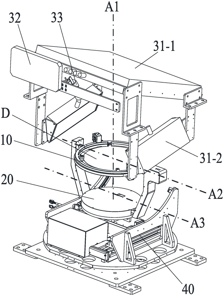
Referring to fig. 1 to 10, an exemplary inspection apparatus for inspecting surface defects of semiconductor devices, including but not limited to wafers, includes a carrier 10, a driving device 20, and an inspection device 30; the following are described separately.
Referring to fig. 1, 2 and 6 to 10, the carrying device 10 is mainly used for carrying and positioning a workpiece D to be inspected, so that the workpiece D to be inspected is fixed on the carrying device 10 in a predetermined posture (or state); in this embodiment, the carrying device 10 mainly includes a receiving member 11, a positioning member 12 and a carrying driving member 13; wherein, regarding the carrying device 10 itself, the receiving part 11 belongs to a static part, and is mainly used for providing structural support for the workpiece D to be detected so as to receive the workpiece D to be detected, and in general, the central line of the receiving part 11 is coincident with the central line of the workpiece D to be detected so that the receiving part 11 can provide a full-area or uniform supporting force for the workpiece D to be detected; at the same time, the power end of the driving device 20 is coupled to the socket 11 to drive the socket 11 to rotate around the first axis a1, so that the whole bearing device 10 with the workpiece D to be inspected carried by the bearing device rotates around the first axis a1 synchronously under the action of the socket 11. The positioning member 12 belongs to a dynamic component or a movable component, and is distributed in parallel with the receiving member 11 along the first axis a1, and is mainly used for abutting against the edge of the workpiece D to be detected, so that the edge of the workpiece D to be detected can be clamped between the receiving member 11 and the positioning member 12, thereby realizing bearing fixation of the workpiece D to be detected, and simultaneously, the surface of the workpiece D to be detected can be exposed out of the bearing device 10, so as to provide conditions for surface defect detection of the workpiece D to be detected. The bearing driving part 13 belongs to a power output part and is mainly used for driving the positioning part 12 to approach or depart from the bearing part 11 along the first axis a1, and if the positioning part 12 is driven to approach the bearing part 11, the workpiece D to be detected can be clamped and fixed between the positioning part 12 and the bearing part 11, so that the bearing fixation of the workpiece D to be detected is realized; if the positioning member 12 is driven to be away from the receiving member 11, the workpiece D to be detected can be conveniently taken out from between the positioning member and the receiving member to realize the blanking operation, or the workpiece D to be detected is placed on the receiving member 11 through a gap between the positioning member and the receiving member to realize the loading operation; the bearing driving member 13 mainly comprises a power driving device such as a motor, a cylinder, etc., and the body thereof is fixedly connected to the receiving member 11, and the power end thereof is coupled to the positioning member 12 (of course, the body of the driving member 13 may also be fixedly connected to the positioning member 12, and the power end thereof is coupled to the receiving member 11). Meanwhile, in some embodiments, to ensure the smoothness of the movement of the positioning member 12, a plurality of positioning members may be provided and distributed around the center of the positioning member 12, such as two positioning members symmetrically distributed with respect to the center of the positioning member 12.
In another embodiment, the carrying device 10 may also be a suction cup type structure, that is, it is mainly composed of a disk body with vacuum holes, and the vacuum holes are communicated with a device such as a vacuum pump through a pipeline, so as to generate a vacuum adsorption effect on the disk body, thereby directly adsorbing and fixing the workpiece D to be inspected on the disk body, and realizing the adsorption type carrying of the workpiece D to be inspected; the power end of the driving device 20 is coupled to the tray to drive the tray to rotate or otherwise move about the first axis a1 to adjust the spatial position, angle, etc. of the workpiece D to be inspected in the inspection environment.
Referring to fig. 1, 2 and 6 to 10, the driving device 20 is mainly used for driving the carrying device 10 to rotate around the first axis a1, so that the designated or inspected portion on the surface of the workpiece D to be inspected carried by the carrying device can reach the position or angle that can be inspected by the inspection device 30. In the embodiment, the driving device 20 is disposed in the lower space of the carrying device 10, and may be composed of power components such as a motor and a cylinder, and other accessories used as needed according to actual situations; if the body of the motor is disposed at a predetermined position in the space below the carrying device 10, the power shaft is coupled to the bottom surface of the receiving member 11, so that the carrying device 10 is driven to rotate around the first axis a1 by the rotational power output from the motor.
Referring to fig. 1, 2, 6 and 7, the detecting device 30 is mainly used for detecting defects on the surface of the workpiece D to be inspected, which is supported and fixed on the supporting device 10, and is disposed in the space above the supporting device 30, and mainly includes a light emitting element 31, an observation window 32 and an image capturing element 33. The light emitting element 31 is mainly used for emitting detection light (such as visible light), and by irradiating the surface of the workpiece D to be inspected, the detection light is reflected and/or scattered by the workpiece D to be inspected to form a detection light signal. The observation window 32 is mainly used for providing a structural channel or a spatial position for an inspector to observe the workpiece D to be inspected, and may be a transparent window arranged at a certain preset position on the inspection device 30, such as a glass window, or a structural position naturally formed at a certain preset position on the inspection device 30 based on the structural characteristics of the inspection device 30, and when the driving device 20 drives the bearing device 10 to drive the workpiece D to be inspected to rotate around the first axis a1 and stay at a certain position, an inspection optical signal formed by reflection and/or scattering of the workpiece D to be inspected may be incident to human eyes, so that the inspector can observe a local position of the workpiece D to be inspected facing the observation window 32 or a whole area of the surface of the workpiece D to be inspected through the observation window 32, and determine whether a defect exists at the position in a manual determination manner. The image acquisition part 33 is mainly used for acquiring a surface image of the workpiece D to be inspected, for example, the image acquisition part 33 may be a camera to acquire a still image of the workpiece D to be inspected by photographing the workpiece D to be inspected; the image acquisition part 33 can also be a camera to acquire a dynamic image of the workpiece D to be detected by shooting an image of the workpiece D to be detected; depending on the structural configuration of the inspection device 30 itself or the existence of the observation window 32, the image capturing member 33 is disposed in the observation window 32 or within the outline of the observation window 32, so that for the workpiece D to be inspected, since the image capturing member 33 and the observation window 32 are located at a substantially same position, when the driving device 20 drives the carrying device 10 to drive the workpiece D to be inspected to move so that a certain region position of the workpiece D to be inspected reaches a position corresponding to the lens portion of the image capturing member 33, the inspection light signal will be incident to the eye of the inspector and the lens portion of the image capturing member 33 at the same time, so that the two members observe the same region position of the workpiece D to be inspected at a substantially same viewing angle or observation path; in specific implementation, when a detector observes that a defect exists at a certain region of the workpiece D to be detected through the observation window 32, the image acquisition element 33 can also photograph or record the defect at the same time or in time, and in the subsequent defect analysis and determination process, the detector can calibrate the observed defect in the image acquired by the image acquisition element 33, so as to use the acquired image to assist the detector in detecting the workpiece D to be detected, or search the source of the defect according to the image analysis of a plurality of calibrated defects.
In one embodiment, a non-transparent closing door capable of being selectively opened or closed may be disposed at the observation window 32, and when the inspection personnel observes the workpiece D to be inspected through the observation window 32, the closing door may be in an opening device, and when the inspection personnel completes the observation and needs to perform image acquisition on the surface of the workpiece to be inspected by using the image acquisition member 33, the closing door may be in a closed state, so as to prevent the ambient light from affecting the quality of the image acquired by the image acquisition member 33.
Firstly, the observation window 32 and the image acquisition part 33 are arranged at the basically same position, so that the manual observation and the equipment visual detection of the same area position on the surface of the workpiece D to be detected can be completed at the basically same visual angle or observation path, the synchronous and same-position manual observation and the equipment visual detection are realized, and the detection efficiency is effectively improved; for example, when the observation window 32 and the image capturing element 33 are disposed at different positions, the driving device 20 is often required to drive the carrying device 10 to drive the workpiece D to be detected to be switched between the position corresponding to the viewing angle of the observation window 32 and the position corresponding to the viewing angle of the image capturing element 33, so that not only is the detection process time-consuming, but also a complicated control scheme needs to be configured for adjusting the movement stroke or posture of the carrying device 10, thereby increasing the detection cost.
Secondly, the surface defects of the workpiece D to be detected are detected in a mode of combining human eye observation and automatic equipment detection, so that the detection quality can be ensured, for example, because the surface defects observed by the human eyes through the observation window 32 and the surface defects on the image acquired by the image acquisition part 30 have the correspondence or consistency of the region positions, the detection personnel can conveniently, quickly and accurately mark the defects in the image, and then the root cause of the defects is searched through the subsequent analysis of the image.
Thirdly, by utilizing the movement form of the positioning piece 12 and the matching relation between the positioning piece and the bearing piece 11, when the bearing device 10 is adjusted to the horizontal position, a gripping device such as a mechanical arm can conveniently take and place the workpiece to be loaded along the horizontal direction, so that the loading or unloading operation of the bearing device 10 is realized; the rapid loading and unloading operation can be used for creating favorable conditions for improving the detection efficiency, and sufficient structural space does not need to be configured between the detection device 30 and the bearing device 10 for the grabbing device and the picking and placing of the workpiece D to be detected, so that conditions are created for enhancing the structural compactness of the whole equipment.
In one embodiment, referring to fig. 3 in combination with fig. 1, 2, 6 and 7, the center of the observation window 32 coincides with or is on the same straight line as the center of the image capturing element 33, for example, the center of the observation window 32 falls on the optical axis of the camera lens, so as to maintain the viewing angle or observation path observed by human eyes to be consistent with the image capturing element 33 to the maximum extent, thereby creating conditions for improving the detection efficiency and the final detection quality; specifically, referring to fig. 3, a connection line between a projection of the first axis a1 on the reference plane B perpendicular to the first axis a1 and a projection of the center of the observation window 32 on the reference plane B is a first connection line L1, a connection line between the projection of the center of the image capturing element 33 on the reference plane B is a second connection line L2, and the second connection line L2 is overlapped with the first connection line L1.
In one embodiment, referring to fig. 8 and 9, the positioning member 12 is mainly composed of a positioning ring 12-1 and a pressing arm 12-2; wherein, the positioning ring 12-1 is mainly a ring structure, the outline shape of which can be the same as the outline shape of the workpiece D to be detected, if the workpiece D to be detected is a wafer, the positioning ring 12-1 can adopt a ring structure body with the size larger than that of the wafer; after the workpiece D to be detected is placed on the bearing part 11, the positioning ring 12-1 is arranged around the edge of the workpiece D to be detected, and the positioning ring 12-1 is connected with a body or a power end bearing the driving part 13; the pressing arms 12-2 are mainly used for pressing the edge of the workpiece D to be detected, so as to finally clamp and fix the edge of the workpiece D to be detected on the receiving member 11, and are arranged on the inner peripheral side of the positioning ring 12-1, the number of the pressing arms 12-2 can be one or more, as shown in the illustrated embodiment, the four pressing arms 12-2 are uniformly distributed around the center line or the first axis a1 of the positioning ring 12-1, so as to ensure that the uniformly distributed pressing arms 12-2 are used for uniformly applying force to the edge of the workpiece D to be detected, so that the problems of warping, sagging, mechanical damage and the like of the workpiece due to nonuniform stress are prevented, and favorable conditions are created for surface detection of the workpiece D to be detected. In another embodiment, the positioning element 12 may also be a structural element similar to the structure and function of the pressing arm 12-2, and the positioning element 12 is arranged uniformly around the first axis a1 and is connected with a carrying driving element 13 in a one-to-one correspondence, so as to clamp the edge of the workpiece D to be inspected between the positioning element and the receiving element 11.
In one embodiment, referring to fig. 8 and 9, the receiving member 11 may adopt a structural form the same as or similar to that of the positioning member 12, for example, the receiving member 11 includes a receiving ring 11-1 and a receiving arm 11-2, the receiving ring 11-1 and the positioning ring 12-1 have the same shape and size, and the receiving arm 11-2 and the pressing arm 12-2 are in one-to-one alignment fit, so that the receiving ring 11-1 and the positioning ring 12-1 may provide a structural basis for assembling the load-bearing driving member 13, and the alignment relationship between the receiving arm 11-2 and the pressing arm 12-2 may clamp the edge of the workpiece D to be detected, thereby effectively simplifying the structure of the entire load-bearing apparatus 10 and reducing the load of itself or the driving apparatus 20. In another embodiment, the receiving member 11 may be a tray structure, the shape of which may be the same as the shape of the workpiece D to be inspected, and the positioning member 12 needs to be located within the contour of the receiving member 11.
In one embodiment, referring to fig. 8 and 9, the bearing driving member 13 uses an air cylinder as a power element, a body of the air cylinder is fixedly connected to the receiving member 11, and a guide rail 13-1 distributed parallel to the first axis a1 is disposed on the body of the air cylinder, a power end of the air cylinder is connected to the sliding block 13-2, one end of the sliding block 13-2 is fixedly connected to the positioning member 12, and the other end of the sliding block 13-2 is slidably connected to the guide rail 13-1, so that the sliding block 13-2 slides on the guide rail 13-1 along a direction parallel to the first axis a1 under the driving of the air cylinder, and the positioning member 12 is driven to approach or depart from the receiving member 11 along the first axis a 1. In another embodiment, the supporting member 13 may also use a motor as a power element, and the power end of the motor is in the form of a lead screw screwed to the sliding block 13-2, so as to drive the positioning member 12 to approach or move away from the bearing member 11.
In one embodiment, referring to fig. 9, a receiving opening 14 is formed between the receiving member 11 and the positioning member 12, the receiving opening 14 is located at an edge of the carrying device 10, and an opening direction of the receiving opening is parallel to the reference plane B, so that the workpiece D to be detected can enter and exit the carrying device 10 in a horizontal direction. In this embodiment, a settling structure may be disposed on a side surface of the receiving member 11 adjacent to the positioning member 12, so as to form a certain structural gap between the receiving member 11 and the positioning member 12, that is: the material receiving opening 14, such as a mechanical arm, can use the structural space provided by the material receiving opening 14 to capture the workpiece D to be inspected so as to pick and place the workpiece D to be inspected.
In one embodiment, referring to fig. 1 to 7, the light emitting element 31 is mainly composed of two light sources, a bright field light source 31-1 and a dark field light source 31-2; the bright field light source 31-1 can be understood as a light source whose position forms a certain angle with the object to be measured, so that most of light can be reflected by the object to be measured and incident on the object to be observed; for the present embodiment, the detection light emitted by the bright field light source 31-1 can illuminate the whole area of the workpiece D to be inspected, and most of the detection light can be reflected by the workpiece D to be inspected to the observation window 32 and the image capturing element 33 to provide bright field illumination for the two, so that the inspector and the image capturing element 33 can observe large-sized contaminants, pits, surface defects such as chip dislocation, and the like; dark field light source 31-2 may be understood to mean a light source positioned such that most of the light is not reflected to the object of observation, and only a specific portion of the light of the object of measurement illuminated is incident to the object of observation; in the present embodiment, the detection light emitted from the dark field light source may be incident on the observation window 32 and the image capturing element 33 after being scattered by the workpiece D to be inspected, so as to provide dark field illumination for both, so that the inspector and the image capturing element 33 can observe small-sized surface defects such as small particle contaminants. In this embodiment, the bright field light source 31-1 may adopt a multispectral surface light source to meet different requirements by emitting detection light of different wavelengths; meanwhile, the light-emitting angle of the bright field light source 31-1 can be adaptively selected according to parameters such as the surface size of the workpiece D to be detected, the distance between the workpiece D to be detected and the like; the dark field light source 31-2 may be a line light source (e.g., LED stripe light source, etc.), and preferably has a length equal to or greater than the maximum length of the surface of the workpiece D to be inspected, such as a diameter equal to or greater than the diameter of the wafer, so that the light reflected or scattered from a specific portion of the surface of the workpiece D to be inspected can be incident on the observation window 32 and the image capturing unit 33. When the bright field light source 31-1 and the dark field light source 31-2 are spatially arranged, based on the structural characteristics of loading and unloading of the bearing device 10 and the alignment relationship between the observation window 32 and the image acquisition part 33, the bright field light source 31-1 can be arranged in the space above the bearing device 10 in a manner of inclining to the horizontal plane, and the bright field light source can irradiate all areas of the workpiece D to be detected by setting the light emitting angle of the bright field light source; dark field light source 31-2 is disposed on the side of bright field light source 31-1 (the side is not the side opposite to observation window 32 or image capturing element 33), and specifically, referring to fig. 3, the projection of first axis a1 on reference plane B perpendicular to first axis a1 is connected to the projection of the center of bright field light 31-1 on reference plane B by third line L3, the projection of the center of dark field light source 31-2 on reference plane B is connected to fourth line L4, and third line L3 is connected to fourth line L4, such as a 90-degree perpendicular intersection or an intersection at another angle. Thus, through the structural layout of the bright field light source 31-1 and the dark field light source 31-2, conditions can be created for adjusting the orientation and the angle of the workpiece D to be detected in the detection environment or space during detection, so as to observe the workpiece D or acquire an image.
In one embodiment, referring to fig. 1, 2, 3, 4, 6 and 7, at least one bright field light source 31-1, at least two dark field light sources 31-2, at least one bright field light source 31-1 is obliquely arranged in the space above the carrier 10, and at least two dark field light sources 31-2 are arranged on both sides of the bright field light source 31-1 with a plane passing through the first axis a1 and the third line L3 as a boundary mirror image; therefore, the dark field illumination effect provided by the dark field light source 31-1 can be ensured, and conditions are created for the bearing device 10 to drive the workpiece D to be detected to rotate around the axis perpendicular to the plane passing through the first axis A1 and the third connecting line L3, so that pitching motion of the workpiece D to be detected is realized, and observation comfort is enhanced.
In an embodiment, referring to fig. 6 in combination with fig. 2, 6, 7 and 10, the driving device 20 is further configured to drive the bearing device 10 to rotate around a second axis a2, so that after the loading operation of the workpiece D to be inspected is completed, the bearing device 10 can drive the workpiece D to be inspected to perform a pitching motion within a certain angle range, so that the surface of the workpiece D to be inspected is finally parallel to the extending direction of the light emitting surface of the dark-field light source 31-2, the illumination effect of the dark-field light source 31-2 on the surface of the workpiece D to be inspected is ensured, and the detection light can be incident to the observation window 32 and the image acquisition element 33 after being scattered by the workpiece D to be inspected; it should be noted that the second axis a2 and the first axis a1 are distributed in a crossing manner, for example, the second axis a2 passes through the center of the workpiece D to be inspected and is in a planar crossing (i.e., intersecting) with the first axis a1, and for example, the second axis a2 and the first axis a1 are also distributed in a spatial crossing manner, and the main point is that the carrying device 10 can drive the workpiece D to be inspected to perform a pitching motion at a certain angle. In a specific embodiment, based on the requirement of comfort and convenience of observation of the inspector, the observation window 32 and the image capturing member 33 may be disposed in the upper space of the carrier 10 at an angle to the first axis a1 (or vertical axis), while the dark field light source 31-2 is disposed in the upper space of the carrier 10 at an angle of 10 to 20 degrees to the horizontal plane; firstly, the driving device 20 is used for driving the bearing device 10 to rotate around a second axis A2, so that the extending direction of the light-emitting surface of the dark field light source 31-2 is parallel to the surface of the workpiece D to be detected, and at this time, the extending direction is equivalent to the optimal angle for the inspector or the image acquisition piece 33 to observe the surface of the workpiece to be detected, which is convenient for the inspector and the image acquisition piece 33 to obtain the detection optical signal and observe the defects on the surface of the workpiece to be detected; then, the bearing device 10 is driven to drive the workpiece D to be detected to rotate around the first axis a1, so that the area of the surface of the workpiece D to be detected is gradually converted into the visual angle range of the detector and the image acquisition part 33, and the surface defects are synchronously acquired in a manner of combining manual observation and equipment visual detection. In another embodiment, the driving device 20 can be used only to drive the carrying device 10 to rotate the workpiece D to be inspected about the first axis a1 in the horizontal plane, and the detecting device is configured with a corresponding driving mechanism to move up and down along the first axis a1 and/or tilt around an axis, so as to adjust the position or angle of the observation window 32 and the image capturing element 33 in the whole apparatus.
In one embodiment, referring to fig. 8, 9 and 10, the driving device 20 mainly includes a supporting member 21, a first driving member 22 and a second driving member 23; the support 21 is mainly used for providing structural support for the carrying device 10 disposed in the space below the detection device 30, and may include a chassis portion 21-1 and two support arms 21-2 formed at the edge of the chassis portion 21-1, where the support arms 21-2 are symmetrically distributed at the edge of the chassis portion 21-1. The first driving member 22 is mainly used for driving the carrying device 10 to rotate around the second axis a2 relative to the supporting member 21, the first driving member 22 may be constructed by combining a motor, an encoder, a limit switch, and other devices, a body of the first driving member 22 is installed at one end of the supporting arm 21-2 away from the chassis part 21-1, a power end of the first driving member 22 is coupled to the carrying device 10 (such as the aforementioned receiving member 11), and a central line of the first driving member 22 is distributed along the second axis a2, so that the power output by the first driving member 22 can drive the carrying device 10 to rotate around the second axis a2, so as to realize a certain angle of pitching motion of the workpiece D to be detected driven by the carrying device 10 in the detection environment or relative to the detection device 30. The second driving member 23 is mainly used for driving the carrying device 10 (together with the supporting member 21 and the workpiece D to be inspected) to rotate around the first axis a1 so as to adjust the position relationship between the specific portion of the surface of the workpiece D to be inspected and the observation window 32 and the image capturing member 33, the second driving member 23 can also be formed by combining a motor, an encoder and the like, the body of the second driving member 23 can be fixedly arranged at a preset position in the space below the chassis part 21-1, and the power end of the second driving member is coupled to the chassis part 21-1.
Referring to fig. 1, 2, 6, 7 and 10 to 12, an embodiment provides a detection apparatus, further including a rotation device 40, which is mainly used for adjusting a pitch angle of a main body portion of the detection apparatus, such as a structure portion combined by the driving device 20, the carrying device 10 and the workpiece D to be detected, or a structure portion combined by the driving device 20, the carrying device 10, the detection device 30 and the workpiece D to be detected, so as to create conditions for installation, debugging and use of the detection apparatus in a specific environment, for example, by adjusting the main body portion, the entire apparatus, especially the observation window 32 and the like can be adapted to physical conditions of a detection person, so as to observe the workpiece D to be detected at a more comfortable angle. In particular, the swivelling means 40 are intended to enable at least the driving means 20 and the carrying means 10 to oscillate synchronously about a third axis A3 parallel to the second axis a 2; it comprises a supporting seat 41, a guide slide block 42, an arc guide rail 43 and a third driving piece 44; wherein, the supporting seat 41 can be installed on the body of the second driving member 22 to fix the whole driving device on the revolving device 40; the guide sliders 42 can be installed at two symmetrical ends of the support base 41, the arc-shaped guide rails 43 correspond to the guide sliders 42 one by one, and are located at two symmetrical sides of the space below the supporting seat 41, the third axis a3 passes through the center of the arc-shaped guide rail 43, so that the radian of the arc-shaped guide rail 43 can be adapted to the included angle between the dark field light source 31-2 and the horizontal plane, the guide slider 42 is slidably connected to the corresponding arc-shaped guide rail 43, the third driving member 44 can be assembled and constructed by power devices such as an air cylinder or a motor and mechanism components such as a screw rod transmission mechanism, a link mechanism and the like which need to be used in cooperation, the body of the third driving member 44 is fixed at a preset position in the space below the supporting seat 41, the power end of the power end is coupled on the guide slide block 42, so as to drive the guide slide block 42 to slide on the arc-shaped guide rail 43, and the driving device 20, the carrying device 10 and/or the detecting device 30 are driven by the supporting seat 41 to adjust and change the pitch angle.
In one embodiment, referring to fig. 11 and 12, the swiveling device 40 further includes a base plate 45 and a fourth driving member 46; the arc-shaped guide rail 43 and the body of the third driving member 44 are both fixedly mounted on the chassis 45, so that the main body of the revolving device 40 and the driving device 20 are arranged on the chassis 45 together, the fourth driving member 46 can adopt power components such as a motor, the body of the fourth driving member is fixed at a certain preset position in the space below the chassis 45, and the power end of the fourth driving member 46 is coupled to the chassis 45 to drive the chassis 45 to perform rotary motion around the center of the chassis 45, so as to drive the whole detection equipment to rotate; the direction of the equipment main body is adjusted; during specific implementation, the directions of the observation window 32, the loading and unloading of the workpiece D to be detected and the like can be adjusted according to actual conditions in an environment space, and conditions are created for enhancing the adaptability of the whole equipment to the environment.
It is right to have used specific individual example above the utility model discloses expound, only be used for helping to understand the utility model discloses, not be used for the restriction the utility model discloses. To the technical field of the utility model technical personnel, the foundation the utility model discloses an idea can also be made a plurality of simple deductions, warp or replacement.