CN215203153U - Movable discharging mechanism of injection molding machine - Google Patents
Movable discharging mechanism of injection molding machine Download PDFInfo
- Publication number
- CN215203153U CN215203153U CN202121794132.8U CN202121794132U CN215203153U CN 215203153 U CN215203153 U CN 215203153U CN 202121794132 U CN202121794132 U CN 202121794132U CN 215203153 U CN215203153 U CN 215203153U
- Authority
- CN
- China
- Prior art keywords
- injection molding
- molding machine
- feeding bin
- stirring
- bin
- Prior art date
- Legal status (The legal status is an assumption and is not a legal conclusion. Google has not performed a legal analysis and makes no representation as to the accuracy of the status listed.)
- Active
Links
Images


Landscapes
- Injection Moulding Of Plastics Or The Like (AREA)
Abstract
The utility model provides an injection molding machine activity unloading mechanism, which belongs to the technical field of injection molding machines, and comprises an injection molding machine, wherein the top end of the injection molding machine is provided with a second feeding bin, the injection molding machine is communicated with the second feeding bin, the top end of the second feeding bin is provided with a first feeding bin, the first feeding bin is communicated with the second feeding bin, a first stirring blade is arranged in the first feeding bin and is used for stirring raw materials entering the injection molding machine, a second stirring blade is arranged in the second feeding bin and is used for further enhancing the stirring effect of the first stirring blade; the second stirring leaf drives through the pivot, and the first top of going into the feed bin is equipped with gear drive assembly, and gear drive assembly is used for driving the second stirring leaf and carries out and the stirring of first stirring leaf opposite direction, need not artifical on duty, greatly increased the stability of production efficiency and unloading.
Description
Technical Field
The utility model belongs to the technical field of the injection molding machine, concretely relates to injection molding machine activity unloading mechanism.
Background
An injection molding machine is also known as an injection molding machine or an injection machine. It is a main forming equipment for making various shaped plastic products from thermoplastic plastics or thermosetting plastics by using plastic forming mould. The device is divided into a vertical type, a horizontal type and a full-electric type. The injection molding machine can heat the plastic, apply high pressure to the molten plastic, make it inject out and fill the die cavity;
the existing blanking mechanism cannot guarantee quick, efficient and automatic material pushing and cannot block a blanking port of an injection molding machine, manual guard is needed, production efficiency and blanking stability are greatly reduced, different types of plastic particles are mixed together for use, the existing blanking device is simple in structure, materials cannot be uniformly stirred during blanking, and the feeding port is easily blocked.
SUMMERY OF THE UTILITY MODEL
An object of the utility model is to provide an injection molding machine activity unloading mechanism, current unloading mechanism that aims at solving among the prior art can't guarantee to push away material fast, high-efficient, automatically and can not block up injection molding machine feed opening, need artifical on duty, greatly reduced the stability of production efficiency and unloading, because plastic granules has different kinds to mix and use in one, and current unloader simple structure, can't evenly stir the material when the unloading, and the feed inlet is blockked up the problem easily.
In order to achieve the above object, the utility model provides a following technical scheme:
the movable blanking mechanism of the injection molding machine comprises the injection molding machine, wherein a second feeding bin is arranged at the top end of the injection molding machine, the injection molding machine is communicated with the second feeding bin, a first feeding bin is arranged at the top end of the second feeding bin, the first feeding bin is communicated with the second feeding bin, a first stirring blade is arranged in the first feeding bin and used for stirring raw materials entering the injection molding machine, a second stirring blade is arranged in the second feeding bin and used for further enhancing the stirring effect of the first stirring blade;
the second stirring blade is driven through the rotating shaft, the top end of the first feeding bin is provided with a gear transmission assembly, and the gear transmission assembly is used for driving the second stirring blade to stir in the direction opposite to that of the first stirring blade.
As an optimal scheme, the side of installation shell is equipped with the pivot, the pivot activity runs through to first income feed bin in, the top of installation shell is equipped with driving motor, driving motor is connected with the pivot through the shaft coupling, the circumferential surface of pivot is located to second stirring leaf.
As an optimal scheme, the gear drive subassembly is including rotating the drum of connecting in first pan feeding storehouse side, the drum activity runs through to first income feed bin in, the top of drum is equipped with second drive gear, the pivot is rotated and is connected in second drive gear and drum, the circumferential surface of pivot is equipped with first drive gear, the circumferential surface of drum is located to first stirring leaf.
As an optimal scheme, the first top of going into the feed bin is rotated and is connected with the driven shaft, the circumferential surface of driven shaft is equipped with first drive gear and second drive gear, first drive gear and first drive gear mesh mutually, the first top of going into the feed bin is equipped with driven gear, driven gear and second drive gear mesh mutually, second drive gear and driven gear mesh mutually.
As an optimized scheme, the pan feeding mouth has been seted up on the first top of going into the feed bin, the pan feeding mouth department on first income feed bin top is equipped with the feeding spare, be equipped with the anti-overflow board in the feeding spare.
As an optimal scheme, the first bottom of going into the feed bin is equipped with a plurality of support frames, and the top of injection molding machine is all located to the bottom of a plurality of support frames.
As an optimal scheme, the circumferential surface of pivot is equipped with carries the auger, carry the auger and locate in the second goes into the feed bin, the discharge gate has been seted up to the side that the feed bin was gone into to the second, the discharge gate goes out to be equipped with the closing plate, the side of closing plate is equipped with the handle.
Compared with the prior art, the beneficial effects of the utility model are that:
1. in this device, make two sets of stirring leaves carry out opposite direction's motion through utilizing the gear drive subassembly, when can guaranteeing the feeding, the pan feeding mouth can not be plugged up to the raw materials, need not artifical on duty, greatly increased production efficiency and the stability of unloading.
2. In the device, the discharge port is arranged in the second feeding bin, so that the raw materials at the discharging position can be removed when the injection molding machine stops working through the discharge port, the waste of resources is avoided, and the next use cannot be influenced.
Drawings
The accompanying drawings are included to provide a further understanding of the invention, and are incorporated in and constitute a part of this specification, illustrate embodiments of the invention, and together with the description serve to explain the invention and not to limit the invention. In the drawings:
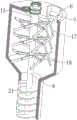
fig. 1 is a front view of the present invention;
fig. 2 is a first partial perspective view of the present invention;
fig. 3 is a second partial perspective view of the present invention;
fig. 4 is a partial sectional view of the present invention.
In the figure: 1. an injection molding machine; 2. a first feeding bin; 3. a second feeding bin; 4. a support frame; 5. mounting a shell; 6. feeding a material part; 7. an anti-overflow plate; 8. a rotating shaft; 9. a first drive gear; 10. a second drive gear; 11. a driven gear; 12. a driven shaft; 13. a first drive gear; 14. a second transmission gear; 15. a cylinder; 16. a drive motor; 17. a first stirring blade; 18. a second stirring blade; 19. a sealing plate; 20. a handle; 21. and (5) conveying the packing auger.
Detailed Description
The technical solutions in the embodiments of the present invention will be described clearly and completely with reference to the accompanying drawings in the embodiments of the present invention, and it is obvious that the described embodiments are only some embodiments of the present invention, not all embodiments. Based on the embodiments in the present invention, all other embodiments obtained by a person skilled in the art without creative work belong to the protection scope of the present invention.
Examples
Referring to fig. 1-4, the present invention provides the following technical solutions:
the movable blanking mechanism of the injection molding machine comprises an injection molding machine 1 and is characterized in that a second feeding bin 3 is arranged at the top end of the injection molding machine 1, the injection molding machine 1 is communicated with the second feeding bin 3, a first feeding bin 2 is arranged at the top end of the second feeding bin 3, the first feeding bin 2 is communicated with the second feeding bin 3, a first stirring blade 17 is arranged in the first feeding bin 2, the first stirring blade 17 is used for stirring raw materials entering the injection molding machine, a second stirring blade 18 is arranged in the second feeding bin 3, and the second stirring blade 18 is used for further enhancing the stirring effect of the first stirring blade 17;
the second stirring blade 18 is driven by the rotating shaft 8, and the top end of the first feeding bin 2 is provided with a gear transmission component which is used for driving the second stirring blade 18 to stir in the direction opposite to that of the first stirring blade 17.
The utility model discloses an in the embodiment, in order to make the raw materials get into the injection molding machine from the pan feeding mouth, can not take place to block up, and need not the people and watch on, set up a set of rabbling mechanism in feed mechanism, it is broken to stirring raw and other materials through second stirring leaf 18, make it refine and become the subtotal, can not block up the pan feeding mouth, and need not artifical watch on, in order to avoid having the raw and other materials of great piece, once stir and be difficult to refine completely, secondary rabbling mechanism has been set up, and drive secondary rabbling mechanism through the gear drive subassembly and go on and the rotation that an rabbling mechanism motion opposite direction, stirring efficiency has further been increased.
Specifically referring to fig. 1 and 2, 5 is arranged at the top end of the mounting shell 5, a rotating shaft 8 is arranged at the side end of the mounting shell 5, the rotating shaft 8 movably penetrates into the first feeding bin 2, a driving motor 16 is arranged at the top end of the mounting shell 5, the driving motor 16 is connected with the rotating shaft 8 through a coupler, and a second stirring blade 18 is arranged on the circumferential surface of the rotating shaft 8.
In this embodiment: the rotation shaft 8 is driven to rotate by the driving motor 16, and the second stirring blade 18 is driven to perform primary stirring by the rotation of the rotation shaft 8.
Specifically referring to fig. 2 and 3, the gear transmission assembly includes a cylinder 15 rotatably connected to a side end of the first material inlet bin 2, the cylinder 15 movably penetrates into the first material inlet bin 2, a second driving gear 10 is disposed at a top end of the cylinder 15, a rotating shaft 8 is rotatably connected to the second driving gear 10 and the cylinder 15, a first driving gear 9 is disposed on a circumferential surface of the rotating shaft 8, and a first stirring blade 17 is disposed on a circumferential surface of the cylinder 15.
In this embodiment: the cylinder 15 is used for driving the first stirring plate blade 17 to stir the plate for the second time, so that the stirring effect of the feeding port is further enhanced.
Specifically referring to fig. 2 and 3, a driven shaft 12 is rotatably connected to the top end of the first material inlet bin 2, a first transmission gear 13 and a second transmission gear 14 are arranged on the circumferential surface of the driven shaft 12, the first transmission gear 13 is meshed with the first driving gear 9, a driven gear 11 is arranged at the top end of the first material inlet bin 2, the driven gear 11 is meshed with the second driving gear 10, and the second transmission gear 14 is meshed with the driven gear 11.
In this embodiment: in order to allow movement of cylinder 15 in the opposite direction to shaft 8, an intermediate drive gear set is provided to allow movement of cylinder 15 in the opposite direction to shaft 8, using the principle that meshing gears will drive the other gear in the opposite direction.
Referring to fig. 2 specifically, a feeding port is formed at the top end of the first feeding bin 2, a feeding member 6 is arranged at the feeding port at the top end of the first feeding bin 2, and an anti-overflow plate 7 is arranged in the feeding member 6.
In this embodiment: the raw materials can be sent into the blanking mechanism through the feeding part 6, and the raw materials cannot overflow when being stirred in the bin through the anti-overflow plate 7.
Referring to fig. 1 specifically, a plurality of support frames 4 are arranged at the bottom end of the first feeding bin 2, and the bottom ends of the support frames 4 are all arranged at the top end of the injection molding machine 1.
In this embodiment: in order to prevent that first income feed bin 2 can be when stirring work goes on remain stable, be equipped with a plurality of support frames 4 in first income feed bin 2's bottom, be fixed in injection molding machine 1's top with first income feed bin 2 through a plurality of support frames 4, guaranteed the stability when the device moves.
Referring to fig. 1 specifically, a conveying auger 21 is arranged on the circumferential surface of the rotating shaft 8, the conveying auger 21 is arranged in the second feeding bin 3, a discharge port is formed in the side end of the second feeding bin 3, a sealing plate 19 is arranged at the discharge port, and a handle 20 is arranged at the side end of the sealing plate 19.
In this embodiment: rotate through pivot 8 and drive and carry auger 21 to rotate, carry auger 21 pivoted in-process, will stir in the orderly injection molding machine that sends into of complete raw materials, guarantee can not take place to block up, through being equipped with the discharge gate in second income feed bin 3, can be at the injection molding machine during stop work through the discharge gate, get rid of the raw materials of unloading department, avoided the waste of resource, can not influence next use simultaneously yet.
The utility model discloses a theory of operation and use flow: when the device is used, the driving motor 16 is started, the driving motor 16 drives the rotating shaft 8 to rotate, the rotating shaft 8 rotates to drive the second stirring blade 18 arranged on the circumferential surface of the rotating shaft 8 to rotate and stir, the rotating shaft 8 rotates to drive the first driving gear 9 arranged on the circumferential surface of the rotating shaft 8 to rotate, the first driving gear 9 rotates to drive the first driving gear 13 to rotate, the first driving gear 13 rotates to drive the driven shaft 12 to rotate, the driven shaft 12 rotates to drive the second driving gear 14 to rotate, the second driving gear 14 rotates to drive the driven gear 11 meshed with the second driving gear 14 to rotate, the driven gear 11 rotates to drive the second driving gear 10 to rotate, the second driving gear 10 drives the cylinder 15 to rotate, the cylinder 15 rotates to drive the first stirring blade 17 arranged on the circumferential surface of the cylinder 15 to stir, the stirring direction of the first stirring blade 17 is opposite to that of the second stirring blade 18, further enhancing the stirring efficiency and ensuring that the raw materials can not block the feeding port.
It is noted that, herein, relational terms such as first and second, and the like may be used solely to distinguish one entity or action from another entity or action without necessarily requiring or implying any actual such relationship or order between such entities or actions. Also, the terms "comprises," "comprising," or any other variation thereof, are intended to cover a non-exclusive inclusion, such that a process, method, article, or apparatus that comprises a list of elements does not include only those elements but may include other elements not expressly listed or inherent to such process, method, article, or apparatus.
The foregoing is only a preferred embodiment of the present invention, and it should be noted that, for those skilled in the art, various modifications and decorations can be made without departing from the technical principle of the present invention, and these modifications and decorations should also be regarded as the protection scope of the present invention.
Claims (7)
1. The movable blanking mechanism of the injection molding machine comprises the injection molding machine (1) and is characterized in that a second feeding bin (3) is arranged at the top end of the injection molding machine (1), the injection molding machine (1) is communicated with the second feeding bin (3), a first feeding bin (2) is arranged at the top end of the second feeding bin (3), the first feeding bin (2) is communicated with the second feeding bin (3), a first stirring blade (17) is arranged in the first feeding bin (2), the first stirring blade (17) is used for stirring raw materials entering the injection molding machine, a second stirring blade (18) is arranged in the second feeding bin (3), and the second stirring blade (18) is used for further enhancing the stirring effect of the first stirring blade (17);
the second stirring blade (18) is driven through a rotating shaft (8), a gear transmission assembly is arranged at the top end of the first feeding bin (2), and the gear transmission assembly is used for driving the second stirring blade (18) to stir in the direction opposite to that of the first stirring blade (17).
2. The movable blanking mechanism of an injection molding machine according to claim 1, characterized in that: the top of first income feed bin (2) is equipped with installation shell (5), the side of installation shell (5) is equipped with pivot (8), pivot (8) activity runs through to first income feed bin (2) in, the top of installation shell (5) is equipped with driving motor (16), driving motor (16) are connected through shaft coupling and pivot (8), the circumference surface of pivot (8) is located in second stirring leaf (18).
3. The movable blanking mechanism of an injection molding machine according to claim 2, characterized in that: the gear transmission assembly is connected in the first drum (15) of entering feed bin (2) side including rotating, drum (15) activity runs through to first entering feed bin (2) in, the top of drum (15) is equipped with second drive gear (10), pivot (8) rotate to be connected in second drive gear (10) and drum (15), the circumferential surface of pivot (8) is equipped with first drive gear (9), the circumferential surface of drum (15) is located in first stirring leaf (17).
4. The movable blanking mechanism of an injection molding machine according to claim 3, characterized in that: the top of first income feed bin (2) is rotated and is connected with driven shaft (12), the circumferential surface of driven shaft (12) is equipped with first drive gear (13) and second drive gear (14), first drive gear (13) and first drive gear (9) mesh mutually, the first top of entering feed bin (2) is equipped with driven gear (11), driven gear (11) and second drive gear (10) mesh mutually, second drive gear (14) and driven gear (11) mesh mutually.
5. The movable blanking mechanism of an injection molding machine according to claim 4, characterized in that: the material inlet has been seted up on the top of first income feed bin (2), the material inlet department on first income feed bin (2) top is equipped with into material spare (6), be equipped with anti-overflow board (7) in material spare (6).
6. The movable blanking mechanism of an injection molding machine according to claim 5, characterized in that: the bottom of first income feed bin (2) is equipped with a plurality of support frames (4), and the top of injection molding machine (1) is all located to the bottom of a plurality of support frames (4).
7. The movable blanking mechanism of an injection molding machine according to claim 6, characterized in that: the circumference surface of pivot (8) is equipped with carries auger (21), carry auger (21) to locate in the second goes into feed bin (3), the discharge gate has been seted up to the side that feed bin (3) was gone into to the second, the discharge gate goes out to be equipped with closing plate (19), the side of closing plate (19) is equipped with handle (20).
Priority Applications (1)
| Application Number | Priority Date | Filing Date | Title |
|---|---|---|---|
| CN202121794132.8U CN215203153U (en) | 2021-08-03 | 2021-08-03 | Movable discharging mechanism of injection molding machine |
Applications Claiming Priority (1)
| Application Number | Priority Date | Filing Date | Title |
|---|---|---|---|
| CN202121794132.8U CN215203153U (en) | 2021-08-03 | 2021-08-03 | Movable discharging mechanism of injection molding machine |
Publications (1)
| Publication Number | Publication Date |
|---|---|
| CN215203153U true CN215203153U (en) | 2021-12-17 |
Family
ID=79426737
Family Applications (1)
| Application Number | Title | Priority Date | Filing Date |
|---|---|---|---|
| CN202121794132.8U Active CN215203153U (en) | 2021-08-03 | 2021-08-03 | Movable discharging mechanism of injection molding machine |
Country Status (1)
| Country | Link |
|---|---|
| CN (1) | CN215203153U (en) |
-
2021
- 2021-08-03 CN CN202121794132.8U patent/CN215203153U/en active Active
Similar Documents
| Publication | Publication Date | Title |
|---|---|---|
| CN111016073A (en) | Discharging device of plastic injection molding machine | |
| CN210705724U (en) | Washing machine closing cap processing injection molding machine | |
| CN215203153U (en) | Movable discharging mechanism of injection molding machine | |
| CN208714352U (en) | A kind of injection molding auxiliary feeding device | |
| CN212312466U (en) | Feeding device for plastic mold | |
| CN215095211U (en) | Injection molding device is used in production of plastics clothes hanger | |
| CN209903775U (en) | Injection molding mechanism of injection molding machine | |
| CN212312579U (en) | Injection molding device capable of preventing feeding blockage | |
| CN207724731U (en) | A kind of injection molding machine hopper filter device of Automobile Plastic Parts production and processing | |
| CN219095734U (en) | Hopper structure for plastic injection molding | |
| CN214266436U (en) | Feeding device convenient to clear away sweeps for injection production usefulness | |
| CN217318994U (en) | Waterproof sign indicating number is with injection molding machine with material loading function | |
| CN211763245U (en) | Feeding mechanism for injection molding machine | |
| CN211917525U (en) | Injection molding is moulded plastics with improved generation automatic feeding mechanism | |
| CN219276479U (en) | Blanking structure for injection molding machine | |
| CN212288456U (en) | Novel pressure boost mechanism of moulding plastics | |
| CN210940209U (en) | Injection molding device for rubber seal ring production | |
| CN215550450U (en) | High-pressure gas auxiliary forming injection molding device for plastic parts | |
| CN214773810U (en) | Injection molding machine hot melting mechanism for plastic mold processing | |
| CN220700106U (en) | Plastic stirring device for flange barrel production | |
| CN219294679U (en) | Masterbatch semi-manufactured goods hopper down | |
| CN213618002U (en) | Feeding device for injection molding machine | |
| CN216544179U (en) | Feeder of plastic products production usefulness of anti-spillage | |
| CN217346418U (en) | Prevent blockking up type plastics injection molding machine | |
| CN216501117U (en) | Rim charge recovery unit for rubber and plastic sealing member |
Legal Events
| Date | Code | Title | Description |
|---|---|---|---|
| GR01 | Patent grant | ||
| GR01 | Patent grant |