CN215201848U - An interchangeable head telescopic tool set - Google Patents
An interchangeable head telescopic tool set Download PDFInfo
- Publication number
- CN215201848U CN215201848U CN202120272728.5U CN202120272728U CN215201848U CN 215201848 U CN215201848 U CN 215201848U CN 202120272728 U CN202120272728 U CN 202120272728U CN 215201848 U CN215201848 U CN 215201848U
- Authority
- CN
- China
- Prior art keywords
- handle
- head
- unlocking sleeve
- tool set
- unlocking
- Prior art date
- Legal status (The legal status is an assumption and is not a legal conclusion. Google has not performed a legal analysis and makes no representation as to the accuracy of the status listed.)
- Active
Links
Images


Landscapes
- Details Of Spanners, Wrenches, And Screw Drivers And Accessories (AREA)
Abstract
The utility model provides a flexible instrument stack of interchangeable head, including removable instrument head and handle, handle one end is equipped with the holding hole that can hold removable instrument head, and removable instrument head pegs graft downtheholely at the holding, and joint between removable instrument head and handle is equipped with the unlocking sleeve on the handle, and the unlocking sleeve cup joints the holding hole place end and the accessible of handle and slides and removes the joint cooperation between removable instrument head and handle. The utility model discloses well removable instrument head realizes the locking through joint mode rather than friction mode, is difficult for influencing fixed effect because of wearing and tearing, and is fixed more reliable. And the detachable tool head can be detached and replaced only by sliding the unlocking sleeve, and the operation is simple and convenient.
Description
Technical Field
The utility model relates to a hand tool, more specifically say, it relates to a flexible instrument stack of interchangeable head.
Background
The working part and the handle on the existing tool with the handle are usually fixedly connected, and different tools need to be replaced according to different purposes in the operation process, so that tools with different specifications need to be carried, the burden is heavier, and the carrying and the use are inconvenient. In order to solve the problem of inconvenient carrying and use, people make a lot of improvements, one of the methods is to design the tool head and the handle of the tool into a detachable structure, and meet the requirements of people on different operation environments by replacing different tool heads, thereby greatly reducing the trouble caused by carrying a large number of different tools during operation. However, the existing tool with the detachable tool head is usually fixed through the tight-fit friction force between the tool head and the accommodating hole in the handle, and after the tool head is worn after long-term use, the tool head and the accommodating hole are loosely matched. Therefore, a new design is provided on the market, and a screwdriver handle capable of quickly changing the rod is disclosed in 7.4.2001 as a utility model with the publication number of CN2437458Y, and comprises a handle, a lock nozzle main body and an outer sleeve, and is characterized in that a through cylindrical hole is arranged between the inner wall and the outer wall of a screwdriver rod jack of the lock nozzle main body, a limit top bead is arranged in the through cylindrical hole, a spring is arranged at the rear part of the top bead, and a circle of convex edges are arranged at the rear part of the spring; the outer sleeve is sleeved on the outer wall of the lock nozzle main body in a matching mode, the inner wall of the outer sleeve is provided with a circle of convex edge, the convex edge is in contact with the limiting top bead, and the rear portion of the convex edge is provided with a limiting connecting piece sleeved on the lock nozzle main body and is connected with the rear portion of the outer sleeve in a tight fit mode. However, the utility model discloses a structure is comparatively complicated, and it is more to relate to spare part, and the equipment is troublesome, has not only increased screwdriver production and processing cost, and the consumer is changing screwdriver pole process operation comparatively troublesome simultaneously.
SUMMERY OF THE UTILITY MODEL
In the existing tool with a replaceable tool head, the fixing effect of the tool head is unreliable due to the simple structure; some then fix effectual but the structure is comparatively complicated, in order to overcome these defects, the utility model provides a can obtain reliable fixed flexible instrument stack of interchangeable head of effect by simple structure.
The technical scheme of the utility model is that: the utility model provides a flexible instrument stack of interchangeable head, includes removable instrument head and handle, and handle one end is equipped with the holding hole that can hold removable instrument head, and removable instrument head pegs graft in the holding hole, and joint between removable instrument head and handle is equipped with the unlocking sleeve on the handle, and the unlocking sleeve cup joints the holding hole place end and the accessible of handle and slides and removes the joint cooperation between removable instrument head and handle. The detachable tool head can be locked and unlocked on the handle, and the switching between the locking state and the unlocking state of the detachable tool head is completed through the sliding unlocking sleeve. In the locking state, the detachable tool head and the handle are kept in a clamping state; in the unlocked state, the clamping fit between the removable tool head and the handle is released, and the removable tool head can be drawn out of the accommodating hole. The utility model discloses well removable instrument head realizes the locking through joint mode rather than friction mode, is difficult for influencing fixed effect because of wearing and tearing, and is fixed more reliable. And the detachable tool head can be detached and replaced only by sliding the unlocking sleeve, and the operation is simple and convenient.
Preferably, the handle comprises an inner handle and an outer handle, the inner handle and the outer handle are coaxially nested, one end of the inner handle is exposed, the accommodating hole is positioned in the center of the inner handle, the exposed end of the inner handle is provided with a clamping bead which can move between the inner wall and the outer wall of the inner handle, the unlocking sleeve is sleeved at the exposed end of the inner handle, and the detachable tool head is provided with a clamping bead groove which can be embedded with the clamping bead. When the clamping bead is embedded with the clamping bead groove, the unlocking sleeve seals the retreating space of the clamping bead at the exposed end of the inner handle at the same time, the clamping bead is prevented from retreating from the clamping bead groove, and the removable tool head is blocked in the accommodating hole in a pulling and inserting mode, so that the clamping locking of the removable tool head on the handle is realized. Promote the unlocking sleeve and slide, make the shutoff position of unlocking sleeve move outside the card pearl position, get into the unblock state this moment promptly, when pulling out and inserting the removable instrument head of trading, the extrusion force between card pearl and the card pearl groove can promote the card pearl to shift and retreat and not blockked by the unlocking sleeve, card pearl just so no longer with card pearl groove meshing form the locking, freely pull out and insert the removable instrument head of trading this moment, change other instrument heads or adjust the depth of insertion of removable instrument head on the handle.
Preferably, the detachable tool head comprises a working part and an insertion rod, the working part is fixed at one end of the insertion rod, the insertion rod is inserted in the accommodating hole in a matched mode, and the bead clamping groove is formed in the insertion rod. The detachable tool head implements tool operation through the working part and completes matched installation through the inserted link and the handle.
Preferably, an unlocking cavity and a locking cavity are arranged in the unlocking sleeve, the inner wall of the locking cavity is attached to the outer peripheral surface of the inserted rod in a matched mode, and the inner diameter of the unlocking cavity is larger than that of the locking cavity. The unlocking cavity and the locking cavity ensure that the unlocking sleeve has locking and unlocking functions, when the locking cavity moves to the position of the clamping bead, the inner wall of the locking cavity is attached to the outer peripheral surface of the insertion rod, so that the clamping bead can be prevented from retreating and only can stay in the clamping bead groove, and the locking function is realized; when the unlocking cavity moves to the position of the clamping bead, because the inner diameter of the unlocking cavity is larger than that of the locking cavity, a gap exists between the unlocking cavity wall and the outer peripheral surface of the insertion rod, the clamping bead can be held to retreat and is separated from the clamping bead groove, and the unlocking function is realized.
Preferably, at least one axial convex rib is arranged on the inner wall of the accommodating hole, an axial groove corresponding to the axial convex rib is arranged on the inserted link, and the axial convex rib and the axial groove are in fit embedding. After the axial convex rib and the axial groove are embedded, a key connection structure is formed, so that torque transmission is realized between the handle and the detachable tool head.
Preferably, the clamping bead grooves are positioned in the axial grooves, and at least two clamping bead grooves are positioned in the same axial groove. The clamping bead groove is positioned in the axial groove, correspondingly, the clamping bead is also embedded in the axial convex rib, and the axial convex rib is relatively larger in radial size, so that a space for accommodating the clamping bead is formed, and the clamping bead is reliably arranged on the inner handle. The clamping bead grooves in the same axial groove are multiple, so that the replaceable tool head can be inserted into the handle at different depths and locked, and can be better adapted to different working spaces or obtain required tool working distances.
Preferably, a locking spring for axially pushing the unlocking sleeve is arranged between the unlocking sleeve and the inner handle. The elasticity that the locking spring provided makes the unlocking sleeve stop on the position that corresponds with the card pearl when not receiving external force, prevents to block the pearl and moves out card pearl groove, ensures that removable tool bit locking of trading under the normality is on the handle.
Preferably, the inner handle is connected with the outer handle through an over-molded structure. The tool generally has an insulating requirement, and therefore the handle is generally required to be covered with an insulating material. The outer handle can be made of plastics and is combined with the inner handle through an encapsulation injection molding process, so that the combination strength can be ensured, and an insulation function is generated.
Preferably, the inner handle is provided with a roughened portion. The coarsening part enables the surface roughness of the inner handle to be more occlusal surfaces between the inner handle and the outer handle when the inner handle and the outer handle are subjected to encapsulation injection molding processing, so that the inner handle is firmly combined with the outer handle.
The utility model has the advantages that:
the fixing effect is good. The utility model discloses the mode through card pearl joint is realized removable tool bit locking through the mode of card pearl joint rather than close-fitting frictional force, and friction dynamics and frequency are lower, and wear is littleer, and life is longer, and is fixed more reliable.
The operation is convenient. The utility model discloses switching between locking state, unblock state can be accomplished convenient operation through the simple operation of slip unlocking sleeve.
The structure is simple. The utility model discloses spare part is less, and it is simple to connect the cooperation relation, and the processing equipment of being convenient for can reduce the production and processing cost.
Drawings
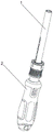
Fig. 1 is a schematic structural view of the present invention;
fig. 2 is a schematic view of a disassembled structure of the present invention;
FIG. 3 is a schematic longitudinal sectional view of the present invention;
FIG. 4 is a schematic view of a handle according to the present invention;
fig. 5 is a schematic structural view of the unlocking sleeve of the present invention;
fig. 6 is a schematic longitudinal sectional view of the unlocking sleeve of the present invention;
fig. 7 is a schematic view of a disassembled structure of the middle handle of the present invention.
In the figure, 1-a detachable tool head, 2-a handle, 3-a containing hole, 4-an unlocking sleeve, 5-an inner handle, 6-an outer handle, 7-a clamping bead, 8-a clamping bead groove, 9-an inserting rod, 10-an unlocking cavity, 11-a locking cavity, 12-an axial convex rib, 13-an axial groove, 14-a locking spring, 15-a coarsening part, 16-a spring containing cavity and 17-a groove channel.
Detailed Description
The present invention will be further described with reference to the following detailed description of the embodiments.
Example 1:
as shown in fig. 1 to 7, a flexible instrument stack of interchangeable head, including removable instrument head 1 and handle 2, removable instrument head 1 is the hexagonal sleeve, 2 one ends of handle are equipped with the holding hole 3 that can hold removable instrument head 1, removable instrument head 1 pegs graft in holding hole 3, joint between removable instrument head 1 and handle 2, be equipped with unlocking sleeve 4 on handle 2, unlocking sleeve 4 cup joints the holding hole place end of handle 2 and accessible slides and removes the joint cooperation between removable instrument head 1 and handle 2. The handle 2 comprises an inner handle 5 and an outer handle 6, the inner handle 5 and the outer handle 6 are coaxially nested, one end of the inner handle 5 is exposed, and the inner handle 5 and the outer handle 6 are combined through an encapsulation injection molding process. The containing hole 3 is positioned at the center of the inner handle 5, the exposed end of the inner handle 5 is provided with a clamping bead 7 which can move between the inner wall and the outer wall of the inner handle 5, the clamping bead 7 is embedded in a channel 17 which runs through the hole wall of the containing hole 3, the opening diameter of the two ends of the channel 17 is smaller than the diameter of the clamping bead 7, the unlocking sleeve 4 is sleeved at the exposed end of the inner handle 5, and the detachable tool head 1 is provided with a clamping bead groove 8 which can be embedded with the clamping bead 7. The detachable tool head 1 comprises a working part and an inserting rod 9, the working part is fixed at one end of the inserting rod 9, the inserting rod 9 is inserted into the accommodating hole 3 in a matched mode, and the ball clamping groove 8 is formed in the inserting rod 9. Unlocking chamber 10, locking chamber 11 and spring holding chamber 16 are equipped with in proper order from the front end to the rear end in the unlocking sleeve 4, and 11 inner walls in locking chamber are laminated with the outer peripheral face adaptation of inserted bar 9, and the internal diameter in unlocking chamber 10 and spring holding chamber 16 all is greater than 11 internal diameters in locking chamber, and unlocking chamber 10 can hold card pearl 7 and get into. Two axial convex ribs 12 are arranged on the inner wall of the accommodating hole 3, axial grooves 13 which are in one-to-one correspondence with the axial convex ribs 12 are arranged on the inserted rod 9, and the axial convex ribs 12 are in fit embedding with the axial grooves 13. The four ball clamping grooves 8 are positioned in the axial grooves 13, and the number of the ball clamping grooves 8 in the same axial groove 13 is four. A locking spring 14 for axially pushing the unlocking sleeve 4 is arranged between the unlocking sleeve 4 and the inner handle 5, an inner handle step is arranged on the outer peripheral surface of the inner handle 5, a cavity bottom step is also formed between the spring accommodating cavity 16 and the locking cavity 11 due to the inner diameter difference, and two ends of the locking spring 14 are respectively welded on the inner handle step and the cavity bottom step. The inner handle 5 is provided with a coarsening part 15, and the coarsening part 15 is composed of axial fine convex lines uniformly distributed on the peripheral surface of the inner handle 5.
Under the natural state, the elasticity that locking spring 14 provided makes unlocking sleeve 4 can stop on the position that corresponds with card pearl 7 when not receiving external force locking chamber 11, prevent to block pearl 7 and move out card pearl groove 8, locking chamber 11 is just to blocking pearl 7 position this moment, unlocking sleeve 4 seals up the outer port of channel 17 at the exposed end of interior handle 5, eliminate the space of retreating of card pearl 7, prevent to block pearl 7 and withdraw from in calorie pearl groove 8, removable tool head 1 is blocked in the plug-in of holding hole 3 like this, thereby realize the joint locking of removable tool head 1 on the handle. Promote the sliding of unlocking sleeve 4, make unblock chamber 10 just to card pearl 7, and locking chamber 11 moves outside card pearl 7 position, get into the unblock state promptly this moment, when pulling out and inserting removable tool head 1, the extrusion force between card pearl 7 and card pearl groove 8 can promote card pearl 7 to shift and retreat the outer port of local exposure channel 17 and do not blockked by unlocking sleeve 4, and the card pearl 7 other end is then all hidden to go into the interior port of channel 17, card pearl 7 just no longer forms the locking with the meshing of card pearl groove 8 like this, freely pull out and insert removable tool head 1 this moment, change other tool heads or adjust the depth of insertion of removable tool head 1 on handle 2.
Example 2:
the replaceable tool head 1 is a torque wrench. The axial convex rib 12 and the axial groove 13 are respectively one. The number of the bead clamping grooves 8 is two. The roughened portion 15 is formed by net-like ridges around the outer peripheral surface of the inner shank 5. The rest is the same as example 1.
Example 3:
the detachable tool head 1 is an adjustable wrench. The axial convex ribs 12 and the axial concave grooves 13 are respectively four. Three clamping bead grooves 8 are formed in the same axial groove 13. The rest is the same as example 1.
Claims (9)
1. The utility model provides a flexible instrument stack of interchangeable head, including removable instrument head (1) and handle (2), handle (2) one end is equipped with holds holding hole (3) that can hold removable instrument head (1), removable instrument head (1) is pegged graft in holding hole (3), joint between removable instrument head (1) of characterized by and handle (2), be equipped with unlocking sleeve (4) on handle (2), unlocking sleeve (4) cup joint the holding hole place end of handle (2) and the joint cooperation between removable instrument head (1) and handle (2) is relieved in the accessible slip.
2. The head-replaceable telescopic tool set according to claim 1, wherein the handle (2) comprises an inner handle (5) and an outer handle (6), the inner handle (5) and the outer handle (6) are coaxially nested, one end of the inner handle (5) is exposed, the accommodating hole (3) is positioned in the center of the inner handle (5), the exposed end of the inner handle (5) is provided with a clamping bead (7) capable of moving between the inner wall and the outer wall of the inner handle (5), the unlocking sleeve (4) is sleeved on the exposed end of the inner handle (5), and the detachable tool head (1) is provided with a clamping bead groove (8) capable of being embedded with the clamping bead (7).
3. The head-replaceable telescopic tool set according to claim 2, wherein the detachable tool head (1) comprises a working part and an insertion rod (9), the working part is fixed at one end of the insertion rod (9), the insertion rod (9) is inserted into the accommodating hole (3) in a matching manner, and the bead clamping groove (8) is formed in the insertion rod (9).
4. The retractable tool set with a replaceable head as claimed in claim 3, wherein the unlocking sleeve (4) is provided with an unlocking cavity (10) and a locking cavity (11), the inner wall of the locking cavity (11) is in fit with the outer peripheral surface of the insert rod (9), and the inner diameter of the unlocking cavity (10) is larger than that of the locking cavity (11).
5. A telescopic tool set with a replaceable head according to claim 3, wherein the inner wall of the accommodating hole (3) is provided with at least one axial rib (12), the plunger (9) is provided with an axial groove (13) corresponding to the axial rib (12), and the axial rib (12) is in fit engagement with the axial groove (13).
6. A telescopic tool set with a replaceable head according to claim 5, characterised in that the snap bead grooves (8) are located in axial grooves (13), at least two snap bead grooves (8) being located in the same axial groove (13).
7. A retractable tool set with replaceable bits according to any of claims 2 to 6 characterised in that a locking spring (14) is provided between the unlocking sleeve (4) and the inner shank (5) to axially urge the unlocking sleeve (4).
8. A retractable tool set with a replaceable head according to any one of claims 2 to 6, wherein the inner shank (5) and the outer shank (6) are connected by an over-moulded construction.
9. The interchangeable head telescopic tool set according to claim 8, wherein the inner shank (5) is provided with a roughened portion (15).
Priority Applications (1)
| Application Number | Priority Date | Filing Date | Title |
|---|---|---|---|
| CN202120272728.5U CN215201848U (en) | 2021-01-29 | 2021-01-29 | An interchangeable head telescopic tool set |
Applications Claiming Priority (1)
| Application Number | Priority Date | Filing Date | Title |
|---|---|---|---|
| CN202120272728.5U CN215201848U (en) | 2021-01-29 | 2021-01-29 | An interchangeable head telescopic tool set |
Publications (1)
| Publication Number | Publication Date |
|---|---|
| CN215201848U true CN215201848U (en) | 2021-12-17 |
Family
ID=79439466
Family Applications (1)
| Application Number | Title | Priority Date | Filing Date |
|---|---|---|---|
| CN202120272728.5U Active CN215201848U (en) | 2021-01-29 | 2021-01-29 | An interchangeable head telescopic tool set |
Country Status (1)
| Country | Link |
|---|---|
| CN (1) | CN215201848U (en) |
-
2021
- 2021-01-29 CN CN202120272728.5U patent/CN215201848U/en active Active
Similar Documents
| Publication | Publication Date | Title |
|---|---|---|
| US8157021B2 (en) | Chisel adapter | |
| US8308168B2 (en) | Quick change tool bit holder | |
| US6637755B2 (en) | Chuck device for miniature tool bits | |
| CN201659551U (en) | Head element retaining device | |
| JP4988105B2 (en) | Quick change mandrel assembly for use with hole saws and pilot drill bits | |
| US8070377B2 (en) | Quick-release coupler | |
| US7097398B2 (en) | Multi-functional bit & connect-disconnect coupling used therewith | |
| US20150202751A1 (en) | Tool bit adapter | |
| US20080184853A1 (en) | Screw Positioning Sleeve Assembly | |
| US7921753B2 (en) | Screw locking tool | |
| US10022847B2 (en) | Magnetic sleeve for positioning screwdriver bit | |
| JPH0885076A (en) | Drill / Screwdriver dual tool | |
| US10434632B2 (en) | Tool connector | |
| US20040126182A1 (en) | Connector | |
| US20040094000A1 (en) | Screwdriver handle having a storage structure | |
| WO1997004267A1 (en) | Hose coupling | |
| CN215201848U (en) | An interchangeable head telescopic tool set | |
| US6363820B1 (en) | Hand tool for driving a fastener about an axis | |
| KR101882472B1 (en) | Tool Holder for Electrically-Drive Tool | |
| EP1457292A1 (en) | Tool bit/handle connector | |
| JP3189981U (en) | Rotating tool socket | |
| CN215358181U (en) | Quick-change combined wrench | |
| US20040104545A1 (en) | Connection of tool with tool bit | |
| DE102012216129A1 (en) | Handheld machine tool i.e. electric screw driver, has output spindle comprising retaining area, and locking body engaged to ring in force-free manner and completely emerged from retaining area under radial compression of body | |
| KR200465369Y1 (en) | Air coupler |
Legal Events
| Date | Code | Title | Description |
|---|---|---|---|
| GR01 | Patent grant | ||
| GR01 | Patent grant |