CN215184301U - Lithium battery heat dissipation mounting structure for new energy automobile - Google Patents
Lithium battery heat dissipation mounting structure for new energy automobile Download PDFInfo
- Publication number
- CN215184301U CN215184301U CN202120711482.7U CN202120711482U CN215184301U CN 215184301 U CN215184301 U CN 215184301U CN 202120711482 U CN202120711482 U CN 202120711482U CN 215184301 U CN215184301 U CN 215184301U
- Authority
- CN
- China
- Prior art keywords
- battery
- battery box
- heat dissipation
- fan case
- sides
- Prior art date
- Legal status (The legal status is an assumption and is not a legal conclusion. Google has not performed a legal analysis and makes no representation as to the accuracy of the status listed.)
- Expired - Fee Related
Links
- 230000017525 heat dissipation Effects 0.000 title claims abstract description 24
- WHXSMMKQMYFTQS-UHFFFAOYSA-N Lithium Chemical compound [Li] WHXSMMKQMYFTQS-UHFFFAOYSA-N 0.000 title claims abstract description 14
- 229910052744 lithium Inorganic materials 0.000 title claims abstract description 14
- 230000000694 effects Effects 0.000 claims abstract description 11
- 238000005192 partition Methods 0.000 claims description 23
- 238000009434 installation Methods 0.000 claims description 9
- 238000012423 maintenance Methods 0.000 abstract description 4
- 230000003139 buffering effect Effects 0.000 abstract description 3
- 230000002035 prolonged effect Effects 0.000 abstract description 3
- 239000000446 fuel Substances 0.000 description 3
- 238000004146 energy storage Methods 0.000 description 2
- 238000005516 engineering process Methods 0.000 description 2
- UFHFLCQGNIYNRP-UHFFFAOYSA-N Hydrogen Chemical compound [H][H] UFHFLCQGNIYNRP-UHFFFAOYSA-N 0.000 description 1
- 230000007547 defect Effects 0.000 description 1
- 229910052739 hydrogen Inorganic materials 0.000 description 1
- 239000001257 hydrogen Substances 0.000 description 1
- 238000012986 modification Methods 0.000 description 1
- 230000004048 modification Effects 0.000 description 1
- 238000007789 sealing Methods 0.000 description 1
- XLYOFNOQVPJJNP-UHFFFAOYSA-N water Substances O XLYOFNOQVPJJNP-UHFFFAOYSA-N 0.000 description 1
Images
Classifications
-
- Y—GENERAL TAGGING OF NEW TECHNOLOGICAL DEVELOPMENTS; GENERAL TAGGING OF CROSS-SECTIONAL TECHNOLOGIES SPANNING OVER SEVERAL SECTIONS OF THE IPC; TECHNICAL SUBJECTS COVERED BY FORMER USPC CROSS-REFERENCE ART COLLECTIONS [XRACs] AND DIGESTS
- Y02—TECHNOLOGIES OR APPLICATIONS FOR MITIGATION OR ADAPTATION AGAINST CLIMATE CHANGE
- Y02E—REDUCTION OF GREENHOUSE GAS [GHG] EMISSIONS, RELATED TO ENERGY GENERATION, TRANSMISSION OR DISTRIBUTION
- Y02E60/00—Enabling technologies; Technologies with a potential or indirect contribution to GHG emissions mitigation
- Y02E60/10—Energy storage using batteries
Abstract
The utility model discloses a lithium battery heat dissipation mounting structure for new energy automobile, including the battery box, be equipped with a plurality of battery standing groove in the battery box, transverse baffle is all installed to the both sides of battery standing groove, and longitudinal baffle is installed to transverse baffle's one end, and a plurality of rubber piece is all installed to the inboard of battery box and transverse baffle's both sides, and one side of rubber piece is equipped with the wiring hole, and this structure has the buffering effect, and the battery can not become flexible, avoids colliding each other, and the protection battery can not be crashed; the structure has an automatic heat dissipation function, and meanwhile, the humidity can be automatically discharged, so that the service life of the storage battery is prolonged; the seal cover of the structure can be automatically opened, so that time and labor are saved, and the storage battery is convenient to overhaul and replace; this structure is through setting up draw runner and activity groove, can follow the car inside pull-out with the battery case and come out, and the staff of being convenient for installs and dismantles the battery, improves people's maintenance or change efficiency.
Description
Technical Field
The utility model relates to a new energy automobile battery field specifically is a lithium cell heat dissipation mounting structure for new energy automobile.
Background
The new energy automobile adopts unconventional automobile fuel as a power source or conventional automobile fuel, adopts a novel vehicle-mounted power device, integrates advanced technologies in the aspects of power control and driving of the automobile, and forms an automobile with advanced technical principle, new technology and new structure. The new energy automobile comprises a pure electric automobile, an extended range electric automobile, a hybrid electric automobile, a fuel cell electric automobile, a hydrogen engine automobile and the like. Wherein pure electric automobile is an automobile that adopts single battery as the energy storage power supply, and it utilizes the battery as the energy storage power supply, provides the electric energy through the battery to the motor, and the driving motor operation to promote the automobile and go, however an electric automobile can need a plurality of battery, and the installation of battery has following problem: firstly, when the automobile runs in a bumpy state, the plurality of installed storage batteries can be loosened, so that the storage batteries collide with each other, and the storage batteries are damaged; the storage battery can generate a large amount of heat due to work, the heat cannot be discharged for a long time, the normal use of the storage battery can be influenced, and the joints of the storage battery are easily oxidized and damaged due to the influence of moist air on a plurality of batteries, so that the service life of the storage battery is influenced; thirdly, the sealing cover in the market is fixed through bolts, and is often manually opened, so that the efficiency is low, the speed is low, and the storage battery is inconvenient to overhaul and replace; and fourthly, the whole box body is usually installed inside the automobile through bolts, and when the batteries need to be replaced and overhauled, the operation is inconvenient.
Disclosure of Invention
The utility model aims at prior art's defect, provide a lithium cell heat dissipation mounting structure for new energy automobile to solve the problem that above-mentioned background art provided.
In order to achieve the above object, the utility model provides a following technical scheme: a lithium battery heat dissipation mounting structure for a new energy automobile comprises a battery box, wherein a plurality of battery placing grooves are formed in the battery box, transverse partition plates are mounted on two sides of each battery placing groove, a longitudinal partition plate is mounted at one end of each transverse partition plate, a plurality of rubber blocks are mounted on the inner side of the battery box and two sides of each transverse partition plate, a wiring hole is formed in one side of each rubber block, a plurality of heat dissipation holes are formed in two sides of the battery box and the longitudinal partition plates, slide bars are mounted on two sides of the bottom of the battery box, a movable groove is formed in the bottom of each slide bar, a mounting base is mounted at the bottom of each movable groove, a plurality of mounting holes are formed in the mounting base, a second fan box is mounted at one end of the bottom of the battery box, electric telescopic rods are mounted on four sides of the battery box, and a top cover is mounted at the top of each electric telescopic rod, the LED solar water heater is characterized in that a first fan box is mounted in the middle of the top cover, a plurality of air inlet holes are formed in the top of the first fan box, a plurality of air exhaust holes are formed in the bottom of the first fan box, LED lamp panels are mounted at two ends of the bottom of the first fan box, a plurality of temperature sensors are mounted on one side of the bottom of the first fan box, a plurality of humidity sensors are mounted on the other side of the bottom of the first fan box, a plurality of rubber strips are mounted at the top of the top cover, and a power switch is mounted on the outer side of the battery box.
As the utility model discloses a preferred technical scheme, bolt installation is passed through at four corners of battery box in electric telescopic handle's bottom, the top cap passes through the bolt and installs on electric telescopic handle's top.
As the utility model discloses a preferred technical scheme, first fan case passes through the bolt and installs the middle part at the top cap, the LED lamp plate passes through the bolt and installs the bottom at the top cap, the distribution that the rubber strip is regular is in on the top of top cap.
As the utility model discloses an optimized technical scheme, the block rubber is regular distributes on the inboard of battery box and transverse baffle's both sides, the louvre regular distribution in the both sides of battery box with on longitudinal baffle's both sides, the battery is placed the tank bottom and is the fretwork state.
As a preferred technical scheme of the utility model, temperature sensor and humidity transducer all pass through the bolt and install on the bottom of top cap, switch passes through the bolt and installs on the outside of battery box, the bottom one end at the battery box is installed through the bolt to the second fan case, the battery box passes through the draw runner and links to each other with the activity of activity groove.
As a preferred technical scheme of the utility model, switch links to each other with external power cord electrical property, switch links to each other with electric telescopic handle, temperature sensor, humidity transducer and LED lamp plate electrical property respectively, temperature sensor and humidity transducer all link to each other through the fan electrical property of controller with first fan case and second fan incasement.
The utility model has the advantages that: the mounting structure has the following advantages:
1. the structure has the buffer effect, the storage batteries cannot be loosened, the mutual collision is avoided, and the batteries are protected from being damaged by collision;
2. the structure has an automatic heat dissipation function, and meanwhile, the humidity can be automatically discharged, so that the service life of the storage battery is prolonged;
3. the seal cover of the structure can be automatically opened, so that time and labor are saved, and the storage battery is convenient to overhaul and replace;
4. this structure is through setting up draw runner and activity groove, can follow the car inside pull-out with the battery case and come out, and the staff of being convenient for installs and dismantles the battery, improves people's maintenance or change efficiency.
Drawings
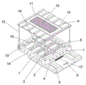
Fig. 1 is a schematic structural view of the present invention;
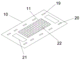
fig. 2 is a schematic bottom structure view of the top cover of the present invention.
In the figure: the battery box comprises a battery box 1, a transverse partition plate 2, an installation base 3, a sliding strip 4, a movable groove 5, an installation hole 6, a wiring hole 7, a battery placing groove 8, a rubber strip 9, a top cover 10, a first fan box 11, an electric telescopic rod 12, a power switch 13, a heat dissipation hole 14, an air inlet hole 15, a longitudinal partition plate 16, a second fan box 17, a rubber block 18, a temperature sensor 19, a humidity sensor 20, an LED lamp panel 21 and an exhaust hole 22.
Detailed Description
The following detailed description of the preferred embodiments of the present invention will be provided in conjunction with the accompanying drawings, so that the advantages and features of the present invention can be more easily understood by those skilled in the art, and the protection scope of the present invention can be clearly and clearly defined.
Example (b): referring to fig. 1-2, the present invention provides a technical solution: a lithium battery heat dissipation mounting structure for a new energy automobile comprises a battery box 1, a plurality of battery placing grooves 8 are arranged in the battery box 1, transverse partition plates 2 are arranged on two sides of each battery placing groove 8, a longitudinal partition plate 16 is arranged at one end of each transverse partition plate 2, a plurality of rubber blocks 18 are arranged on the inner side of the battery box 1 and two sides of each transverse partition plate 2, a wiring hole 7 is arranged on one side of each rubber block 18, a plurality of heat dissipation holes 14 are arranged on two sides of the battery box 1 and the longitudinal partition plates 16, sliding strips 4 are arranged on two sides of the bottom of the battery box 1, a movable groove 5 is arranged at the bottom of each sliding strip 4, a mounting base 3 is arranged at the bottom of each movable groove 5, a plurality of mounting holes 6 are arranged on the mounting base 3, a second fan box 17 is arranged at one end of the bottom of the battery box 1, electric telescopic rods 12 are arranged at four corners of the battery box 1, and a top cover 10 is arranged at the top of each electric telescopic rod 12, the middle part of top cap 10 installs first fan case 11, the top of first fan case 11 is equipped with a plurality of fresh air inlet 15, a plurality of hole 22 of airing exhaust is installed to the bottom of first fan case 11, LED lamp plate 21 is all installed at the bottom both ends of first fan case 11, a plurality of temperature sensor 19 is installed to bottom one side of first fan case 11, a plurality of humidity transducer 20 is installed to the bottom opposite side of first fan case 11, a plurality of rubber strip 9 is installed at the top of top cap 10, switch 13 is installed in the outside of battery box 1.
The bottom of electric telescopic handle 12 is passed through the bolt and is installed in four corners of battery box 1, and top cap 10 passes through the bolt and installs on the top of electric telescopic handle 12, can open automatically and closed top cap 10 through electric telescopic handle 12, need not the manpower.
The rubber blocks 18 are regularly distributed on the inner side of the battery box 1 and the two sides of the transverse partition plates 2, the heat dissipation holes 14 are regularly distributed on the two sides of the battery box 1 and the two sides of the longitudinal partition plates 16, the bottom of the battery placing groove 8 is in a hollow-out state, the rubber blocks 18 are installed to have a buffering effect, collision is avoided, and the storage battery is damaged.
Switch 13 links to each other with external power cord electrical property, switch 13 respectively with electric telescopic handle 12, temperature sensor 19, humidity transducer 20 and LED lamp plate 21 electrical property link to each other, and temperature sensor 19 and humidity transducer 20 all link to each other through the fan electrical property in controller and first fan case 11 and the second fan case 17, and installation switch 13 can control electric telescopic handle 12, temperature sensor 19, humidity transducer 20 and LED lamp plate 21, makes their braking.
The working principle is as follows: a lithium battery heat dissipation mounting structure for a new energy automobile comprises a battery box 1, a transverse partition plate 2, a mounting base 3, a slide bar 4, a movable groove 5, a mounting hole 6, a wiring hole 7, a battery placing groove 8, a rubber strip 9, a top cover 10, a first fan box 11, an electric telescopic rod 12, a power switch 13, a heat dissipation hole 14, an air inlet hole 15, a longitudinal partition plate 16, a second fan box 17, rubber blocks 18, a temperature sensor 19, a humidity sensor 20, an LED lamp panel 21 and an air exhaust hole 22, wherein a storage battery is placed on the battery placing groove 8 in the battery box 1, the storage battery can be protected against impact by mounting a plurality of rubber blocks 18, the battery is prevented from loosening caused by bumping and colliding, the battery is damaged, the buffering effect is good, the power supply of the temperature sensor 19 is switched on, when the internal temperature exceeds a set temperature, the temperature sensor 19 controls the fans in the first fan box 11 and the second fan box 17 to brake through a controller, carry out the heat dissipation work to inside battery, switch-on humidity transducer 20's power, when inside humidity exceeded when setting for numerical value, humidity transducer 20 passed through the fan braking in first fan case 11 of controller control and the second fan case 17, carry out the work of hydrofuge, switch-on electric telescopic handle 12 and LED lamp plate 21's power, it is closed to stretch out and draw back through electric telescopic handle 12 and drive top cap 10 automation, conveniently overhaul and change the battery, will install base 3 through the bolt and fix in the car, rethread draw runner 4 is fixed battery box 1 and movable slot 5 on the installation base 3, make it be convenient for install and dismantle, improve people's maintenance or change efficiency.
The structure has the buffer effect, the storage batteries cannot be loosened, the mutual collision is avoided, and the batteries are protected from being damaged by collision; the structure has an automatic heat dissipation function, and meanwhile, the humidity can be automatically discharged, so that the service life of the storage battery is prolonged;
the seal cover of the structure can be automatically opened, so that time and labor are saved, and the storage battery is convenient to overhaul and replace; this structure is through setting up draw runner and activity groove, can follow the car inside pull-out with the battery case and come out, and the staff of being convenient for installs and dismantles the battery, improves people's maintenance or change efficiency.
The above examples only show some embodiments of the present invention, and the description thereof is more specific and detailed, but not to be construed as limiting the scope of the invention. It should be noted that, for those skilled in the art, without departing from the spirit of the present invention, several variations and modifications can be made, which are within the scope of the present invention.
Claims (6)
1. The utility model provides a lithium cell heat dissipation mounting structure for new energy automobile, includes battery box (1), its characterized in that: the battery box is characterized in that a plurality of battery placing grooves (8) are arranged in the battery box (1), transverse partition plates (2) are arranged on two sides of each battery placing groove (8), a longitudinal partition plate (16) is arranged at one end of each transverse partition plate (2), a plurality of rubber blocks (18) are arranged on the inner side of the battery box (1) and two sides of each transverse partition plate (2), a wiring hole (7) is formed in one side of each rubber block (18), a plurality of radiating holes (14) are formed in two sides of the battery box (1) and the longitudinal partition plates (16), sliding strips (4) are arranged on two sides of the bottom of the battery box (1), movable grooves (5) are formed in the bottoms of the sliding strips (4), an installation base (3) is arranged at the bottom of each movable groove (5), a plurality of installation holes (6) are formed in the installation base (3), and a second fan box (17) is arranged at one end of the bottom of the battery box (1), electric telescopic handle (12) are all installed to four corners of battery box (1), top cap (10) are installed at the top of electric telescopic handle (12), the mid-mounting of top cap (10) has first fan case (11), the top of first fan case (11) is equipped with a plurality of fresh air inlet (15), a plurality of hole (22) of airing exhaust is installed to the bottom of first fan case (11), LED lamp plate (21) are all installed at the bottom both ends of first fan case (11), a plurality of temperature sensor (19) are installed to bottom one side of first fan case (11), a plurality of humidity transducer (20) are installed to the bottom opposite side of first fan case (11), a plurality of rubber strip (9) are installed at the top of top cap (10), switch (13) are installed in the outside of battery box (1).
2. The lithium battery heat dissipation mounting structure for the new energy automobile of claim 1, characterized in that: the bottom of electric telescopic handle (12) passes through the bolt and installs four corners in battery box (1), top cap (10) pass through the bolt and install on the top of electric telescopic handle (12).
3. The lithium battery heat dissipation mounting structure for the new energy automobile of claim 1, characterized in that: first fan case (11) pass through the bolt and install in the middle part of top cap (10), LED lamp plate (21) pass through the bolt and install in the bottom of top cap (10), rubber strip (9) regular distribution is in on the top of top cap (10).
4. The lithium battery heat dissipation mounting structure for the new energy automobile of claim 1, characterized in that: the rubber blocks (18) are regularly distributed on the inner side of the battery box (1) and the two sides of the transverse partition plates (2), the heat dissipation holes (14) are regularly distributed on the two sides of the battery box (1) and the two sides of the longitudinal partition plates (16), and the bottom of the battery placement groove (8) is in a hollow state.
5. The lithium battery heat dissipation mounting structure for the new energy automobile of claim 1, characterized in that: temperature sensor (19) and humidity transducer (20) all pass through the bolt and install on the bottom of top cap (10), switch (13) pass through the bolt and install on the outside of battery box (1), second fan case (17) pass through the bolt and install the bottom one end at battery box (1), battery box (1) pass through draw runner (4) and link to each other with activity groove (5) activity.
6. The lithium battery heat dissipation mounting structure for the new energy automobile of claim 1, characterized in that: switch (13) link to each other with external power cord electrical property, switch (13) link to each other with electric telescopic handle (12), temperature sensor (19), humidity transducer (20) and LED lamp plate (21) electrical property respectively, temperature sensor (19) and humidity transducer (20) all link to each other with the fan electrical property in first fan case (11) and second fan case (17) through the controller.
Priority Applications (1)
| Application Number | Priority Date | Filing Date | Title |
|---|---|---|---|
| CN202120711482.7U CN215184301U (en) | 2021-04-08 | 2021-04-08 | Lithium battery heat dissipation mounting structure for new energy automobile |
Applications Claiming Priority (1)
| Application Number | Priority Date | Filing Date | Title |
|---|---|---|---|
| CN202120711482.7U CN215184301U (en) | 2021-04-08 | 2021-04-08 | Lithium battery heat dissipation mounting structure for new energy automobile |
Publications (1)
| Publication Number | Publication Date |
|---|---|
| CN215184301U true CN215184301U (en) | 2021-12-14 |
Family
ID=79359479
Family Applications (1)
| Application Number | Title | Priority Date | Filing Date |
|---|---|---|---|
| CN202120711482.7U Expired - Fee Related CN215184301U (en) | 2021-04-08 | 2021-04-08 | Lithium battery heat dissipation mounting structure for new energy automobile |
Country Status (1)
| Country | Link |
|---|---|
| CN (1) | CN215184301U (en) |
-
2021
- 2021-04-08 CN CN202120711482.7U patent/CN215184301U/en not_active Expired - Fee Related
Similar Documents
| Publication | Publication Date | Title |
|---|---|---|
| CN206685765U (en) | A kind of fixed regulator cubicle of outdoor | |
| CN212011833U (en) | Self-heat dissipation device of box-type substation | |
| CN215184301U (en) | Lithium battery heat dissipation mounting structure for new energy automobile | |
| CN202603129U (en) | Machine cabinet radiation system | |
| CN110364945B (en) | Protection type outdoor distribution box | |
| CN216868677U (en) | Idle call heat abstractor | |
| CN214176448U (en) | Water and electricity is dehydrating unit for cabinet | |
| CN200967401Y (en) | Solar energy semiconductor air conditioner for driving stations | |
| CN209963598U (en) | Power transformation equipment with moisture-proof structure for power communication | |
| CN208411881U (en) | It is a kind of with the agricultural machinery mud guard for quickly removing mud | |
| CN112489947A (en) | Multifunctional automatic transformer | |
| CN113285151A (en) | Lead-acid battery safety charging equipment | |
| CN215378056U (en) | High-low voltage comprehensive power distribution cabinet | |
| CN212991206U (en) | Battery box with heat dissipation function and electric forklift thereof | |
| CN219874610U (en) | Medium-voltage switch cabinet for realizing equipment interlocking integration | |
| CN113465077B (en) | Pig feed processing factory ventilation system | |
| CN217608188U (en) | Outdoor communication box based on dismouting | |
| CN216086163U (en) | Automatic voltage regulator for circuit | |
| CN216414919U (en) | High frequency power control box components of a whole that can function independently heat radiation structure | |
| CN216437645U (en) | Smart management device for microgrid | |
| CN210628800U (en) | Low-voltage switch cabinet convenient to increase and decrease components and parts | |
| CN218858214U (en) | Intelligent battery replacement cabinet | |
| CN219643354U (en) | Energy-saving high-low voltage power distribution cabinet equipment | |
| CN220830239U (en) | Preassembled transformer substation capable of saving energy consumption | |
| CN215772772U (en) | Electric actuator with high-efficient heat dissipation function |
Legal Events
| Date | Code | Title | Description |
|---|---|---|---|
| GR01 | Patent grant | ||
| GR01 | Patent grant | ||
| CF01 | Termination of patent right due to non-payment of annual fee |
Granted publication date: 20211214 |