CN215151352U - Novel injection mold with water cooling effect - Google Patents
Novel injection mold with water cooling effect Download PDFInfo
- Publication number
- CN215151352U CN215151352U CN202120999200.8U CN202120999200U CN215151352U CN 215151352 U CN215151352 U CN 215151352U CN 202120999200 U CN202120999200 U CN 202120999200U CN 215151352 U CN215151352 U CN 215151352U
- Authority
- CN
- China
- Prior art keywords
- cooling
- water
- injection mold
- template
- cover half
- Prior art date
- Legal status (The legal status is an assumption and is not a legal conclusion. Google has not performed a legal analysis and makes no representation as to the accuracy of the status listed.)
- Active
Links
Images


Abstract
The utility model discloses a novel injection mold with water cooling effect, which comprises a demoulding mechanism, a movable mold base plate, a supporting seat, a fixed connecting plate, a sleeve cooling device, a movable mold plate, an injection port, a fixed mold base plate, a fixed mold plate, a water inlet, a connecting sleeve, a connecting pipe, a water outlet and a capillary cooling pipe, wherein the sleeve cooling device is additionally arranged on the injection mold, when the injection mold is used, the sleeve cooling device can be connected with an external circulating cooling water source through the water inlet and the water outlet, at the moment, when the injection mold performs injection molding processing, cooling water can enter the connecting pipe through the water inlet, thereby entering the capillary cooling pipe, and the capillary cooling pipe is contacted with a forming inner mold, so that the heat generated by the injection molding of the forming inner mold can be taken away by the circulating cooling water in the capillary cooling pipe, and then the circulating cooling water with heat can be discharged from the water outlet, therefore, heat generated during the operation of the injection mold can be taken away in time, and the use performance of the injection mold is improved.
Description
Technical Field
The utility model belongs to the technical field of injection mold is relevant, concretely relates to novel injection mold who has water-cooling effect.
Background
Injection molding is a method for producing moldings from industrial products, which generally use rubber injection molding and plastic injection molding. The injection molding can be divided into injection molding and die casting, an injection molding machine (an injection machine or an injection molding machine for short) is a main molding device for making thermoplastic plastics or thermosetting materials into plastic products with various shapes by using a plastic molding die, and the injection molding is realized by the injection molding machine and the die.
The existing injection mold technology has the following problems: the injection molding process generally extrudes hot-melted plastic into a die with a corresponding shape for die-casting molding during molding, the temperature of raw materials in a hot-melting state is high, the temperature of the die can be increased due to heat, the molding speed of the raw materials can be influenced by the die with the high temperature, the molded materials are not easy to cool and mold, and therefore the injection molding efficiency is influenced.
SUMMERY OF THE UTILITY MODEL
An object of the utility model is to provide a novel injection mold who has water-cooling effect to the heat that provides in solving above-mentioned background art can make the temperature of mould also rise, and the too high mould of temperature can lead to the fact the influence to the shaping speed of raw materials, can make the difficult cooling shaping of material after the shaping, thereby influences the problem of the efficiency of moulding plastics.
In order to achieve the above object, the utility model provides a following technical scheme: the utility model provides a novel injection mold with water-cooling effect, includes demoulding mechanism, movable mould bedplate, supporting seat, fixed connection board, cup joints cooling device, movable mould board, the mouth of moulding plastics, cover half bedplate, cover half template, water inlet, adapter sleeve, connecting pipe, delivery port and capillary cooling tube, the supporting seat is installed to the upper end of movable mould bedplate, the intermediate position department that movable mould bedplate upper end and lie in the supporting seat is provided with demoulding mechanism, be provided with fixed connection board on the upper end outer wall of supporting seat, be provided with the movable mould board on fixed connection board's the upper end outer wall, be provided with all around the movable mould board and cup joint cooling device, be provided with the cover half template on the upper end outer wall of movable mould board, be provided with the cover half bedplate on the upper end outer wall of cover half template, be provided with the mouth of moulding plastics on the upper end outer wall of cover half bedplate.
Preferably, the sleeve-joint cooling device comprises a water inlet, a connecting sleeve, a connecting pipe, a water outlet and a capillary cooling pipe, the connecting sleeve is sleeved at the front end of the connecting pipe, the water inlet is formed in the left side of the connecting sleeve, the water outlet is formed in the right side of the connecting sleeve, and the capillary cooling pipe is arranged on the inner wall of the connecting pipe.
Preferably, the connecting pipe is of a hollow structure, the connecting pipe is communicated with the movable die plate, the sleeve-joint cooling device is embedded into the movable die plate through the connecting pipe and arranged at the periphery of the movable die plate, and the connecting pipe is connected with the movable die plate in an interference fit mode.
Preferably, the position of the inner upper end of the movable die plate is provided with a forming inner die, the position of the inner lower end of the fixed die plate is also provided with a forming inner die, and the outer wall of the lower end of the fixed die plate and the outer wall of the upper end of the movable die plate can be completely attached.
Preferably, the movable die template is provided with a groove at the position of the connecting pipe, the inside of the groove is provided with an insertion hole corresponding to the capillary cooling pipe, the inner diameter of the insertion hole is equal to the outer diameter of the capillary cooling pipe, the end of the capillary cooling pipe is in a sealing state, and the end of the capillary cooling pipe is in contact with the forming internal die.
Preferably, a connector is arranged in the fixed die base plate, and the inner diameter of the injection molding opening is the same as that of the connector.
Compared with the prior art, the utility model provides a novel injection mold with water-cooling effect possesses following beneficial effect:
the utility model adds the sleeve cooling device on the injection mould, the sleeve cooling device is composed of a water inlet, a connecting sleeve, a connecting pipe, a water outlet and a capillary cooling pipe, when the injection mould is used, the sleeve cooling device can be connected with an external circulating cooling water source through the water inlet and the water outlet, at the time, when the injection mould carries out injection molding processing, cooling water can enter the inside of the connecting pipe through the water inlet, thereby entering the inside of the capillary cooling pipe, and the capillary cooling pipe is contacted with the forming inner mould, so that the heat generated by the injection molding of the forming inner mould can be taken away by the circulating cooling water in the capillary cooling pipe, and then the circulating cooling water with heat can be discharged from the water outlet, thereby the heat generated when the injection mould works can be taken away in time, and the influence on the quality and the efficiency of the injection molding when the heat in the injection mould is not dissipated in time is avoided, the use performance of the injection mold is improved.
Drawings
The accompanying drawings are included to provide a further understanding of the invention, and are incorporated in and constitute a part of this specification, illustrate embodiments of the invention, and together with the description, do not constitute a limitation of the invention, in which:
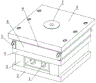
FIG. 1 is a schematic view of a novel injection mold with water cooling function according to the present invention;
FIG. 2 is a schematic view of a front structure of a novel injection mold with water cooling function provided by the present invention;
FIG. 3 is a schematic side view of a novel injection mold with water cooling function according to the present invention;
fig. 4 is a schematic structural view of the main body of the sleeved cooling device provided by the present invention;
in the figure: 1. a demoulding mechanism; 2. a movable mould seat plate; 3. a supporting seat; 4. fixing the connecting plate; 5. sleeving a cooling device; 6. moving the die plate; 7. an injection molding port; 8. a fixed die base plate; 9. fixing a mould plate; 10. a water inlet; 11. connecting sleeves; 12. a connecting pipe; 13. a water outlet; 14. a capillary cooling tube.
Detailed Description
The technical solutions in the embodiments of the present invention will be described clearly and completely with reference to the accompanying drawings in the embodiments of the present invention, and it is obvious that the described embodiments are only some embodiments of the present invention, not all embodiments. Based on the embodiments in the present invention, all other embodiments obtained by a person skilled in the art without creative work belong to the protection scope of the present invention.
The first embodiment is as follows:
referring to fig. 1, fig. 2 and fig. 3, the present invention provides a technical solution: a novel injection mold with water cooling effect comprises a demoulding mechanism 1, a movable mold base plate 2, a supporting seat 3, a fixed connecting plate 4, a sleeving cooling device 5, a movable mold plate 6, an injection port 7, a fixed mold base plate 8, a fixed mold plate 9, a water inlet 10, a connecting sleeve 11, a connecting pipe 12, a water outlet 13 and a capillary cooling pipe 14, wherein the supporting seat 3 is installed at the upper end of the movable mold base plate 2, the demoulding mechanism 1 is arranged at the upper end of the movable mold base plate 2 and is positioned at the middle position of the supporting seat 3, the specific demoulding mode of the demoulding mechanism 1 is the prior art, so that the technical document does not need to describe much details, the fixed connecting plate 4 is arranged on the outer wall of the upper end of the supporting seat 3, the movable mold plate 6 is arranged on the outer wall of the upper end of the fixed connecting plate 4, the sleeving cooling device 5 is arranged around the movable mold plate 6, the fixed mold plate 9 is arranged on the outer wall of the upper end of the movable mold plate 6, be provided with cover half bedplate 8 on the upper end outer wall of cover half template 9, be provided with the mouth of moulding plastics 7 on the upper end outer wall of cover half bedplate 8, the inside upper end position department on the upper side of movable mould template 6 is provided with the shaping centre form, the inside lower end position department on the lower side of cover half template 9 also is provided with the shaping centre form, the lower extreme outer wall of cover half template 9 and the upper end outer wall of movable mould template 6 can laminate completely, the inside of cover half bedplate 8 is provided with the connector, the internal diameter size of the mouth of moulding plastics 7 is the same with the internal diameter size of connector.
Example two:
referring to fig. 1 and 4, the present invention provides a technical solution: a novel injection mold with water cooling function, a sleeve cooling device 5 is arranged around a movable mold plate 6, the sleeve cooling device 5 comprises a water inlet 10, a connecting sleeve 11, a connecting pipe 12, a water outlet 13 and a capillary cooling pipe 14, the connecting sleeve 11 is sleeved at the front end position of the connecting pipe 12, the left connecting sleeve 11 is provided with the water inlet 10, the right connecting sleeve 11 is provided with the water outlet 13, the inner wall of the connecting pipe 12 is provided with the capillary cooling pipe 14, the connecting pipe 12 is of a hollow structure, the connecting pipes 12 and 14 are in a communicated state, the sleeve cooling device 5 is embedded and arranged at the peripheral position of the movable mold plate 6 through the connecting pipe 12, the connecting pipe 12 is in interference fit connection with the movable mold plate 6, the movable mold plate 6 is provided with a groove at the position of the connecting pipe 12, the inside of the groove is provided with a jack corresponding to the capillary cooling pipe 14, and the inner diameter of the jack is equal to the outer diameter of the capillary cooling pipe 14, the end of the capillary cooling pipe 14 is in a sealed state, and the end of the capillary cooling pipe 14 is in contact with the forming internal mold, when the injection mold is used, the sleeved cooling device 5 can be connected with an external circulating cooling water source through the water inlet 10 and the water outlet 13, at this time, when the injection mold performs injection molding, cooling water can enter the inside of the connecting pipe 12 through the water inlet 10, so that the cooling water enters the inside of the capillary cooling pipe 14, and the capillary cooling pipe 14 is in contact with the forming internal mold, so that the heat generated by injection molding of the forming internal mold can be taken away by the cooling water circulating inside the capillary cooling pipe 14, and then the circulating cooling water with the heat can be discharged from the water outlet 13, so that the heat generated during working of the injection mold can be taken away in time.
The utility model discloses a theory of operation and use flow: the utility model discloses install the back, this novel injection mold with water-cooling structure's principle is that the material that will be heated and melt is by in 7 high pressures jets into the shaping centre forms of movable mould template 6 and cover half template 9 through the mouth of moulding plastics, after the cooling solidification, obtain the shaping article, movable mould template 6 is installed on injection moulding machine's movable mould board through movable mould die holder 2, cover half template 9 is installed on injection moulding machine's fixed die plate through cover half die holder 8, movable mould template 6 and cover half template 9 closure constitute gating system and shaping centre form when injection moulding, movable mould template 6 and cover half template 9 separate so that take out plastic products during the die sinking.
Although embodiments of the present invention have been shown and described, it will be appreciated by those skilled in the art that changes, modifications, substitutions and alterations can be made in these embodiments without departing from the principles and spirit of the invention, the scope of which is defined in the appended claims and their equivalents.
Claims (6)
1. The utility model provides a novel injection mold with water-cooling effect, includes demoulding mechanism (1), movable mould bedplate (2), supporting seat (3), fixed connection board (4), cup joints cooling device (5), movable mould template (6), mouth (7) of moulding plastics, cover half bedplate (8), cover half template (9), water inlet (10), adapter sleeve (11), connecting pipe (12), delivery port (13) and capillary cooling tube (14), its characterized in that: supporting seat (3) are installed to the upper end of movable mould bedplate (2), the intermediate position department that movable mould bedplate (2) upper end and lie in supporting seat (3) is provided with demoulding mechanism (1), be provided with fixed connection board (4) on the upper end outer wall of supporting seat (3), be provided with movable mould board (6) on the upper end outer wall of fixed connection board (4), be provided with all around of movable mould board (6) and cup joint cooling device (5), be provided with cover half template (9) on the upper end outer wall of movable mould board (6), be provided with cover half bedplate (8) on the upper end outer wall of cover half template (9), be provided with on the upper end outer wall of cover half bedplate (8) and mould plastics mouthful (7).
2. The novel injection mold with water cooling function as claimed in claim 1, wherein: cup joint cooling device (5) and include water inlet (10), adapter sleeve (11), connecting pipe (12), delivery port (13) and capillary cooling tube (14), adapter sleeve (11) cup joints the front position department in connecting pipe (12), the left side be provided with water inlet (10), right side on adapter sleeve (11) be provided with delivery port (13) on adapter sleeve (11), be provided with capillary cooling tube (14) on the inner wall of connecting pipe (12).
3. The novel injection mold with water cooling function as claimed in claim 2, wherein: the connecting pipe (12) is of a hollow structure, the connecting pipes (12) and (14) are in a communicated state, the sleeve-joint cooling device (5) is embedded into the positions around the movable die template (6) through the connecting pipes (12), and the connecting pipes (12) are connected with the movable die template (6) in an interference fit mode.
4. The novel injection mold with water cooling function as claimed in claim 1, wherein: the inside upper end position department on the contrary of movable mould template (6) is provided with the shaping centre form, the inside lower end position department on the contrary of cover half template (9) also is provided with the shaping centre form, the lower extreme outer wall of cover half template (9) and the upper end outer wall of movable mould template (6) can laminate completely.
5. The novel injection mold with water cooling function as claimed in claim 1, wherein: the movable die template (6) is provided with a groove at the position of the connecting pipe (12), the inside of the groove is provided with an inserting hole corresponding to the capillary cooling pipe (14), the inner diameter of the inserting hole is equal to the outer diameter of the capillary cooling pipe (14), the end of the capillary cooling pipe (14) is in a sealing state, and the end of the capillary cooling pipe (14) is in contact with the forming internal die.
6. The novel injection mold with water cooling function as claimed in claim 1, wherein: the inside of cover half bedplate (8) is provided with the connector, the internal diameter size of mouth (7) of moulding plastics is the same with the internal diameter size of connector.
Priority Applications (1)
| Application Number | Priority Date | Filing Date | Title |
|---|---|---|---|
| CN202120999200.8U CN215151352U (en) | 2021-05-11 | 2021-05-11 | Novel injection mold with water cooling effect |
Applications Claiming Priority (1)
| Application Number | Priority Date | Filing Date | Title |
|---|---|---|---|
| CN202120999200.8U CN215151352U (en) | 2021-05-11 | 2021-05-11 | Novel injection mold with water cooling effect |
Publications (1)
| Publication Number | Publication Date |
|---|---|
| CN215151352U true CN215151352U (en) | 2021-12-14 |
Family
ID=79368568
Family Applications (1)
| Application Number | Title | Priority Date | Filing Date |
|---|---|---|---|
| CN202120999200.8U Active CN215151352U (en) | 2021-05-11 | 2021-05-11 | Novel injection mold with water cooling effect |
Country Status (1)
| Country | Link |
|---|---|
| CN (1) | CN215151352U (en) |
-
2021
- 2021-05-11 CN CN202120999200.8U patent/CN215151352U/en active Active
Similar Documents
| Publication | Publication Date | Title |
|---|---|---|
| CN215434896U (en) | Injection molding mold for automobile door handle | |
| CN214419428U (en) | Automobile injection mold with external cooling system | |
| CN215151352U (en) | Novel injection mold with water cooling effect | |
| CN210758865U (en) | Quick forming die of electric bicycle's shell covering | |
| CN213137622U (en) | Shaping die for splash-proof mask | |
| CN211416101U (en) | Mould core with demoulding device | |
| CN210969741U (en) | Plastic mould with insert pin water-cooling structure | |
| CN212579097U (en) | Anti-leakage injection mold | |
| CN214820656U (en) | Purifier front cover mould | |
| CN216267305U (en) | Integrated electric drill shell high-precision injection mold | |
| CN112339234A (en) | Injection mold cooling system convenient for demolding | |
| CN212472103U (en) | Pipeline type plastic mould capable of being cooled rapidly | |
| CN213618062U (en) | Mould of modular elbow production usefulness | |
| CN210705888U (en) | Injection mold with cooling function | |
| CN213500583U (en) | Injection mold for producing injection molding product with good sealing performance | |
| CN220614785U (en) | Liquid cooling structure of one-die multi-cavity precision injection mold | |
| CN213260942U (en) | Injection moulding's quick plastic mold of electroplating | |
| CN210969723U (en) | Be used for high accuracy to produce plastic mould for a long time | |
| CN216329784U (en) | Hot runner injection molding device based on Internet of things communication base | |
| CN210634041U (en) | Injection mold | |
| CN213108073U (en) | Automobile sound equipment longitudinal panel mold structure based on 3D printing | |
| CN215969824U (en) | Ox horn injection mold for dustproof cover of electronic gear | |
| CN211440940U (en) | Multi-cavity injection mold | |
| CN216001410U (en) | Quick cooling mechanism of plastic uptake machine | |
| CN215095224U (en) | Injection mold for control panel of washing machine |
Legal Events
| Date | Code | Title | Description |
|---|---|---|---|
| GR01 | Patent grant | ||
| GR01 | Patent grant |