CN215148027U - Pipe polishing machine - Google Patents
Pipe polishing machine Download PDFInfo
- Publication number
- CN215148027U CN215148027U CN202121329121.2U CN202121329121U CN215148027U CN 215148027 U CN215148027 U CN 215148027U CN 202121329121 U CN202121329121 U CN 202121329121U CN 215148027 U CN215148027 U CN 215148027U
- Authority
- CN
- China
- Prior art keywords
- polishing
- base
- cavity
- polishing machine
- pipe polishing
- Prior art date
- Legal status (The legal status is an assumption and is not a legal conclusion. Google has not performed a legal analysis and makes no representation as to the accuracy of the status listed.)
- Expired - Fee Related
Links
- 238000005498 polishing Methods 0.000 title claims abstract description 57
- 239000000428 dust Substances 0.000 claims description 5
- 238000000034 method Methods 0.000 abstract description 3
- 238000007517 polishing process Methods 0.000 abstract description 3
- 238000004519 manufacturing process Methods 0.000 abstract description 2
- 244000309464 bull Species 0.000 description 5
- 230000000694 effects Effects 0.000 description 3
- 230000004075 alteration Effects 0.000 description 1
- 230000009286 beneficial effect Effects 0.000 description 1
- 239000004744 fabric Substances 0.000 description 1
- 230000001771 impaired effect Effects 0.000 description 1
- 238000012986 modification Methods 0.000 description 1
- 230000004048 modification Effects 0.000 description 1
- 230000001737 promoting effect Effects 0.000 description 1
- 238000003860 storage Methods 0.000 description 1
- 238000006467 substitution reaction Methods 0.000 description 1
- 238000003466 welding Methods 0.000 description 1
Images


Landscapes
- Finish Polishing, Edge Sharpening, And Grinding By Specific Grinding Devices (AREA)
Abstract
The utility model discloses a pipe polishing machine, which belongs to the technical field of polishing machines and comprises a base, a polishing table is connected above the base, one side of the base, which is close to the polishing table, is provided with a cavity, a collection box is arranged inside the cavity, a sliding plate is connected on the side wall of the collection box, a sliding groove is arranged on the side wall of the cavity and at the position corresponding to the sliding plate, one end of the sliding plate is connected with a limiting plate, the limiting plate is connected with the base through a first bolt, an exhaust fan is arranged inside the collection box, and an opening is arranged on the polishing table and corresponding to the output end of the exhaust fan; the utility model discloses the below of polishing platform in original tubular product burnishing machine adds the clastic collection device who collects the in-process production of polishing, in polishing process, can collect the piece that produces through collecting the subassembly, need artifically clear up the piece after avoiding operating the completion and collect, has alleviateed staff's work burden.
Description
Technical Field
The utility model belongs to the technical field of the burnishing machine, concretely relates to tubular product burnishing machine.
Background
The polisher is an electric tool and consists of basic elements such as a base, a polishing disc, a polishing fabric, a polishing cover and a cover.
Chinese patent application No. 201920599820.5 discloses a high-efficient burnishing machine, including the polishing platform, the riser has all been welded to the both sides at polishing bench top, the surface of riser inlays and is equipped with the thread bush, the inside screw bull stick that runs through of thread bush is provided with, the one end welding of screw bull stick has adjust knob, adjust knob's one end is kept away from to the screw bull stick has the grip block through bearing frame fixed mounting, one side bolt that the thread bull stick was kept away from to the grip block has the concave surface polishing piece. The utility model discloses a setting of polishing platform, riser, thread bush, screw bull stick, adjust knob, grip block, concave surface polishing piece, hydraulic stem, driving motor and three-jaw (holding) chuck has solved present burnishing machine and when polishing tubular product articles for use, mostly all is through single polishing dish operation, along with the removal of tubular product realizes the polishing effect to whole tubular product, the problem of comparatively low efficiency, this high-efficient burnishing machine possesses the advantage that a plurality of polishing dishes and polishing efficiency are high, is worth promoting.
The above patent has the following problems: 1. debris is generated in the polishing process, and the debris needs to be cleaned and collected manually after the operation is finished, so that the labor burden of workers is increased; 2. when the device needs to be moved, the device needs to be manually carried or carried by means of an external carrying tool, so that the device is inconvenient to move.
SUMMERY OF THE UTILITY MODEL
To solve the problems set forth in the background art described above. The utility model provides a pipe polishing machine has the characteristics of conveniently clearing up the piece, conveniently removing.
In order to achieve the above object, the utility model provides a following technical scheme: the utility model provides a pipe polishing machine, includes the base, the top of base is connected with the polishing platform, one side that the base is close to the polishing platform is provided with the cavity, the inside of cavity is provided with collects the box, be connected with the slide on collecting the lateral wall of box, the position department that just corresponds the slide on the lateral wall of cavity is provided with the spout, the one end of slide is connected with the limiting plate, through first bolted connection between limiting plate and the base, the internally mounted of collecting the box has the air exhauster, the last output that just corresponds the air exhauster of polishing platform is provided with the opening, polishing assembly is installed to the top of polishing platform.
Preferably, the upper portion that just is located the air exhauster on the inside wall of collecting the box is connected with fixed frame, the top of fixed frame is provided with the installing frame, the internal connection of installing frame has the dust screen, pass through second bolted connection between installing frame and the fixed frame.
Preferably, a handle is connected to the side wall of the collecting box.
Preferably, the gyro wheel is installed to the below of base, be connected with the diaphragm on the lateral wall of base, be connected with the thread bush on the diaphragm, the internal connection of thread bush has the threaded rod, the one end of threaded rod is connected with the fixing base, the other end of threaded rod is connected with the knob.
Preferably, a rubber pad is sleeved on the periphery of the knob.
Preferably, a non-slip mat is connected below the roller.
Compared with the prior art, the beneficial effects of the utility model are that:
1. the utility model discloses the below of polishing platform in original tubular product burnishing machine adds the clastic collection device who collects the in-process production of polishing, in polishing process, can collect the piece that produces through collecting the subassembly, need artifically clear up the piece after avoiding operating the completion and collect, has alleviateed staff's work burden.
2. The utility model discloses the below of polishing platform in original tubular product burnishing machine adds the removal subassembly, when needs remove whole device, can directly remove whole device through removing the subassembly, avoids needing artifical transport or carries with the help of external handling tool, facilitates the removal of device.
Drawings
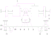
Fig. 1 is a schematic structural view of the present invention;
FIG. 2 is an enlarged view of the point A in FIG. 1 according to the present invention;
FIG. 3 is a sectional view showing a state where the polishing table of the present invention is connected to the base;
fig. 4 is an enlarged view of the point B in fig. 3 according to the present invention.
In the figure: 1. a polishing assembly; 2. a polishing table; 3. a rubber pad; 4. a threaded rod; 5. a fixed seat; 6. a roller; 7. a collection box; 8. a handle; 9. a cavity; 10. a base; 11. a non-slip mat; 12. a threaded sleeve; 13. a transverse plate; 14. a first bolt; 15. a limiting plate; 16. a chute; 17. a slide plate; 18. an opening; 19. a knob; 20. an exhaust fan; 21. a dust screen; 22. a second bolt; 23. installing a frame; 24. a fixing frame is provided.
Detailed Description
The technical solutions in the embodiments of the present invention will be described clearly and completely with reference to the accompanying drawings in the embodiments of the present invention, and it is obvious that the described embodiments are only some embodiments of the present invention, not all embodiments. Based on the embodiments in the present invention, all other embodiments obtained by a person skilled in the art without creative work belong to the protection scope of the present invention.
Referring to fig. 1-4, the present invention provides the following technical solutions: the utility model provides a pipe polishing machine, the on-line screen storage device comprises a base 10, the top of base 10 is connected with polishing platform 2, one side that base 10 is close to polishing platform 2 is provided with cavity 9, the inside of cavity 9 is provided with collects box 7, be connected with slide 17 on collecting box 7's the lateral wall, just the position department that corresponds slide 17 on cavity 9's the lateral wall is provided with spout 16, slide 17's one end is connected with limiting plate 15, be connected through first bolt 14 between limiting plate 15 and the base 10, the internally mounted of collecting box 7 has air exhauster 20, the output that just corresponds air exhauster 20 on the polishing platform 2 is provided with opening 18, polishing assembly 1 is installed to the top of polishing platform 2.
Specifically, a fixed frame 24 is connected on the inner side wall of the handle 8 and above the exhaust fan 20, a mounting frame 23 is arranged above the fixed frame 24, a dust screen 21 is connected inside the mounting frame 23, the mounting frame 23 is connected with the fixed frame 24 through a second bolt 22,
through adopting above-mentioned technical scheme, under the effect of dust screen 21, can avoid the piece to enter into inside air exhauster 20, cause air exhauster 20 impaired.
In particular, a handle 8 is connected on the side wall of the collecting box 7,
through adopting above-mentioned technical scheme, make things convenient for pull collection box 7.
Specifically, a roller 6 is arranged below a base 10, a transverse plate 13 is connected on the side wall of the base 10, a threaded sleeve 12 is connected on the transverse plate 13, a threaded rod 4 is connected inside the threaded sleeve 12, one end of the threaded rod 4 is connected with a fixed seat 5, the other end of the threaded rod 4 is connected with a knob 19,
through adopting above-mentioned technical scheme, conveniently remove or stably place whole device.
Specifically, the periphery of the knob 19 is sleeved with the rubber pad 3,
through adopting above-mentioned technical scheme, avoid using knob 19 in-process, the phenomenon of skidding takes place between hand and the knob 19.
Specifically, the lower part of the roller 6 is connected with a non-slip mat 11,
through adopting above-mentioned technical scheme, avoid in the use, take place the phenomenon of skidding between gyro wheel 6 and the ground.
The utility model discloses well structure of polishing subassembly and tubular product burnishing machine's theory of operation has disclosed in the high-efficient burnishing machine that chinese patent application number is 201920599820.5 discloses.
The utility model discloses a theory of operation and use flow: the utility model discloses after removing the device to service position department, rotate knob 19, thereby it rotates to drive threaded rod 4, thereby make threaded rod 4 descend in 12 rotations of thread bush, thereby drive fixing base 5 and descend, after fixing base 5 supports with ground, stop rotation knob 19, thereby make fixing base 5 rigidity, support whole device through fixing base 5, then place polishing table 2 on with the tubular product of treating processing, then start polishing subassembly 1 and air exhauster 20, polishing subassembly 1 polishes the tubular product, the piece that the polishing produced enters into in collection box 7 under air exhauster 20's effect, when the piece in collecting box 7 needs to be handled, take off first bolt 14, then take out collection box 7 from cavity 9, again handle the piece in the collection box 7.
Although embodiments of the present invention have been shown and described, it will be appreciated by those skilled in the art that changes, modifications, substitutions and alterations can be made in these embodiments without departing from the principles and spirit of the invention, the scope of which is defined in the appended claims and their equivalents.
Claims (6)
1. A pipe polishing machine comprises a base (10), and is characterized in that: the top of base (10) is connected with polishing platform (2), one side that base (10) is close to polishing platform (2) is provided with cavity (9), the inside of cavity (9) is provided with collects box (7), be connected with slide (17) on the lateral wall of collecting box (7), the position department that just corresponds slide (17) on the lateral wall of cavity (9) is provided with spout (16), the one end of slide (17) is connected with limiting plate (15), be connected through first bolt (14) between limiting plate (15) and base (10), the internally mounted of collecting box (7) has air exhauster (20), the output that just corresponds air exhauster (20) on polishing platform (2) is provided with opening (18), polishing subassembly (1) is installed to the top of polishing platform (2).
2. The pipe polishing machine of claim 1, wherein: collect on the inside wall of box (7) and be located the top of air exhauster (20) and be connected with fixed frame (24), the top of fixed frame (24) is provided with installing frame (23), the internal connection of installing frame (23) has dust screen (21), be connected through second bolt (22) between installing frame (23) and fixed frame (24).
3. The pipe polishing machine of claim 1, wherein: the side wall of the collecting box (7) is connected with a handle (8).
4. The pipe polishing machine of claim 1, wherein: gyro wheel (6) are installed to the below of base (10), be connected with diaphragm (13) on the lateral wall of base (10), be connected with thread bush (12) on diaphragm (13), the internal connection of thread bush (12) has threaded rod (4), the one end of threaded rod (4) is connected with fixing base (5), the other end of threaded rod (4) is connected with knob (19).
5. The pipe polishing machine of claim 4, wherein: and a rubber pad (3) is sleeved on the periphery of the knob (19).
6. The pipe polishing machine of claim 4, wherein: and an anti-skid pad (11) is connected below the roller (6).
Priority Applications (1)
| Application Number | Priority Date | Filing Date | Title |
|---|---|---|---|
| CN202121329121.2U CN215148027U (en) | 2021-06-15 | 2021-06-15 | Pipe polishing machine |
Applications Claiming Priority (1)
| Application Number | Priority Date | Filing Date | Title |
|---|---|---|---|
| CN202121329121.2U CN215148027U (en) | 2021-06-15 | 2021-06-15 | Pipe polishing machine |
Publications (1)
| Publication Number | Publication Date |
|---|---|
| CN215148027U true CN215148027U (en) | 2021-12-14 |
Family
ID=79387082
Family Applications (1)
| Application Number | Title | Priority Date | Filing Date |
|---|---|---|---|
| CN202121329121.2U Expired - Fee Related CN215148027U (en) | 2021-06-15 | 2021-06-15 | Pipe polishing machine |
Country Status (1)
| Country | Link |
|---|---|
| CN (1) | CN215148027U (en) |
-
2021
- 2021-06-15 CN CN202121329121.2U patent/CN215148027U/en not_active Expired - Fee Related
Similar Documents
| Publication | Publication Date | Title |
|---|---|---|
| CN109746781B (en) | Automatic hardware plate grinding machine | |
| CN215148027U (en) | Pipe polishing machine | |
| CN218194195U (en) | Trimming device with dust removal assembly for plastic mold machining | |
| CN209850575U (en) | Part grinding device for intelligent manufacturing | |
| CN216371576U (en) | Environment-friendly railway track accessory grinding device with dust removal function | |
| CN211565475U (en) | Stainless steel hardware processing equipment | |
| CN210281743U (en) | Hardware processing device with scrap recovery function | |
| CN214519349U (en) | Grinding device is used in agricultural machinery production | |
| CN212683442U (en) | Hardware polisher | |
| CN211073112U (en) | Bearing outer surface polishing device for machining mechanical parts | |
| CN212706055U (en) | A rust cleaning device for machining | |
| CN210255468U (en) | Polishing device for hardware | |
| CN211639831U (en) | Hardware processing platform | |
| CN210550150U (en) | Polishing device for processing photoelectric converter | |
| CN219542721U (en) | Automobile parts processing is with frock of polishing | |
| CN216228372U (en) | Grinding device is used in processing of insert bearing ring | |
| CN220637480U (en) | Ash removal device for casting polishing | |
| CN220279184U (en) | Grinding mechanism for shoe material auxiliary material processing | |
| CN220074159U (en) | Auto-parts surface coping device | |
| CN217914405U (en) | Steel sheet grinding device is used in processing of pitch jar body | |
| CN221390161U (en) | Cylindrical grinding machine with uniform grinding | |
| CN220881903U (en) | Grinding device for processing | |
| CN211362982U (en) | Numerical control five-axis linkage bridge type stone cutting machine | |
| CN212886884U (en) | Water pipe rust cleaning equipment for hydraulic engineering | |
| CN221735614U (en) | Totally-enclosed shield type surface grinding machine |
Legal Events
| Date | Code | Title | Description |
|---|---|---|---|
| GR01 | Patent grant | ||
| GR01 | Patent grant | ||
| CF01 | Termination of patent right due to non-payment of annual fee |
Granted publication date: 20211214 |
|
| CF01 | Termination of patent right due to non-payment of annual fee |