Background
In clinical work, the transfer flat car is a frequently-used medical instrument, is mainly used for in-hospital transfer or examination, can conveniently transfer patients, does not need to lift the patients off a stretcher after the patients are moved to an examination table or a bed, only needs to withdraw the stretcher rod, and reduces pain of the patients when the patients are lifted off the stretcher.
In the prior art, a transfer flat car is provided, which comprises a transfusion rod besides a flat car main body, but a monitor is required to monitor in real time in the transfer process of some patients, the transfer flat car is not provided with a corresponding platform for placing the monitor, and the monitor is held by a nurse in the transfer process, so that the labor intensity of the nurse is increased, and the nurse resources are occupied; in addition, the monitor is held by manpower in the transfer process, the traveling speed between the transfer flat car and the medical care personnel is different, and the monitor pulls the wire harness to hurt the patient due to the fact that the length of the wire harness between the monitor and the patient is fixed; when the monitor is used in daily life, the cabinet body needs to be additionally arranged for placing the monitor, and the monitor is not suitable for narrow ward space; some nurses' practice is to place the monitor at will on transporting the flatcar bed and limited position, appears dropping easily in the quick transportation process, makes the instrument damage, delays treatment moreover.
The above is only for the purpose of assisting understanding of the technical solutions of the present application, and does not represent an admission that the above is prior art.
SUMMERY OF THE UTILITY MODEL
To the above-mentioned weak point that exists among the prior art, the utility model aims at providing a can fix the instrument and have the transportation flatcar of putting the thing function and use multi-functional supporter.
The utility model discloses a realize that the technical scheme that above-mentioned purpose adopted is: a multifunctional commodity shelf for a hospital transfer platform is horizontally erected above the tail of the transfer platform and comprises a commodity platform and a removable instrument fixing mechanism;
upright rods are arranged at four corners of the bottom of the object placing table, the lower ends of the upright rods are fixed on cross rods at two sides of the tail of the transfer platform through locking parts, a first cavity with two open sides and a second cavity with one open side are arranged in the object placing table, two movable pull plates are arranged in the first cavity, a drawer is arranged in the second cavity, one corner of the object placing table is provided with a transfusion rod jack, and two screw rods are arranged at the top of the object placing table;
the instrument fixing mechanism comprises a square frame and connecting rods connected to two opposite sides of the square frame, each connecting rod is bent outwards to form a fixing portion, each fixing portion is provided with a through hole, the through holes penetrate through the corresponding screw rods and are locked by nuts, and therefore the instrument fixing mechanism is connected with the object placing tables.
Furthermore, a plurality of storage lattices are arranged in the drawer.
Furthermore, the two drawing plates are mutually pulled out in a back-to-back mode.
Furthermore, two groups of sliding rails are respectively arranged on two side walls in the first cavity, one group of sliding rails is connected with two side edges of the pull plate, and the other group of sliding rails is connected with two side edges of the pull plate.
Further, the square frame and the connecting rod are both made of stainless steel materials.
Further, the square frame and the connecting rod are connected through welding.
Furthermore, the upright stanchion is connected with the object placing table through welding.
Furthermore, the object placing table is provided with guardrails on the periphery.
Furthermore, an elastic rubber mat is arranged on the inner side face of the square frame.
Further, the screw rod is connected with the object placing table through welding.
The utility model has the advantages that: the utility model discloses simple structure, the removal of being convenient for can all-round placing instrument and various article, prevents that the instrument from dropping and damaging, can place the supporter in the top of transporting flatcar afterbody during the use, does not account for the bed space, and in the transportation, the instrument need not the nurse and holds, reduces the manpower.
Detailed Description
The technical solutions in the embodiments of the present invention will be described clearly and completely with reference to the accompanying drawings in the embodiments of the present invention, and it is obvious that the described embodiments are only some embodiments of the present invention, not all embodiments. Based on the embodiments in the present invention, all other embodiments obtained by a person skilled in the art without creative work belong to the protection scope of the present invention.
Referring to fig. 1 to 3, the present invention provides a multifunctional rack for a hospital transfer platform.
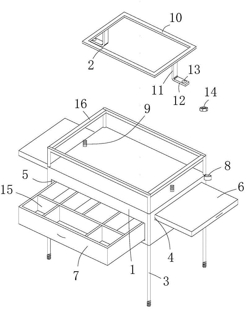
In the embodiment, the commodity shelf is horizontally erected above the tail part of the transfer platform and comprises a commodity platform 1 and a removable instrument fixing mechanism 2;
four corners of the bottom of the object placing table 1 are provided with vertical rods 3, the lower ends of the vertical rods 3 are fixed on cross rods on two sides of the tail of the transfer platform through locking parts, a first cavity 4 with two open sides and a second cavity 5 with one open side are arranged in the object placing table 1, two movable pull plates 6 are arranged in the first cavity 4, a drawer 7 is arranged in the second cavity 5, one corner of the object placing table 1 is provided with a transfusion rod jack 8, and the top of the object placing table 1 is provided with two screw rods 9;
instrument fixed establishment 2 includes square frame 10 and connects the connecting rod 11 in the relative both sides of square frame 10, each 11 tail ends of connecting rod outwards buckle and form a fixed part 12, each through-hole 13 has been seted up to fixed part 12, through-hole 13 wears to establish and corresponds outside screw rod 9, reuse nut 14 locks, makes instrument fixed establishment 2 with put thing platform 1 and link together.
Particularly, the embodiment utilizes the upper space at the tail part of the sickbed of the transfer flatcar, and does not occupy the space of the bed. Specifically, in the prior art, the two sides under the sickbed of the transfer flat car are originally provided with cross bars, and infusion rod fixing holes for inserting and fixing infusion rods are originally arranged on the cross bars. Therefore, in this embodiment, the two infusion rod fixing holes are purposely changed into mounting holes for mounting the upright rods 3, and then, according to the distance between the front upright rod 3 and the rear upright rod 3 of the object placing table 1, two mounting holes are respectively drilled at appropriate positions of the two cross rods close to the head direction of the sickbed of the transfer flatcar, so that four mounting holes are formed. The 3 lower extremes of pole setting are provided with the external screw thread, when the installation, only need with four of supporter 3 correspond and insert four in the mounting hole, the reuse the rotatory tightening of locking part, the supporter just can be stably erect in the top of transporting flatcar sick bed afterbody.
In this embodiment, since the monitor and other instruments have a heavy weight, in order to ensure the stability of the rack, the rack 1 and its components, and the instrument fixing mechanism 2 and its components in this embodiment are made of stainless steel materials. That is, the square frame 10 and the connection rods 11 are also made of stainless steel.
Specifically, two sets of slide rails are respectively arranged on two side walls in the first cavity 4, one of the two side edges of the pull plate 6 is connected with one set of slide rails, and the other of the two side edges of the pull plate 6 is connected with the other set of slide rails. The first cavity 4 is located above the second cavity 5, and is independent and not communicated with each other. Since the drawer 6 is only used for placing objects when being pulled out, the height of the first cavity 4 accommodating the drawer 6 is smaller than the height of the second cavity 5. Two pull board 6 is the mode of pulling out each other dorsad, pull board 6 is located the transport flatcar sick bed both sides edge after pulling out, lets the nurse all conveniently take and put the medicine on both sides.
In order to store the medicines in a classified manner, a plurality of storage lattices 15 are arranged in the drawer 7. The size of each storage compartment 15 can be set according to the size of an actual medicine. And are not intended to be limiting herein.
In order to increase the stability, the square frame 10 and the connecting rod 11 are connected by welding, the upright rod 3 and the object placing table 1 are connected by welding, and the screw rod 9 and the object placing table 1 are connected by welding.
In order to enhance the protection of the instrument, a guardrail 16 is arranged around the object placing table 1.
In the present application, the device holding means 2 is used as a replaceable fitting. The size of each instrument is different, and it is necessary to design the inner diameter of the square frame 10 to be the size of the instrument to be matched. How many instruments are placed, and how many instrument fixing mechanisms 2 need to be customized, so that the instrument fixing mechanism can be suitable for fixing instruments with various sizes. Having had instrument fixed establishment 2 fixes the instrument, can avoid the instrument to empty, prevents that the instrument from dropping the damage. In order to make the square frame 10 fit with an instrument more and avoid unstable shaking caused by gaps, an elastic rubber pad is arranged on the contact surface of the inner side of the square frame 10.
When the transfer flat car sickbed is used, the four upright posts 3 are inserted into the corresponding mounting holes on the cross bars at the two sides of the transfer flat car sickbed, and then the locking pieces are screwed with the external threads of the upright posts 3, so that the storage rack is horizontally erected above the tail part of the transfer flat car sickbed;
then according to the instrument currently used by the patient, selecting the instrument fixing mechanism 2 with a proper size, then sleeving the square frame 10 downwards from the upper part of the instrument, wherein the inner side of the square frame 10 is tightly attached to the outer wall of the instrument due to the fact that the contact surface of the inner side of the square frame 10 is provided with the elastic rubber pad;
moving the instrument to the object placing table 1, placing the instrument in place after the passage of the fixing part 12 on the square frame 10 sleeved on the instrument is aligned with the corresponding upright rod 3, and locking the instrument by using the nut 14 to connect the instrument fixing mechanism 2 with the object placing table 1, so that the instrument is limited and fixed on the object placing table 1;
the infusion rod is inserted into the infusion rod insertion hole 8 and fixed, and then an infusion bottle can be hooked on the hook of the infusion rod.
When the medicine needs to be used, the drawer 7 can be pulled open for taking, thereby being convenient and sanitary.
When articles need to be placed temporarily, the drawing plates 6 on the left side and the right side are pulled open, and the articles can be placed conveniently.
It is obvious to a person skilled in the art that the invention is not restricted to details of the above-described exemplary embodiments, but that it can be implemented in other specific forms without departing from the spirit or essential characteristics of the invention. The present embodiments are therefore to be considered in all respects as illustrative and not restrictive, the scope of the invention being indicated by the appended claims rather than by the foregoing description, and all changes which come within the meaning and range of equivalency of the claims are therefore intended to be embraced therein. Any reference sign in a claim should not be construed as limiting the claim concerned.
Furthermore, it should be understood that although the present description refers to embodiments, not every embodiment may contain only a single embodiment, and such description is for clarity only, and those skilled in the art should integrate the description, and the embodiments may be combined as appropriate to form other embodiments understood by those skilled in the art.