CN215126224U - Drawing reading device for engineering management - Google Patents
Drawing reading device for engineering management Download PDFInfo
- Publication number
- CN215126224U CN215126224U CN202021683462.5U CN202021683462U CN215126224U CN 215126224 U CN215126224 U CN 215126224U CN 202021683462 U CN202021683462 U CN 202021683462U CN 215126224 U CN215126224 U CN 215126224U
- Authority
- CN
- China
- Prior art keywords
- engineering management
- gear
- rotatory
- reading
- viewing device
- Prior art date
- Legal status (The legal status is an assumption and is not a legal conclusion. Google has not performed a legal analysis and makes no representation as to the accuracy of the status listed.)
- Active
Links
Images


Landscapes
- Toys (AREA)
Abstract
The utility model discloses a drawing reading device for engineering management, its structure includes the base, the right branch frame, the left socle, the power cord, controller and rotatory reading mechanism, the utility model discloses a drawing reading device for engineering management, through having set up rotatory reading mechanism, the user can place the drawing on six faces in the rotary mechanism outside, under the rotation of driving gear, it is rotatory or stop to drive driven gear, the user alright with the quick reading of carrying out the drawing of light through rotatory show board, solved among the prior art, building drawing is categorised more, it has numerous inconveniences to put when looking up at the office of construction unit, often stacks in disorder to just must stack the problem of looking over repeatedly in the district at the drawing when needing to look up many drawings.
Description
Technical Field
The utility model relates to a drawing reading device for engineering management belongs to reading technical field for the engineering.
Background
In the building construction process, construction units can receive drawings sent by a plurality of design houses, and the drawings need to be used repeatedly in the engineering construction process. Engineering drawings are integrally divided into three areas, namely, a structural drawing, a building drawing and a hydropower drawing according to different properties, and are specifically divided into a general construction plan, a building construction drawing, a structural construction drawing and the like.
Among the prior art, the construction drawing is categorised more, and it has numerous inconvenience to put when the office of construction unit looks up, often has to stack in disorder to just must pile up the problem of looking over repeatedly in the district at the drawing when needing to look up many drawings.
SUMMERY OF THE UTILITY MODEL
Not enough to prior art exists, the utility model aims at providing a drawing reading device for engineering management to solve prior art's problem.
In order to achieve the above purpose, the present invention is realized by the following technical solution: the utility model provides a drawing reading device for engineering management, includes base, right branch frame, left socle, power cord, controller and rotatory reading mechanism, base right side top is connected with the right branch frame, rotatory reading mechanism left side bottom is connected with the left socle, rotatory reading mechanism includes first backup pad, curb plate, rotary mechanism, deashing mechanism and second backup pad, first backup pad left side middle part is connected with the left socle, first backup pad right side is connected with the curb plate, the curb plate right side rotates with rotary mechanism to be connected, rotary mechanism top face is provided with deashing mechanism, rotary mechanism right side and second backup pad normal running fit.
Further, base left side top is connected with the left socle, left socle top right side is connected with the power cord electricity, the controller is installed to the power cord upper end.
Further, rotary mechanism includes casing, motor, connecting axle, intermittent type slewing mechanism and bottom plate, the casing left side is connected with the curb plate, the motor has been inlayed on the inside left side of casing, motor right side middle part and connecting axle normal running fit, the connecting axle right side is rotated with intermittent type slewing mechanism and is connected, connecting axle right side bottom is connected with the bottom plate.
Further, slewing mechanism includes driving gear, irregular gear, spring, driven gear and connecting rod, driving gear left side middle part and connecting axle normal running fit, the driving gear rotates with the irregular gear is coaxial, irregular gear top left side fixedly connected with spring, driving gear right side middle part meshes with driven gear mutually, driven gear bottom middle part is connected with the connecting rod.
Further, the base top is provided with two mounts to it is connected with right branch frame and left branch frame to control the parallel through the round bar.
Furthermore, the side plates are two and the same in size and are respectively arranged on the left side and the right side of the rotating mechanism.
Furthermore, six ash removal mechanisms are arranged, have the same structure and are respectively arranged at the upper part of the top end surface of the rotating mechanism.
Furthermore, the connecting rods are provided with six connecting rods, have the same structure and are respectively arranged at the upper ends of six surfaces of the shell.
Furthermore, the shell is made of acrylic materials.
Furthermore, the driving gear, the irregular gear and the driven gear are made of No. 5 steel.
The utility model discloses a drawing reading device for engineering management, through having set up rotatory reading mechanism, the user can place the drawing on six faces in the rotary mechanism outside, under the rotation of driving gear, it is rotatory or stop to drive driven gear, the user alright with the light reading of carrying out the drawing through rotatory show board is quick, prior art has been solved, the construction drawing is categorised more, it has numerous inconveniences to put when the office of construction unit looks up, often there is the messy of stacking, and just must pile up the problem of looking over repeatedly in the district at the drawing when needing to look up many drawings.
Drawings
Other features, objects and advantages of the invention will become more apparent upon reading of the detailed description of non-limiting embodiments with reference to the following drawings:
fig. 1 is a schematic structural view of the present invention;
fig. 2 is a schematic structural view of the rotary reading mechanism of the present invention;
fig. 3 is a schematic structural view of the rotating mechanism of the present invention;
fig. 4 is a schematic structural view of the intermittent rotation mechanism of the present invention;
fig. 5 is a schematic top view of the intermittent rotation mechanism of the present invention.
In the figure: the device comprises a base-1, a right support-2, a left support-3, a power cord-4, a controller-5, a rotary reading mechanism-6, a first support plate-61, a side plate-62, a rotary mechanism-63, a dust cleaning mechanism-64, a second support plate-65, a shell-631, a motor-632, a connecting shaft-633, an intermittent rotating mechanism-634, a bottom plate-635, a driving gear-6341, an irregular gear-6342, a spring-6343, a driven gear-6344 and a connecting rod-6345.
Detailed Description
In order to make the technical means, creation features, achievement purposes and functions of the present invention easy to understand, the present invention is further described below with reference to the following embodiments.
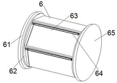
Referring to fig. 1 and 2, the present invention provides a drawing reading device for engineering management: comprises a base 1, a right bracket 2, a left bracket 3, a power cord 4, a controller 5 and a rotary reading mechanism 6, wherein the top end of the right side of the base 1 is connected with the right bracket 2, the bottom end of the left side of the rotary reading mechanism 6 is connected with the left bracket 3, the rotary reading mechanism 6 comprises a first supporting plate 61, a side plate 62, a rotary mechanism 63, an ash cleaning mechanism 64 and a second supporting plate 65, the middle part of the left side of the first supporting plate 61 is connected with the left bracket 3, the right side of the first supporting plate 61 is connected with the side plate 62, the right side of the side plate 62 is rotatably connected with the rotary mechanism 63, the top end surface of the rotary mechanism 63 is provided with the ash cleaning mechanism 64, the right side of the rotary mechanism 63 is rotatably matched with the second supporting plate 65, the top end of the left side of the base 1 is connected with the left bracket 3, the right side of the top end of the left bracket 3 is electrically connected with the power cord 4, the controller 5 is arranged at the upper end of the power cord 4, which is beneficial to the reasonable distribution of each part, the top end of the base 1 is provided with two fixing frames, the left side and the right side of the base are parallel to each other and are connected with the right support 2 and the left support 3 through round rods, the device is favorable for better stabilization, the side plates 62 are two, the size of the side plates is the same, the side plates are respectively installed on the left side and the right side of the rotating mechanism 63, the structural stability of the rotating mechanism 63 is favorable for keeping, the ash cleaning mechanism 64 is provided with six, the structure of the ash cleaning mechanism is consistent, the ash cleaning mechanism is respectively installed on the upper portion of the top end face of the rotating mechanism 63, and the dust on each panel is favorable for being conveniently cleaned.
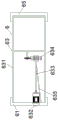
Please refer to fig. 3, the utility model provides a drawing reading device for engineering management, rotary mechanism 63 includes casing 631, motor 632, connecting axle 633, intermittent type slewing mechanism 634 and bottom plate 635, casing 631 left side is connected with curb plate 62, motor 632 has been inlayed to the inside left side of casing 631, motor 632 right side middle part and connecting axle 633 normal running fit, connecting axle 633 right side rotates with intermittent type slewing mechanism 634 to be connected, connecting axle 633 right side bottom is connected with bottom plate 635, be favorable to through rotating better show drawing, casing 631 is formed by the preparation of ya keli material, be favorable to environmental protection and better show drawing.
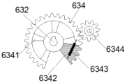
Referring to fig. 4 and 5, the utility model provides a drawing reading device for engineering management, the rotating mechanism 634 includes a driving gear 6341, an irregular gear 6342, a spring 6343, a driven gear 6344 and a connecting rod 6345, the middle portion of the left side of the driving gear 6341 is rotationally matched with the connecting shaft 633, the driving gear 6341 and the irregular gear 6342 rotate coaxially, the spring 6343 is fixedly connected to the left side of the top end of the irregular gear 6342, the middle portion of the right side of the driving gear 6341 is engaged with the driven gear 6344, the middle portion of the bottom end of the driven gear 6344 is connected with the connecting rod 6345, which is beneficial to driving the casing 631 to rotate, six connecting rods 6345 are provided, the driving gear 6341, the irregular gear 6342 and the driven gear 6344 are made of No. 5 steel, so that the driving gear 6341, the irregular gear 6342 and the driven gear 6344 are wear-resistant and the service life of the driving gear is prolonged.
This patent casing 631 form by the preparation of ya keli material, ya keli is nontoxic odorless material under the normal atmospheric temperature to have waterproof, explosion-proof, the performance of preapring for an unfavorable turn of events shape, compensatied not enough of materials such as iron stand, plastics frame, yakeli material often has longer life, existing good pleasing to the eye effect, more has easy clear characteristics.
When a user wants to use the patent, the drawing reading device for engineering management can be placed at a proper position, the power cord 4 is connected, the user can place the required drawing on six surfaces of the outer side of the casing 631, then the controller 5 is pressed, the motor shaft drives the connecting shaft 633 to rotate under the action of the motor 632, the driving gear 6341 is driven to rotate, when the irregular gear 6342 on the driving gear 6341 is meshed with the driven gear 6344, the driven gear 6344 rotates simultaneously, at the same time, the driving gear 6341 also rotates, the rotating force drives the irregular gear to rotate through the spring 6343, the irregular gear 6342 rotates to leave the driven gear 6344, the spring 6343 rebounds to the original position through the force of the spring 6343, when the driven gear 6344 is meshed with the driving gear 6341, the connecting rod 6345 at the middle part of the bottom end of the driven gear 6344 rotates along with the driving gear 6341, drive casing 631 rotation to realize rotatory drawing, the function of looking up fast, place the drawing and probably accumulate the dust after a specified time, the user can clean the drawing through deashing mechanism, keeps the drawing clear clean and tidy.
The basic principles and the main features of the invention and the advantages of the invention have been shown and described above, it will be evident to those skilled in the art that the invention is not limited to the details of the foregoing illustrative embodiments, but that the invention may be embodied in other specific forms without departing from the spirit or essential characteristics of the invention. The present embodiments are therefore to be considered in all respects as illustrative and not restrictive, the scope of the invention being indicated by the appended claims rather than by the foregoing description, and all changes which come within the meaning and range of equivalency of the claims are therefore intended to be embraced therein. Any reference sign in a claim should not be construed as limiting the claim concerned.
Furthermore, it should be understood that although the present description refers to embodiments, not every embodiment may contain only a single embodiment, and such description is for clarity only, and those skilled in the art should integrate the description, and the embodiments may be combined as appropriate to form other embodiments understood by those skilled in the art.
Claims (8)
1. A drawing reading device for engineering management comprises a base (1), a right support (2), a left support (3), a power line (4) and a controller (5), wherein the top end of the right side of the base (1) is connected with the right support (2);
the method is characterized in that: still include rotatory reading mechanism (6), rotatory reading mechanism (6) left side bottom is connected with left socle (3), rotatory reading mechanism (6) are including first backup pad (61), curb plate (62), rotary mechanism (63), deashing mechanism (64) and second backup pad (65), first backup pad (61) left side middle part is connected with left socle (3), first backup pad (61) right side is connected with curb plate (62), curb plate (62) right side is rotated with rotary mechanism (63) and is connected, rotary mechanism (63) top end face is provided with deashing mechanism (64), rotary mechanism (63) right side and second backup pad (65) normal running fit.
2. The drawing viewing device for engineering management according to claim 1, wherein: the base (1) left side top is connected with left socle (3), left socle (3) top right side is connected with power cord (4) electricity, controller (5) are installed to power cord (4) upper end.
3. The drawing viewing device for engineering management according to claim 1, wherein: rotary mechanism (63) includes casing (631), motor (632), connecting axle (633), intermittent type slewing mechanism (634) and bottom plate (635), casing (631) left side is connected with curb plate (62), motor (632) have been inlayed to casing (631) inside left side, motor (632) right side middle part and connecting axle (633) normal running fit, connecting axle (633) right side is rotated with intermittent type slewing mechanism (634) and is connected, connecting axle (633) right side bottom is connected with bottom plate (635).
4. The drawing viewing device for engineering management according to claim 3, wherein: slewing mechanism (634) includes driving gear (6341), irregular gear (6342), spring (6343), driven gear (6344) and connecting rod (6345), driving gear (6341) left side middle part and connecting axle (633) normal running fit, driving gear (6341) and irregular gear (6342) coaxial rotation, irregular gear (6342) top left side fixedly connected with spring (6343), driving gear (6341) right side middle part meshes with driven gear (6344) mutually, driven gear (6344) bottom middle part is connected with connecting rod (6345).
5. The drawing viewing device for engineering management according to claim 1, wherein: the top end of the base (1) is provided with two fixing frames which are connected with the right support (2) and the left support (3) through round rods in parallel.
6. The drawing viewing device for engineering management according to claim 1, wherein: the two side plates (62) are arranged and have the same size and are respectively arranged on the left side and the right side of the rotating mechanism (63).
7. The drawing viewing device for engineering management according to claim 1, wherein: six ash removal mechanisms (64) are arranged, have the same structure and are respectively arranged at the upper part of the top end surface of the rotating mechanism (63).
8. The drawing viewing device for engineering management according to claim 4, wherein: the six connecting rods (6345) are identical in structure and are respectively mounted at the upper ends of six faces of the shell (631).
Priority Applications (1)
| Application Number | Priority Date | Filing Date | Title |
|---|---|---|---|
| CN202021683462.5U CN215126224U (en) | 2020-08-13 | 2020-08-13 | Drawing reading device for engineering management |
Applications Claiming Priority (1)
| Application Number | Priority Date | Filing Date | Title |
|---|---|---|---|
| CN202021683462.5U CN215126224U (en) | 2020-08-13 | 2020-08-13 | Drawing reading device for engineering management |
Publications (1)
| Publication Number | Publication Date |
|---|---|
| CN215126224U true CN215126224U (en) | 2021-12-14 |
Family
ID=79349198
Family Applications (1)
| Application Number | Title | Priority Date | Filing Date |
|---|---|---|---|
| CN202021683462.5U Active CN215126224U (en) | 2020-08-13 | 2020-08-13 | Drawing reading device for engineering management |
Country Status (1)
| Country | Link |
|---|---|
| CN (1) | CN215126224U (en) |
-
2020
- 2020-08-13 CN CN202021683462.5U patent/CN215126224U/en active Active
Similar Documents
| Publication | Publication Date | Title |
|---|---|---|
| CN215126224U (en) | Drawing reading device for engineering management | |
| CN208141736U (en) | A kind of LED display with functions of waterproof and dustproof | |
| CN110728928A (en) | Display device for education information consultation | |
| CN211858034U (en) | Energy-saving outdoor advertising lamp box with solar energy auxiliary energy supply | |
| CN213488044U (en) | Handicraft display device | |
| CN211866119U (en) | Solar panel self-cleaning device | |
| CN214384712U (en) | Large outdoor billboard | |
| CN202967044U (en) | Friction roller storage device | |
| CN209822177U (en) | Large-scale billboard with screen cleaning equipment | |
| CN109109517B (en) | Intelligent white board for office | |
| CN211207912U (en) | Advertising board convenient for replacing advertising cloth | |
| CN209345239U (en) | A kind of multimedia equipment easy to remove | |
| CN209533405U (en) | A kind of intelligent robot transmission mechanism of flexibility and reliability | |
| CN202472976U (en) | Multifunctional optical dynamic media comprehensive animation demonstrating device and grating mesh piece mover thereof | |
| CN207503542U (en) | A kind of Ads on Vehicles display screen with defencive function | |
| CN210606563U (en) | Mobile advertisement robot | |
| CN216719124U (en) | Advertisement all-in-one terminal with sensitive touch | |
| CN220033509U (en) | Reed-based biodegradable film environment-friendly recovery device | |
| CN220428056U (en) | Fixed bolster of quartz rotary wafer | |
| CN216119415U (en) | Outdoor exhibitions is with removing propaganda lamp house | |
| CN217966425U (en) | Environment-friendly type dust removing equipment for polishing CuCr30 contact | |
| CN212430210U (en) | Protective type mounting base for power equipment | |
| CN217839212U (en) | Polyester hot melt silk production facility | |
| CN219550430U (en) | Lighting device convenient to clearance | |
| CN220137911U (en) | Magical color advertising lamp box |
Legal Events
| Date | Code | Title | Description |
|---|---|---|---|
| GR01 | Patent grant | ||
| GR01 | Patent grant |