CN215092822U - Machining burnishing device - Google Patents
Machining burnishing device Download PDFInfo
- Publication number
- CN215092822U CN215092822U CN202121704809.4U CN202121704809U CN215092822U CN 215092822 U CN215092822 U CN 215092822U CN 202121704809 U CN202121704809 U CN 202121704809U CN 215092822 U CN215092822 U CN 215092822U
- Authority
- CN
- China
- Prior art keywords
- fixedly connected
- polishing
- gear
- workbench
- plate
- Prior art date
- Legal status (The legal status is an assumption and is not a legal conclusion. Google has not performed a legal analysis and makes no representation as to the accuracy of the status listed.)
- Active
Links
Images


Landscapes
- Finish Polishing, Edge Sharpening, And Grinding By Specific Grinding Devices (AREA)
Abstract
The utility model discloses a machining burnishing device, comprises a workbench, the equal fixedly connected with U type positioning seat in both ends at workstation surface top, the right-hand member fixed mounting of workstation inner chamber bottom has servo motor, servo motor's output fixed mounting has first gear, there is the bull stick through bearing swing joint between the middle-end of workstation both sides, the lower extreme fixed mounting of bull stick has the second gear. The utility model discloses a under the effect of mutually supporting between workstation, U type positioning seat, servo motor, first gear, second gear, bull stick, cam, fixed plate, hydraulic stem, polishing motor, polishing dish, backup pad, first spring, sliding sleeve, slide bar, push pedal and second spring and the splint, realized that this device can circulate incessant pair part and polish processing, very big saving the required time of circulation operation, improved the efficiency of work.
Description
Technical Field
The utility model relates to a machining technical field specifically is a machining burnishing device.
Background
Mechanical polishing relies on the grinding, rolling action of very fine polishing powder to remove a very thin layer of metal from the ground surface of a sample, polishing often used to enhance the appearance of the product, prevent contamination of the instrument, remove oxidation, create a reflective surface, or prevent corrosion of the tubing, in metallurgy polishing is used to create a flat, defect free surface for microscopic examination of the microstructure of the metal, and polishing stainless steel also increases the cleanliness of stainless steel.
However, the conventional polishing device is inconvenient to fix the polished part, and wastes a large amount of time during circular operation, so that the working efficiency is extremely low, and the production requirement of machining cannot be met.
SUMMERY OF THE UTILITY MODEL
An object of the utility model is to provide a machining burnishing device possesses the advantage that work efficiency is high, has solved current burnishing device and has been not convenient for fix the part of polishing, and has wasted a large amount of time during the circulation operation, and then has leaded to the problem that work efficiency is extremely low.
In order to achieve the above object, the utility model provides a following technical scheme: a machining polishing device comprises a workbench, wherein U-shaped positioning seats are fixedly connected to two ends of the top of the outer surface of the workbench, a servo motor is fixedly mounted at the right end of the bottom of an inner cavity of the workbench, a first gear is fixedly mounted at the output end of the servo motor, a rotating rod is movably connected between the middle ends of two sides of the workbench through a bearing, a second gear is fixedly mounted at the lower end of the rotating rod, the surface of the second gear is meshed with the surface of the first gear, a cam is fixedly mounted at the middle end of the rotating rod, a fixed plate is fixedly connected to the top of the rotating rod, a hydraulic rod is fixedly mounted at the bottom of the fixed plate and in front of the rotating rod, a polishing motor is fixedly mounted at the output end of the hydraulic rod, a polishing disc is fixedly mounted at the output end of the polishing motor, and sliding rods are fixedly connected to two ends of the top of the workbench and below the U-shaped positioning seats, the utility model discloses a sliding rod, including slide bar, push rod, the equal fixedly connected with second spring in both ends, two of one side is kept away from each other to the push pedal, the top fixedly connected with push pedal of slide bar, two the equal fixedly connected with second spring in both ends of one side, two between the surface of second spring and keep away from one side fixedly connected with splint of push pedal, the bottom fixedly connected with backup pad of slide bar, the surface swing joint of cam is in the surface of backup pad, the first spring of fixedly connected with between the upper end of one side of cam and workstation inner chamber is just kept away from to the middle-end of backup pad.
Preferably, the middle ends of the two clamping plates close to one side are fixedly connected with guide rods, and the surfaces of the guide rods are movably connected to the middle end of the push plate.
Preferably, the upper ends of the two sides of the inner cavity of the workbench are fixedly connected with limiting rods below the first springs, and the surfaces of the limiting rods are movably connected to the lower ends of the supporting plates.
Preferably, a limiting groove is formed in the upper end of the front surface of the rotating rod, a limiting plate is fixedly connected to the back surface of the polishing motor, and one end, far away from the polishing motor, of the limiting plate is movably connected to the surface of the limiting groove.
Preferably, the periphery of the bottom of the outer surface of the workbench is fixedly connected with rubber supporting blocks, and the distance between every two adjacent rubber supporting blocks is equal.
Preferably, the front surface of the workbench is movably provided with a sealing door through a hinge, and the right end of the sealing door is fixedly connected with a handle.
Compared with the prior art, the beneficial effects of the utility model are as follows:
1. the utility model discloses a setting of two U type positioning seats in workstation top, be convenient for hold and fix a position two required polished parts simultaneously, it can drive first gear to rotate to carry out work through starting servo motor simultaneously, first gear rotation can drive the second gear and the bull stick rotates along the bearing on the workstation, can drive cam and fixed plate rotation when the bull stick is rotatory, the fixed plate rotation can drive the hydraulic stem, polishing motor and polishing dish rotate, until the polishing dish is in the top of left side U type positioning seat, during this period, the cam rotation can promote the left side backup pad, make the backup pad compress the first spring in left side, and when producing tension to the backup pad, can drive the left side sliding sleeve and be close to the one side that is in left side U type positioning seat along the surface of left side slide bar, the sliding sleeve removes and can drive the push pedal, The second spring moves with the clamping plate until the clamping plate is tightly attached to the surface of the part placed in the U-shaped positioning seat, so that the effect of clamping and fixing the part is achieved, the polishing motor and the polishing disc can be driven to move downwards by controlling the extension of the hydraulic rod, the polishing disc can be driven to rotate by starting the polishing motor to polish the part until the polishing disc is contacted with the surface of the part, so that the effect of quickly polishing the left part is achieved, when the polishing work of the left part is completed, the polishing motor is controlled to stop working and contract the hydraulic rod, so that the polishing motor and the polishing disc are driven to be separated from the surface of the part and return to the original position, and meanwhile, the first gear, the second gear, the rotating rod, the cam, the fixed plate, the hydraulic rod, the polishing motor and the polishing disc can be driven to rotate by controlling the servo motor to work, the polishing disc can be positioned above the U-shaped positioning seat on the right side, under the action of the rotation of the cam, the clamping plate on the right side can be pushed to clamp and fix the parts in the U-shaped positioning seat, the polishing motor and the polishing disc can be driven to move downwards by controlling the extension of the hydraulic rod again, the polishing disc can be driven to rotate by starting the polishing motor to polish the parts until the polishing disc is contacted with the surfaces of the parts, and further the effect of quickly polishing the parts on the right side is achieved, during the period, the tension of the first spring on the left side is released when the cam rotates, the supporting plate, the sliding sleeve, the pushing plate, the second spring and the clamping plate are pushed to be restored to the original positions, so that the clamping plate can be separated from the surfaces of the parts in the U-shaped positioning seat on the left side, and a user can take out and replace the polished parts conveniently, thereby reached polishing work and the effect that the work was gone on simultaneously of part change, convenient to use person is quick and the circulation is polished the operation to the part, under whole complex effect, realized that this device can circulate incessant polishing to the part and process, very big saving the required time of circulation operation, improved the efficiency of work, it is not convenient for fix the part of polishing to have solved current burnishing device, and wasted a large amount of time during the circulation operation, and then leaded to the problem that work efficiency is extremely low.
2. The utility model discloses a setting of guide bar has reached and has carried out spacing purpose between splint and the push pedal, through the setting of gag lever post, has reached and has carried out spacing purpose to the backup pad, through the setting of spacing groove and limiting plate, has reached and has carried out spacing purpose to polishing motor, through the setting of rubber support piece, has reached and has carried out the purpose that the shock attenuation was supported to the whole, through the setting of sealing door, convenient to use person maintains the inside of workstation.
Drawings
FIG. 1 is a schematic structural view of the present invention;
FIG. 2 is a schematic sectional view of the worktable of the present invention;
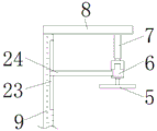
FIG. 3 is a schematic view of the left side of the rotating rod of the present invention in a partial sectional view;
fig. 4 is a schematic view of the cam of the present invention.
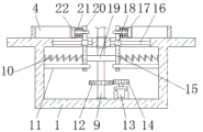
In the figure: 1. a work table; 2. a sealing door; 3. a rubber support block; 4. a U-shaped positioning seat; 5. a polishing disk; 6. polishing the motor; 7. a hydraulic lever; 8. a fixing plate; 9. a rotating rod; 10. a first spring; 11. a limiting rod; 12. a second gear; 13. a servo motor; 14. a first gear; 15. a support plate; 16. a slide bar; 17. a guide bar; 18. a sliding sleeve; 19. a cam; 20. pushing the plate; 21. a second spring; 22. a splint; 23. a limiting groove; 24. and a limiting plate.
Detailed Description
The technical solutions in the embodiments of the present invention will be described clearly and completely with reference to the accompanying drawings in the embodiments of the present invention, and it is obvious that the described embodiments are only some embodiments of the present invention, not all embodiments. Based on the embodiments in the present invention, all other embodiments obtained by a person skilled in the art without creative work belong to the protection scope of the present invention.
In the description herein, it is to be understood that the terms "center," "upper," "lower," "front," "rear," "left," "right," "vertical," "horizontal," "top," "bottom," "inner," "outer," and the like are used in the orientations and positional relationships indicated in the drawings to facilitate the description of the patent and to simplify the description, but do not indicate or imply that the referenced device or element must have a particular orientation, be constructed and operated in a particular orientation, and thus are not to be considered limiting of the patent. In the description of the present application, it should be noted that unless otherwise explicitly stated or limited, the terms "mounted," "connected," and "disposed" are to be construed broadly and can, for example, be fixedly connected, disposed, detachably connected, disposed, or integrally connected and disposed. The specific meaning of the above terms in this patent may be understood by those of ordinary skill in the art as appropriate.
Referring to fig. 1-4, a machining polishing device comprises a worktable 1, rubber supporting blocks 3 are fixedly connected to the periphery of the bottom of the outer surface of the worktable 1, the distance between two adjacent rubber supporting blocks 3 is equal, the purpose of shock absorption and support of the whole body is achieved by the arrangement of the rubber supporting blocks 3, a sealing door 2 is movably mounted on the front surface of the worktable 1 through hinges, a handle is fixedly connected to the right end of the sealing door 2, the inside of the worktable 1 is conveniently maintained by a user through the arrangement of the sealing door 2, U-shaped positioning seats 4 are fixedly connected to two ends of the top of the outer surface of the worktable 1, a servo motor 13 is fixedly mounted at the right end of the bottom of the inner cavity of the worktable 1, a first gear 14 is fixedly mounted at the output end of the servo motor 13, a rotating rod 9 is movably connected between the middle ends of two sides of the worktable 1 through a bearing, a second gear 12 is fixedly mounted at the lower end of the rotating rod 9, the surface of the second gear 12 is meshed with the surface of the first gear 14, a cam 19 is fixedly mounted at the middle end of the rotating rod 9, a fixing plate 8 is fixedly connected to the top of the rotating rod 9, a hydraulic rod 7 is fixedly mounted at the bottom of the fixing plate 8 and positioned in front of the rotating rod 9, a polishing motor 6 is fixedly mounted at the output end of the hydraulic rod 7, a limiting groove 23 is formed in the upper end of the front surface of the rotating rod 9, a limiting plate 24 is fixedly connected to the back surface of the polishing motor 6, one end, far away from the polishing motor 6, of the surface of the limiting plate 24 is movably connected to the surface of the limiting groove 23, the purpose of limiting the polishing motor 6 is achieved through the arrangement of the limiting groove 23 and the limiting plate 24, a polishing disc 5 is fixedly mounted at the output end of the polishing motor 6, a sliding rod 16 is fixedly connected to both ends of the top of the workbench 1 and positioned below the U-shaped positioning seat 4, and a sliding sleeve 18 is movably connected to the surface of the sliding rod 16, the top of the sliding sleeve 18 is fixedly connected with a push plate 20, two ends of one side of the two push plates 20, which are far away from each other, are fixedly connected with second springs 21, one side of the two second springs 21, which is far away from the push plate 20, is fixedly connected with clamping plates 22, the middle ends of the two clamping plates 22, which are close to one side, are fixedly connected with guide rods 17, the surfaces of the guide rods 17 are movably connected with the middle ends of the push plates 20, the purpose of limiting between the clamping plates 22 and the push plates 20 is achieved through the arrangement of the guide rods 17, the bottom of the sliding sleeve 18 is fixedly connected with a supporting plate 15, the surfaces of the cams 19 are movably connected with the surface of the supporting plate 15, the upper ends of two sides of the inner cavity of the workbench 1, which are positioned below the first springs 10, are fixedly connected with limiting rods 11, the surfaces of the limiting rods 11 are movably connected with the lower ends of the supporting plate 15, and the purpose of limiting of the supporting plate 15 is achieved through the arrangement of the limiting rods 11, a first spring 10 is fixedly connected between the middle end of the supporting plate 15 and the side far away from the cam 19 and the upper end of the inner cavity of the workbench 1, two U-shaped positioning seats 4 at the top of the workbench 1 are arranged to facilitate accommodating and positioning two components to be polished simultaneously, a servo motor 13 is started to work to drive a first gear 14 to rotate, the first gear 14 rotates to drive a second gear 12 and a rotating rod 9 to rotate along a bearing on the workbench 1, the rotating rod 9 rotates to drive the cam 19 and a fixing plate 8 to rotate, the fixing plate 8 rotates to drive a hydraulic rod 7, a polishing motor 6 and a polishing disc 5 to rotate until the polishing disc 5 is positioned right above the U-shaped positioning seat 4 at the left side, during the period, the cam 19 rotates to push the supporting plate 15 at the left side, so that the supporting plate 15 compresses the first spring 10 at the left side, when tension is generated on the supporting plate 15, the left sliding sleeve 18 can be driven to approach one side of the left U-shaped positioning seat 4 along the surface of the left sliding rod 16, the sliding sleeve 18 can be moved to drive the push plate 20, the second spring 21 and the clamping plate 22 to move until the clamping plate 22 is tightly attached to the surface of a part placed in the U-shaped positioning seat 4, the effect of clamping and fixing the part is further achieved, the polishing motor 6 and the polishing disc 5 can be driven to move downwards by controlling the extension of the hydraulic rod 7 until the polishing disc 5 is contacted with the surface of the part, the polishing disc 5 can be driven to rotate by starting the polishing motor 6 to polish the part, the effect of quickly polishing the left part is further achieved, after the polishing work of the left part is completed, the polishing motor 6 is controlled to stop working and contract with the hydraulic rod 7, and the polishing motor 6 and the polishing disc 5 are driven to be separated from the surface of the part and return to the original position, meanwhile, the servo motor 13 is controlled to work to drive the first gear 14, the second gear 12, the rotating rod 9, the cam 19, the fixing plate 8, the hydraulic rod 7, the polishing motor 6 and the polishing disk 5 to rotate, so that the polishing disk 5 can be positioned above the right U-shaped positioning seat 4, under the rotation action of the cam 19, the right clamping plate 22 can be pushed to clamp and fix components inside the U-shaped positioning seat 4, the hydraulic rod 7 is controlled again to extend to drive the polishing motor 6 and the polishing disk 5 to move downwards until the polishing disk 5 is contacted with the surface of the component, the polishing motor 6 is started to work to drive the polishing disk 5 to rotate to polish the component, the effect of quickly polishing the right component is achieved, and during the period, the tension of the left first spring 10 is released while the cam 19 rotates, promote backup pad 15, sliding sleeve 18, push pedal 20, second spring 21 and splint 22 resume to the normal position, and make splint 22 break away from with the surface of the inside part of left side U type positioning seat 4, and then the person of facilitating the use takes out and changes the part that has polished, thereby reached the effect that polishing work and part change work go on simultaneously, the person of facilitating the use is fast and the circulation polishes the operation to the part, under whole complex effect, realized that this device can circulate incessant pair part polishing processing, the very big required time of circulation operation that has saved, the efficiency of work has been improved, it is not convenient for to fix the part that polishes to have solved current burnishing device, and wasted a large amount of time during circulation operation, and then lead to the problem that work efficiency is low.
All the components in the utility model are universal standard components or components known by technicians in the field, the structure and principle of the components are known by technicians in the technical manual or known by conventional experimental methods, standard parts used in the application document can be purchased from the market, the components in the application document can be customized according to the description of the specification and the accompanying drawings, the specific connection mode of each component adopts conventional means such as bolts, rivets, welding and the like mature in the prior art, machines, parts and equipment adopt conventional models in the prior art, the control mode is automatically controlled by a controller, a control circuit of the controller can be realized by simple programming of technicians in the field, the components belong to the common knowledge in the field, and the application document is mainly used for protecting mechanical devices, so the control mode and circuit connection are not explained in detail in the application document, no specific description will be made herein.
When the polishing device is used, two U-shaped positioning seats 4 at the top of the workbench 1 are arranged, two parts to be polished can be conveniently accommodated and positioned at the same time, meanwhile, the servo motor 13 is started to work, so that the first gear 14 can be driven to rotate, the first gear 14 can drive the second gear 12 and the rotating rod 9 to rotate along a bearing on the workbench 1, the rotating rod 9 can drive the cam 19 and the fixed plate 8 to rotate while rotating, the fixed plate 8 can drive the hydraulic rod 7, the polishing motor 6 and the polishing disk 5 to rotate until the polishing disk 5 is positioned right above the U-shaped positioning seat 4 at the left side, during the period, the cam 19 rotates to push the support plate 15 at the left side, so that the support plate 15 compresses the first spring 10 at the left side, the support plate 15 generates tension, and meanwhile, the sliding sleeve 18 at the left side can be driven to approach to one side of the U-shaped positioning seat 4 at the left side along the surface of the sliding rod 16 at the left side, the sliding sleeve 18 moves to drive the push plate 20, the second spring 21 and the clamping plate 22 move, until the clamping plate 22 is tightly attached to the surface of the part placed inside the U-shaped positioning seat 4, the effect of clamping and fixing the part is achieved, the polishing motor 6 and the polishing disc 5 can be driven to move downwards by controlling the extension of the hydraulic rod 7 until the polishing disc 5 is contacted with the surface of the part, the polishing disc 5 can be driven to rotate by starting the polishing motor 6 to work so as to polish the part, the effect of quickly polishing the left part is achieved, after the polishing work of the left part is completed, the polishing motor 6 is controlled to stop working and the hydraulic rod 7 is controlled to contract so as to drive the polishing motor 6 and the polishing disc 5 to be separated from the surface of the part and return to the original position, and meanwhile, the first gear 14 can be driven by controlling the work of the servo motor 13, The second gear 12, the rotating rod 9, the cam 19, the fixing plate 8, the hydraulic rod 7, the polishing motor 6 and the polishing disk 5 rotate, so that the polishing disk 5 can be positioned above the right U-shaped positioning seat 4, the right clamping plate 22 can be pushed to clamp and fix the parts in the U-shaped positioning seat 4 under the rotation action of the cam 19, the polishing motor 6 and the polishing disk 5 can be driven to move downwards by controlling the extension of the hydraulic rod 7 again until the polishing disk 5 is contacted with the surfaces of the parts, the polishing disk 5 can be driven to rotate to polish the parts by starting the polishing motor 6 to work, the effect of quickly polishing the right parts is achieved, in the period, the tension of the left first spring 10 is released while the cam 19 rotates, the supporting plate 15, the sliding sleeve 18, the push plate 20, the second spring 21 and the clamping plate 22 are pushed to return to the original positions, and make splint 22 break away from with the surface of the 4 internal parts of left side U type positioning seat, and then convenient to use person takes out and changes the part that has polished, thereby reached polishing work and the effect that the part change work goes on simultaneously, convenient to use person is quick and the circulation is to the part operation of polishing, under whole complex effect, realized that this device can circulate incessant polishing to the part and processed, very big saving the required time of circulation operation, improved the efficiency of work.
Although embodiments of the present invention have been shown and described, it will be appreciated by those skilled in the art that changes, modifications, substitutions and alterations can be made in these embodiments without departing from the principles and spirit of the invention, the scope of which is defined in the appended claims and their equivalents.
Claims (6)
1. The utility model provides a machining burnishing device, includes workstation (1), its characterized in that: the polishing machine is characterized in that U-shaped positioning seats (4) are fixedly connected to two ends of the top of the outer surface of the workbench (1), a servo motor (13) is fixedly mounted at the right end of the bottom of an inner cavity of the workbench (1), a first gear (14) is fixedly mounted at the output end of the servo motor (13), a rotating rod (9) is movably connected between the middle ends of two sides of the workbench (1) through a bearing, a second gear (12) is fixedly mounted at the lower end of the rotating rod (9), the surface of the second gear (12) is meshed with the surface of the first gear (14), a cam (19) is fixedly mounted at the middle end of the rotating rod (9), a fixing plate (8) is fixedly connected to the top of the rotating rod (9), a hydraulic rod (7) is fixedly mounted at the bottom of the fixing plate (8) and in front of the rotating rod (9), and a polishing motor (6) is fixedly mounted at the output end of the hydraulic rod (7), a polishing disk (5) is fixedly arranged at the output end of the polishing motor (6), slide bars (16) are fixedly connected at the two ends of the top of the workbench (1) and below the U-shaped positioning seat (4), a sliding sleeve (18) is movably connected to the surface of the sliding rod (16), a push plate (20) is fixedly connected to the top of the sliding sleeve (18), second springs (21) are fixedly connected to two ends of one side, which is far away from each other, of the two push plates (20), a clamping plate (22) is fixedly connected to one side, which is far away from the push plate (20), between the surfaces of the two second springs (21), the bottom of the sliding sleeve (18) is fixedly connected with a supporting plate (15), the surface of the cam (19) is movably connected with the surface of the supporting plate (15), a first spring (10) is fixedly connected between one side of the middle end of the supporting plate (15), which is far away from the cam (19), and the upper end of the inner cavity of the workbench (1).
2. A machining polishing device according to claim 1, characterized in that: two splint (22) are close to the middle-end fixedly connected with guide bar (17) of one side each other, the surface swing joint of guide bar (17) is in the middle-end of push pedal (20).
3. A machining polishing device according to claim 1, characterized in that: the upper end of workstation (1) inner chamber both sides just are located equal fixedly connected with gag lever post (11) in the below of first spring (10), the surperficial swing joint of gag lever post (11) is in the lower extreme of backup pad (15).
4. A machining polishing device according to claim 1, characterized in that: spacing groove (23) have been seted up to the upper end on bull stick (9) obverse surface, the back fixedly connected with limiting plate (24) of polishing motor (6), the surface of limiting plate (24) and keep away from the one end swing joint in the surface of spacing groove (23) of polishing motor (6).
5. A machining polishing device according to claim 1, characterized in that: all fixedly connected with rubber supporting blocks (3) around workstation (1) surface bottom, and the distance between two adjacent rubber supporting blocks (3) equals.
6. A machining polishing device according to claim 1, characterized in that: the front surface of the workbench (1) is movably provided with a sealing door (2) through a hinge, and the right end of the sealing door (2) is fixedly connected with a handle.
Priority Applications (1)
| Application Number | Priority Date | Filing Date | Title |
|---|---|---|---|
| CN202121704809.4U CN215092822U (en) | 2021-07-26 | 2021-07-26 | Machining burnishing device |
Applications Claiming Priority (1)
| Application Number | Priority Date | Filing Date | Title |
|---|---|---|---|
| CN202121704809.4U CN215092822U (en) | 2021-07-26 | 2021-07-26 | Machining burnishing device |
Publications (1)
| Publication Number | Publication Date |
|---|---|
| CN215092822U true CN215092822U (en) | 2021-12-10 |
Family
ID=79318911
Family Applications (1)
| Application Number | Title | Priority Date | Filing Date |
|---|---|---|---|
| CN202121704809.4U Active CN215092822U (en) | 2021-07-26 | 2021-07-26 | Machining burnishing device |
Country Status (1)
| Country | Link |
|---|---|
| CN (1) | CN215092822U (en) |
Cited By (1)
| Publication number | Priority date | Publication date | Assignee | Title |
|---|---|---|---|---|
| CN114425725A (en) * | 2021-12-27 | 2022-05-03 | 江苏博凡科精密五金科技有限公司 | Fastener for door and window and processing device thereof |
-
2021
- 2021-07-26 CN CN202121704809.4U patent/CN215092822U/en active Active
Cited By (1)
| Publication number | Priority date | Publication date | Assignee | Title |
|---|---|---|---|---|
| CN114425725A (en) * | 2021-12-27 | 2022-05-03 | 江苏博凡科精密五金科技有限公司 | Fastener for door and window and processing device thereof |
Similar Documents
| Publication | Publication Date | Title |
|---|---|---|
| CN215092822U (en) | Machining burnishing device | |
| CN219562476U (en) | Burr removing device | |
| CN219542584U (en) | Metal hardware surface treatment device | |
| CN109158997B (en) | Grinding equipment for surface of pig iron casting | |
| CN216608110U (en) | Grinding and cutting device for die steel processing | |
| CN216576994U (en) | Flat grinder convenient to it is clean | |
| CN213351910U (en) | Semi-automatic frock of polishing | |
| CN214519463U (en) | Intelligent polishing automatic device | |
| CN211136710U (en) | Automatic burnishing device of dish generates heat | |
| CN112171427A (en) | Be used for lens edge machining and forming equipment | |
| CN220446131U (en) | Diamond composite valve seat machining device | |
| CN217966229U (en) | Tool structure for metal plate machining | |
| CN218696838U (en) | Cnc engraving and milling machine is used in production of cell-phone protection film | |
| CN219212563U (en) | Precise grinding machine for machining automobile parts | |
| CN215748505U (en) | Polishing device for titanium alloy plates | |
| CN219882061U (en) | Burr removing device for cast part | |
| CN214869190U (en) | Polishing equipment for small conical surface | |
| CN114310604B (en) | Commercial pipe inner wall equipment of polishing | |
| CN220660238U (en) | Convenient operation's unhairing limit device | |
| CN215617309U (en) | Part polishing device for mechanical production | |
| CN216463568U (en) | Surface burr polishing structure for automobile parts | |
| CN212892568U (en) | Workpiece rapid taking jig | |
| CN220073472U (en) | Grinding machine for gear machining | |
| CN215788098U (en) | Camshaft blank grinding device | |
| CN219541892U (en) | Saw blade sharpening equipment for metal cutter machining |
Legal Events
| Date | Code | Title | Description |
|---|---|---|---|
| GR01 | Patent grant | ||
| GR01 | Patent grant |