CN215089489U - Closed circulation system for flushing hydraulic drive main pipeline - Google Patents
Closed circulation system for flushing hydraulic drive main pipeline Download PDFInfo
- Publication number
- CN215089489U CN215089489U CN202121401604.9U CN202121401604U CN215089489U CN 215089489 U CN215089489 U CN 215089489U CN 202121401604 U CN202121401604 U CN 202121401604U CN 215089489 U CN215089489 U CN 215089489U
- Authority
- CN
- China
- Prior art keywords
- hydraulic drive
- main line
- flushing
- pipeline
- drive main
- Prior art date
- Legal status (The legal status is an assumption and is not a legal conclusion. Google has not performed a legal analysis and makes no representation as to the accuracy of the status listed.)
- Active
Links
Images


Abstract
The utility model discloses a wash closed circulation system of hydraulic drive main line, including hydraulic drive main line and filter assembly, the oil-out of hydraulic drive main line is connected with the filter assembly through washing the main line, the oil inlet of hydraulic drive main line is connected to the other end of filter assembly, and closed circulation structure is constituteed to hydraulic drive main line and filter assembly, the quantity of hydraulic drive main line is one or more. Can adjust power rotational speed and closed pump discharge capacity output according to the pipeline condition, more accurate control flushing flow to reach the optimal washing effect, and be convenient for periodic cleaning, improved economic nature and practicality, the utility model relates to a hydraulic pressure main line system is washed in closed oil circulation can ensure flushing flow and system cleanliness, can solve unable accurate control output flow, the poor problem of extravagant energy and economic nature, and can realize that the periodicity washes convenient and fast, does not basically have the leakage phenomenon.
Description
Technical Field
The utility model relates to a hydraulic line washes the field, especially relates to a wash closed circulation system of hydraulic drive main line.
Background
Because the precision of the elements of the hydraulic system is high, the system pollution is easy to cause high failure rate, and if particles with larger hardness are mixed in the system, the service life of the elements can be shortened rapidly, and unnecessary economic loss is caused, so that the cleaning of the pipeline is a necessary link. The pipeline cleaning can remove welding slag on the inner wall of the steel pipe, particles in the manufacturing process of elements, and impurities in the machining process of joints and hoses, so that the cleanliness of hydraulic oil of a hydraulic system in normal operation is achieved.
The general hydraulic pipeline is cleaned by acid cleaning and then directly used and returned to the system, a few special equipment can adopt a circulating cleaning system, the hydraulic circulating cleaning requires that the flow state of the cleaning liquid reaches turbulent flow, the size of the turbulent flow determines the cleaning effect, the traditional cleaning method adopts an external pump station to clean, a main hydraulic pipeline is connected to the external pump station in a short way, other hydraulic elements are disconnected to form a system of a pump station, a pipeline and the pump station, the volume of the pump station is required to be overlarge, the flow of the pump station is overlarge, a large-displacement fixed displacement pump is usually adopted by a pump in the pump station, the output flow cannot be accurately controlled, a throttle valve and an overflow valve are usually used when the flow is required to be controlled, the energy is wasted, the value of the pump station is high, the purchase and manufacturing period also needs to be considered, the economical efficiency is poor, in addition, when the hydraulic system needs secondary cleaning or periodic cleaning after running for a period of time, the system has serious oil leakage and large cleaning difficulty, so that the operation becomes difficult and the operation is wrong.
SUMMERY OF THE UTILITY MODEL
The utility model aims at providing a wash closed circulation system of hydraulic drive main line solves unable accurate control output flow, can not ensure to wash flow and system cleanliness, and extravagant energy and economic nature are poor, and the operation difficulty is washed to the periodicity, the serious problem of system oil leak.
In order to solve the technical problem, the utility model adopts the following technical scheme:
the utility model relates to a wash closed circulation system of hydraulic drive main line, including hydraulic drive main line and filter assembly, the oil-out of hydraulic drive main line is connected with the filter assembly through washing the main line, the oil inlet of hydraulic drive main line is connected to the other end of filter assembly, and closed circulation structure is constituteed to hydraulic drive main line and filter assembly, the quantity of hydraulic drive main line is one or a plurality of.
Further, the filter assembly includes and is responsible for, connects, flange, ball valve, filter, the both ends of filter are connected with the ball valve and constitute the filter unit, the both ends of filter unit are connected with two parallel arrangement's the inside of being responsible for, and two are responsible for one end and are blind hole, and the other end passes through the flange seal, and two outsides of being responsible for are provided with a plurality of joints, and one side connects as the oil inlet, and the other side connects as the oil-out, the quantity of filter unit is a plurality ofly.
Furthermore, it is a plurality of the joint is equidistant arranges, just the specification of joint sets up to multiple, and the joint of different specifications is applicable to the connecting pipe intercommunication of different pipe diameters.
Furthermore, two quick connectors are arranged at two ends of the flushing main pipeline, one of the quick connectors is communicated with an oil outlet of the hydraulic driving main pipeline, and an oil inlet of the other quick connector, which is connected with the filter assembly, is communicated; and a back pressure one-way valve is arranged on an oil outlet pipeline of the filter assembly and is communicated with an oil inlet of the hydraulic drive main pipeline through a quick connector.
Further, the two main pipes are respectively connected with a pressure detection device, and the pressure detection device is a first shock-proof pressure gauge or a pressure sensor with the range of 0-60 bar; and an oil inlet pipeline of the hydraulic drive main pipeline is connected with a pressure detection device, and the pressure detection device adopts a second shock-proof pressure gauge or a pressure sensor with the range of 0-600 bar.
Furthermore, the pipe diameter and the length of the flushing main pipeline correspond to those of the connected hydraulic driving main pipeline.
Furthermore, the using number of the filtering units is controlled by opening and closing the ball valves, and the opening number of the filtering units is adjusted according to the hydraulic drive main pipeline to be cleaned.
Furthermore, the hydraulic drive main pipeline adopts a closed pump, the closed pump is an electric proportional control variable pump, and an oil suction port and a leakage port of the hydraulic drive main pipeline are connected with an oil tank.
Compared with the prior art, the utility model discloses a beneficial technological effect:
the utility model relates to a wash closed circulation system of hydraulic drive main line, including hydraulic drive main line part and filter assembly part, constitute the closed rinse-system of main line-filter-main line through the hydraulic drive main line that has the closed pump with the filter assembly, utilize the closed pump system of former equipment, do not need external pump station, wash more conveniently, the operation degree of difficulty is little, is convenient for construct, and economic nature is high; different hydraulic pressure pipelines adopt different flushing flow, can adjust power rotational speed and closed pump discharge capacity output according to the pipeline condition, select suitable person in charge size, more accurate control flushing flow to reach the optimal washing effect, and be convenient for periodic cleaning, improved economic nature and practicality, the utility model discloses a closed oil circulation flushing hydraulic pressure main line system can ensure flushing flow and system cleanliness, can solve unable accurate control output flow, the poor problem of extravagant energy and economic nature to can realize that the periodicity washes convenient and fast, no leakage phenomenon basically.
Drawings
The present invention will be further explained with reference to the following description of the drawings.
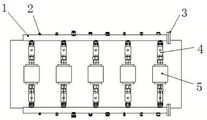
FIG. 1 is a top view of the filter assembly of the present invention;
FIG. 2 is a schematic view of the filter assembly of the present invention;
FIG. 3 is a schematic view of a closed circulation system of the flushing hydraulic drive main pipeline of the present invention;
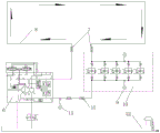
FIG. 4 is a diagram of an embodiment of a closed circulation system for flushing a hydraulically driven main pipeline according to the present invention;
description of reference numerals: 1. a main pipe; 2. a joint; 3. a flange; 4. a ball valve; 5. a filter; 6. a hydraulic drive main pipeline; 7. a quick coupling; 8. flushing the main pipeline; 9. a first shock-resistant pressure gauge; 10. a filter assembly; 11. a back pressure check valve; 12. a hydraulic oil tank; 13. a second shock-proof pressure gauge.
Detailed Description
As shown in fig. 1 to 4, a closed circulation system for flushing a hydraulic drive main pipeline includes a hydraulic drive main pipeline 6 and a filter assembly 10, an oil outlet of the hydraulic drive main pipeline 6 is connected with the filter assembly 10 through a flushing main pipeline 8, the other end of the filter assembly 10 is connected with an oil inlet of the hydraulic drive main pipeline 6, the hydraulic drive main pipeline 6 and the filter assembly 10 form a closed circulation structure, and the number of the hydraulic drive main pipelines 6 is one or more. The original hydraulic drive equipment closed system is utilized, an external pump station is not needed, and the flushing is more convenient.
The filter assembly 10 is including being responsible for 1, joint 2, flange 3, ball valve 4, filter 5, the both ends of filter 5 are connected with ball valve 4 and constitute the filter unit, and the both ends of filter unit are connected with two parallel arrangement's the 1 insides of being responsible for, and two are responsible for 1 one end and are the blind hole, and the other end passes through flange 3 and seals, and two outsides of being responsible for 1 are provided with a plurality of joints 2, and one side connects 2 as the oil inlet, and the opposite side connects 2 as the oil-out, the quantity of filter unit is a plurality of. In the design process of the hydraulic driving device, the hydraulic filtering assembly 10 is directly arranged inside the power cabin, and after the filter 5 is cleaned by the hydraulic system each time, the used filter 5 is replaced by a new filter element, so that the system can be cleaned next time.
The two ends of the flushing main pipeline 8 are connected through a quick connector 7, one end of the flushing main pipeline is connected with an oil outlet of the hydraulic driving main pipeline 6, the other end of the flushing main pipeline is connected with an oil inlet of a filter assembly 10, an oil outlet pipeline of the filter assembly 10 is provided with a backpressure one-way valve 11 and is connected with an oil inlet of the hydraulic driving main pipeline 6 through the quick connector, and the hydraulic driving main pipeline 6 and the filter assembly 10 form a closed circulation structure. The oil suction port and the leakage port of the hydraulic drive main pipeline 6 are connected with an oil tank 12, the backpressure one-way valve 11 is used for pressurizing the flushing system, the cleaning capacity of the flushing system can be improved by pressurization, the cleaning efficiency is improved, and the cleanliness of the flushing system is ensured.
2 main pipes 1 of the filter assembly 10 are respectively connected with a pressure detection device, a first shock-proof pressure gauge 9 or a pressure sensor with the range of 0-60bar is selected, an oil inlet pipeline of the hydraulic drive main pipeline 6 is connected with the pressure detection device, and a second shock-proof pressure gauge 13 or a pressure sensor with the range of 0-600bar is selected. Two pressure measurement of filter assembly 10's oil inlet and oil-out, a pressure for detecting rinse-system, through the pressure differential of the front end of comparison filter unit and rear end, more directly perceivedly confirm whether filter unit's flow is suitable, thereby whether the decision increases filter unit and adapts to rinse-system's flow, the direction of rotation of closed pump is detected when the pressure measurement on the oil inlet pipeline of hydraulic drive main line 6 is used for the start to the pump of hydraulic drive, if closed pump's direction of rotation is not to leading to through the oil inlet oil-out, then 13 sharp increases of second shock-resistant manometer pressure, need to make another coil of closed pump control solenoid valve electrified this moment, thereby it puts normally to change the closed pump, make the system normally carry out flushing work.
The diameter and length of the flushing main pipeline 8 correspond to those of the connected hydraulic driving main pipeline 6. The pipe diameter size and length, the flow rate and the viscosity of hydraulic oil are important conditions influencing the flushing effect, and different hydraulic drive main pipelines 6 adopt different flow rates and different flushing main pipelines 8.
The number of filtering units used is controlled by the opening and closing of said ball valves 4, the number of filtering units opened being adjusted according to the hydraulic drive main line 6 to be cleaned.
The hydraulic drive main pipeline 6 adopts a closed pump, the closed pump is an electric proportional control variable pump, and an oil suction port and a leakage port of the hydraulic drive main pipeline 6 are connected with an oil tank 12. The drive main line 6 of different pipe diameters adopts different flow, and the accessible is adjusted control current and is controlled the discharge capacity of closed pump, and then reaches the purpose of accurate control pipeline velocity of flow to reach the optimum washing effect, the hydraulic oil in closed circuit is exactly the oil in the closed conduit, but hydraulic drive device inevitable has some oil of few to reveal, sets up the very little oil tank of a capacity, the outflow of revealing oil and the compensation of leaking oil.
As in the embodiment of fig. 4, four hydraulically actuated main lines 6 and one filter assembly 10, the oil outlets and the oil inlets of the four hydraulic driving main pipelines 6 are respectively connected with a quick joint, the quick joints of the oil outlets are sequentially connected with a quick joint 7 of a washing main pipeline 8 through pipelines, the other end of the washing main pipeline 8 is connected with 3 joints 2 of a filter assembly 10 through quick joints, the rest filtering units are closed through a ball valve, a back pressure one-way valve 11 is arranged on a pipeline connected with an oil outlet joint 2 at the other side of the filter assembly 10, through the quick-operation joint pipe on the installation pressure measurement device, the other end is connected with the quick-operation joint of the oil inlet of hydraulic drive main line 6, 4 hydraulic drive main line 6 and filter assembly 10 constitute closed circulation structure through quick-operation joint 7 and main line 8, and the oil absorption mouth and the leakage opening of 4 hydraulic drive main line 6 are connected with oil tank 12.
The action process of the utility model is as follows:
firstly, after a quick plug 7 of a main pipeline 6 needing to be hydraulically driven in the system is detached from other elements, hydraulic elements of the system are isolated and installed on a filtering system, and partial pipelines are connected end to end, so that a flushing structure can be realized. The back pressure check valve 11 is a tubular back pressure check valve, is convenient to disassemble and assemble, and can be replaced by various back pressure check valves according to different system flow and back pressures. According to the quantity and the size of the main hydraulic drive pipeline 6, the flushing standard is checked, the flushing flow rate is determined, the flushing flow rate is calculated through the flushing flow rate and the pipeline inner diameter, the pressure value of the backpressure one-way valve 6 can be determined through the flushing flow rate, the flow model selection of the filter assembly 10 can be determined through the flushing flow rate, a plurality of filter units are selected, the control current value of the closed pump of the main hydraulic drive pipeline 6 when the rotating speed of an engine or a motor is determined, and the hydraulic oil tank 12 is the oil tank of the hydraulic system of the equipment. After each control element is determined, the closed pump is started, hydraulic oil of the system starts to flow circularly to drive impurities in the pipeline to remain on the filter element in the filter, and after the system stops running, the filter element is replaced, the filter assembly 10 and the connecting elements thereof are disassembled, and the hydraulic drive main pipeline 6 is flushed.
The filter assembly 10 is installed in the power bin, and the closed pump control current, the filter 5 selection opening quantity and the matched mark of the pipe diameter of the flushing pipeline can be attached to the filter assembly 10, so that the operation of field personnel is more convenient, and the construction is convenient.
The above-mentioned embodiments are only intended to describe the preferred embodiments of the present invention, but not to limit the scope of the present invention, and those skilled in the art should also be able to make various modifications and improvements to the technical solution of the present invention without departing from the spirit of the present invention, and all such modifications and improvements are intended to fall within the scope of the present invention as defined in the appended claims.
Claims (8)
1. The utility model provides a wash closed circulation system of hydraulic drive main line which characterized in that: the oil outlet of the hydraulic drive main pipeline (6) is connected with the filter assembly (10) through a flushing main pipeline (8), the other end of the filter assembly (10) is connected with the oil inlet of the hydraulic drive main pipeline (6), the hydraulic drive main pipeline (6) and the filter assembly (10) form a closed circulation structure, and the number of the hydraulic drive main pipeline (6) is one or more.
2. The closed circulation system for flushing a hydraulically driven main line according to claim 1, characterized in that: the filter assembly (10) comprises a main pipe (1), joints (2), flanges (3), ball valves (4) and filters (5), wherein the two ends of each filter (5) are connected with the ball valves (4) to form a filter unit, the two ends of each filter unit are connected with the inner sides of the main pipes (1) arranged in parallel, one ends of the two main pipes (1) are blind holes, the other ends of the two main pipes (1) are sealed through the flanges (3), the outer sides of the two main pipes (1) are provided with the joints (2), the joints (2) on one side serve as oil inlets, the joints (2) on the other side serve as oil outlets, and the number of the filter units is multiple.
3. The closed circulation system for flushing a hydraulically driven main line according to claim 2, characterized in that: a plurality of connect (2) equidistant arranging, just the specification of connecting (2) sets up to multiple, and the joint (2) of different specifications is applicable to the connecting pipe intercommunication of different pipe diameters.
4. The closed circulation system for flushing a hydraulically driven main line according to claim 1, characterized in that: two quick connectors (7) are arranged at two ends of the flushing main pipeline (8), one quick connector (7) is communicated with an oil outlet of the hydraulic driving main pipeline (6), and an oil inlet of the other quick connector (7) connected with a filter assembly (10) is communicated; the oil outlet pipeline of the filter assembly (10) is provided with a back pressure one-way valve (11), and the back pressure one-way valve (11) is communicated with an oil inlet of the hydraulic drive main pipeline (6) through a quick connector (7).
5. The closed circulation system for flushing a hydraulically driven main line according to claim 1, characterized in that: the two main pipes (1) are respectively connected with a pressure detection device, and the pressure detection device is a first shock-proof pressure gauge (9) or a pressure sensor with the measuring range of 0-60 bar; and an oil inlet pipeline of the hydraulic drive main pipeline (6) is connected with a pressure detection device, and the pressure detection device adopts a second shock-proof pressure gauge (13) or a pressure sensor with the measuring range of 0-600 bar.
6. The closed circulation system for flushing a hydraulically driven main line according to claim 1, characterized in that: the diameter and the length of the flushing main pipeline (8) correspond to those of the connected hydraulic driving main pipeline (6).
7. The closed circulation system for flushing a hydraulically driven main line according to claim 2, characterized in that: the number of filtering units used is controlled by opening and closing the ball valves (4), and the number of filtering units to be opened is adjusted according to the main hydraulic drive pipeline (6) to be cleaned.
8. The closed circulation system for flushing a hydraulically driven main line according to claim 1, characterized in that: the hydraulic drive main pipeline (6) adopts a closed pump, the closed pump is an electric proportional control variable pump, and an oil suction port and a leakage port of the hydraulic drive main pipeline (6) are connected with an oil tank (12).
Priority Applications (1)
| Application Number | Priority Date | Filing Date | Title |
|---|---|---|---|
| CN202121401604.9U CN215089489U (en) | 2021-06-23 | 2021-06-23 | Closed circulation system for flushing hydraulic drive main pipeline |
Applications Claiming Priority (1)
| Application Number | Priority Date | Filing Date | Title |
|---|---|---|---|
| CN202121401604.9U CN215089489U (en) | 2021-06-23 | 2021-06-23 | Closed circulation system for flushing hydraulic drive main pipeline |
Publications (1)
| Publication Number | Publication Date |
|---|---|
| CN215089489U true CN215089489U (en) | 2021-12-10 |
Family
ID=79310156
Family Applications (1)
| Application Number | Title | Priority Date | Filing Date |
|---|---|---|---|
| CN202121401604.9U Active CN215089489U (en) | 2021-06-23 | 2021-06-23 | Closed circulation system for flushing hydraulic drive main pipeline |
Country Status (1)
| Country | Link |
|---|---|
| CN (1) | CN215089489U (en) |
-
2021
- 2021-06-23 CN CN202121401604.9U patent/CN215089489U/en active Active
Similar Documents
| Publication | Publication Date | Title |
|---|---|---|
| CN101543825B (en) | Closed self-circulation hydraulic pipeline flusher | |
| CN104107816B (en) | A kind of fluid pressure line cleans pumping plant | |
| CN202876653U (en) | Ceramic film filter device | |
| CN201431986Y (en) | Flushing device for closed self-circulating hydraulic pipeline | |
| CN113245317A (en) | Closed circulation system for flushing hydraulic drive main pipeline | |
| CN206221429U (en) | A kind of oil filtering device that function is detected with online dustiness | |
| CN215089489U (en) | Closed circulation system for flushing hydraulic drive main pipeline | |
| CN113323945A (en) | High cleanliness hydraulic pipeline cleaning system | |
| CN210434315U (en) | Reusable tubular membrane detection device | |
| CN106906887B (en) | Vacuum sewage discharging device | |
| CN201866018U (en) | Oil filtering device for industrial hydraulic and lubricating system | |
| CN202418521U (en) | Automatic gearbox cleaning and oil-changing device and cleaning and oil-changing component | |
| CN214865710U (en) | Quick cleaning module | |
| CN101949403A (en) | Oil filter for industrial hydraulic and lubrication system | |
| CN107449709A (en) | A kind of filter check device | |
| CN205937085U (en) | Mechanical seal of booster pump washes pipeline | |
| CN210251888U (en) | Quick leak hunting device of tubular membrane module | |
| CN214344875U (en) | Hydraulic engineering is with preventing stifled pipeline | |
| CN213066682U (en) | Resistance on-line monitoring system for seawater direct cooling circulating water system | |
| CN212202374U (en) | Bypass cleaning structure of metering pump | |
| CN101732911A (en) | FX backwashing filter | |
| CN201760159U (en) | Backwash filter | |
| CN219664643U (en) | Catheter inner cavity cleaning system with pulse pressure | |
| CN213887458U (en) | Pipeline hydraulic device | |
| CN213885177U (en) | Filtering device |
Legal Events
| Date | Code | Title | Description |
|---|---|---|---|
| GR01 | Patent grant | ||
| GR01 | Patent grant |