CN215077929U - Multifunctional wet tissue machine - Google Patents
Multifunctional wet tissue machine Download PDFInfo
- Publication number
- CN215077929U CN215077929U CN202121163179.4U CN202121163179U CN215077929U CN 215077929 U CN215077929 U CN 215077929U CN 202121163179 U CN202121163179 U CN 202121163179U CN 215077929 U CN215077929 U CN 215077929U
- Authority
- CN
- China
- Prior art keywords
- towel
- cloth
- piece
- bottle
- machine
- Prior art date
- Legal status (The legal status is an assumption and is not a legal conclusion. Google has not performed a legal analysis and makes no representation as to the accuracy of the status listed.)
- Active
Links
Images

Abstract
The utility model belongs to daily small household electrical appliances field, concretely relates to multi-functional wet piece of cloth machine of wetting, including casing and frame, the casing covers the frame and forms the inner chamber, and casing one end is equipped with out the piece of cloth mouth, and the intracavity is equipped with conveying mechanism, sprays mechanism and roll up piece of cloth mechanism, rolls up piece of cloth mechanism and is connected with conveying mechanism, sprays the mechanism and is connected with conveying mechanism, its characterized in that, sprays the mechanism and includes a plurality of solution bottles, corresponds quantity electric pump, valve body and shower, and the solution bottle all is connected to the valve body through corresponding the electric pump, is connected to the shower via the valve body, and the shower sprays the direction towards conveying mechanism. The utility model discloses the function is various, according to the different settings of solution bottle, can reach output dry piece of cloth, wet piece of cloth, makeup removing water piece of cloth, alcohol disinfection piece of cloth etc. is applicable to more sight, especially is fit for women's family and uses.
Description
Technical Field
The utility model belongs to the field of daily small household appliances, in particular to a multifunctional wet tissue machine.
Background
With the development of social economy and the improvement of the living standard of people, the wet tissue becomes one of important living goods in the life of people, the consumption is more and more large, and the use of the wet tissue machine is more and more extensive. The prior art wet tissue machine for producing wet tissue comprises the steps of stretching a coiled non-woven fabric arranged in the machine out of a coil, cutting the non-woven fabric into sections according to a certain length by a cutter, spraying water for wetting, coiling the non-woven fabric on a towel coiling cylinder, and then outputting. But the wet tissue machine in the prior art can only realize the manufacture of dry and wet tissues,
SUMMERY OF THE UTILITY MODEL
In order to solve the problems, the utility model provides a multifunctional wet towel machine which has various functions, can output dry towels, wet towels, makeup removing water towels, alcohol disinfection towels and the like according to different settings of solution bottles, is suitable for more scenes, and is particularly suitable for female families; still be equipped with adsorption apparatus and construct, adsorb the book piece of cloth in carrying, make its laminating conveyer belt, avoid producing in transportation process and play a roll, the condition of fold, adsorb the air current simultaneously and also can make the more even dispersion of liquid that sprays on rolling up the piece of cloth.
The utility model provides a scheme as follows:
a multifunctional wet tissue machine comprises a machine shell and a machine frame, wherein the machine shell covers the machine frame to form an inner cavity, the machine frame is a fixed mounting frame of each part and is usually fixed with a side surface and a ground machine shell, and other machine shells are set to be detachable shells, so that a rolled tissue and the like are convenient to maintain and replace. The intracavity is equipped with conveying mechanism, sprays the mechanism and rolls up piece of cloth mechanism, roll up piece of cloth mechanism and conveying mechanism and be connected, spray the mechanism and be connected with conveying mechanism, it is the same with prior art, roll up piece of cloth mechanism and be used for placing a roll piece of cloth and provide the output of rolling up the piece of cloth, the piece of cloth of the book of output is carried to the play piece of cloth department of casing by conveying mechanism, the person of sharing takes, the effect that sprays the mechanism is that the piece of cloth that rolls up that conveying mechanism carried is moist, form wet piece of cloth, roll up the piece of cloth and generally adopt the non-woven fabrics, high durability and convenient use, can not split or breakage after spraying moist.
Can only make the problem of the wet piece of cloth of single form to prior art wet piece of cloth machine, spray mechanism include a plurality of solution bottles, correspond the electric pump, valve body and the shower of quantity, the solution bottle all is connected to the valve body through corresponding the electric pump, is connected to the shower via the valve body, shower spray direction is towards conveying mechanism. Different solutions are used for placing different solutions, and the different solutions are sprayed on the rolled towel through the spray pipe, so that the rolled towel with different functions can be manufactured. The solution in the solution bottle is pumped by the corresponding electric pump and is communicated to the spraying pipe through the valve body for spraying, and the spraying direction faces the conveying mechanism. A funnel-shaped liquid outlet is usually arranged at the bottom of the solution bottle to prevent the solution in the bottle from remaining; the top of the solution bottle is provided with a solution replenishing port for replenishing corresponding solution.
The two solution bottles are respectively a clean water bottle and a makeup removing water bottle, the valve body adopts a three-way valve, the clean water bottle and the makeup removing water bottle are respectively connected to the inlet of the three-way valve through an electric pump, the outlet of the three-way valve is connected with a spray pipe, and when the electric pump connected with the clean water bottle is started, the spray pipe sprays clean water to manufacture common wet tissues; when the electric pump connected with the makeup removing water bottle works, the spraying pipe sprays makeup removing water to manufacture the makeup removing wet tissue.
The other scheme is that three solution bottles are respectively a clean water bottle, a makeup removing water bottle and an alcohol bottle, the valve body adopts a four-way valve, the clean water bottle, the makeup removing water bottle and the alcohol bottle are respectively connected to the inlet of the four-way valve through an electric pump, the outlet of the four-way valve is connected with a spray pipe, and when the electric pump connected with the clean water bottle is started, the spray pipe sprays clean water to manufacture the common wet tissue; when the electric pump connected with the makeup removing water bottle works, the spraying pipe sprays makeup removing water to manufacture the makeup removing wet tissue; when the electric pump connected with the alcohol bottle works, the spraying pipe sprays alcohol to manufacture the alcohol disinfection wet tissue.
In the two schemes, the electric heating pipe is arranged between the clean water bottle and the corresponding electric pump and used for heating the clean water and manufacturing the wet tissue with temperature.
The shower be pipy shower head, can form the banding and spray, all with spray on a roll piece of cloth surface, the length of shower and the width phase-match of a roll piece of cloth for the wet piece of cloth that produces can evenly be moist.
Conveying mechanism include two parallel arrangement's conveying belt axle and endless conveyor, the conveyer belt cover is established at two conveying belt epaxially, a conveying belt axle is close to out the piece of cloth mouth, another conveying belt axle is located the below of rolling up piece of cloth mechanism. And a towel pressing wheel is also arranged between the conveying belt shaft below the towel rolling mechanism and the towel rolling mechanism, the towel pressing wheel can rotate in the opposite direction with the conveying belt shaft at the same angular speed, and when the towel rolling mechanism is used, rolled towels are flatly conveyed onto the conveying belt by taking a gap between the towel pressing wheel and the conveying belt shaft as a guide, laid on the conveying belt and conveyed to a towel outlet, and rolled towels are output.
When the towel is rolled up in the installation, take off a roll of towel axle, after the installation rolled up the towel, will roll up the one end of towel and stretch into and press the towel wheel and correspond the gap between the conveying belt axle, can accomplish the installation, and at the during operation, press the towel wheel and correspond the conveying belt axle and rotate with the same angular velocity opposite direction, can be smooth make a roll of towel get into the conveyer belt, carry.
Because the non-woven fabrics rolls up piece of cloth quality little, appear in the transportation easily not closely with the conveyer belt laminating to the production is beaten the book, the condition of corrugating, influences the even of wet piece of cloth and goes out the smooth and easy of piece of cloth, the utility model discloses an adsorption mode strengthens the laminating of rolling up piece of cloth and conveyer belt. Specific speaking, conveying mechanism still includes the absorption subassembly, the absorption subassembly is including adsorbing tuber pipe and negative-pressure air fan, adsorb between the conveyer belt, adsorb the tuber pipe and connect negative-pressure air fan, be equipped with on the conveyer belt and adsorb the wind hole. The adsorption air pipe is evenly arranged in the conveyor belt, the adsorption direction of the adsorption air pipe faces the upper conveyor belt, the adsorption air flow passes through the rolling towel from the upper side of the conveyor belt and moves downwards along with the conveyor belt, the adsorption air flow enables the rolling towel to be closely attached to the surface of the conveyor belt, and the rolling or wrinkling condition can not be generated. The adsorption air pipe is connected with a negative pressure fan to provide adsorption air flow, and the negative pressure fan is arranged on the side wall of the shell of the inner cavity and provided with a corresponding air port. The conveyer belt is provided with a plurality of corresponding adsorption air holes which are matched with the passing of the adsorption air flow.
The transport mechanism transports the rolled towel to the towel outlet of the shell, and the cutter mechanism is further installed and used for cutting off the rolled towel, so that the rolled towel is convenient to take. The cutter mechanism comprises a fixed cutter and a movable cutter, the fixed cutter is fixedly mounted on the frame, the movable cutter is connected with the fixed cutter through an electric shaft, and when the electric shaft works, the movable cutter is movably jointed with the fixed cutter to cut off.
Still include control mechanism for control all above-mentioned motor-driven pump, electric heating pipe, electronic axle, negative-pressure air fan etc. electric component, control mechanism include button panel and PLC, button panel locates the casing outside, and PLC locates the inner chamber, and button panel is connected with PLC, and button panel is used for the user to operate, selects the play piece of cloth operation that corresponds. The conveying mechanism, the spraying mechanism and the towel rolling mechanism are all connected with the PLC, after the PLC is programmed with corresponding programs, corresponding program selection is carried out through the key panel, and therefore the corresponding assemblies can be controlled to work to manufacture the required wet towels.
And the power supply is used for supplying power to the components.
Compared with the prior art, the utility model discloses the advantage is:
1. the function is various, sets up according to the difference of solution bottle, can reach output dry piece of cloth, wet piece of cloth, makeup removing water piece of cloth, alcohol disinfection piece of cloth etc. is applicable to more scenes, especially is fit for women family and uses, and the makeup removing water piece of cloth of output can liberation both hands, and the labour saving and time saving of removing makeup is more removed.
2. Be equipped with adsorption apparatus and construct, adsorb the book piece of cloth in carrying, make its laminating conveyer belt, avoid producing in transportation process and play the condition of book, fold, adsorb the air current simultaneously and also can make the more even dispersion of liquid that sprays on a roll piece of cloth.
Drawings
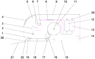
Fig. 1 is a structural view of the present application.
Fig. 2 is a structure diagram of a conveyor belt.
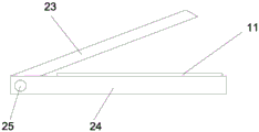
Fig. 3 is a view showing the structure of the cutter.
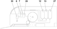
FIG. 4 is a structural view of embodiment 2.
In the figure, 1, a conveyor belt, 2, a water spraying calandria, 3, a three-way valve, 4, a key panel, 5, a PLC, 6, a clean water pump, 7, a makeup removing water pump, 8, an electric heating pipe, 9, a top cover, 10, a towel rolling shaft, 11, a non-woven towel, 12, a clean water bottle, 13, a makeup removing water bottle, 14, a power supply, 15, a negative pressure fan, 16, a towel pressing wheel, 17, a first conveyor belt shaft, 18, an adsorption air pipe, 19, a second conveyor belt shaft, 20, a cutter, 21, a towel supporting plate, 22, an adsorption air hole, 23, a movable knife, 24, a fixed knife, 25, an electric shaft, 26, an alcohol pump, 27, an alcohol bottle, 28, a towel outlet, 29, a liquid supplementing port, 30 and a four-way valve.
Detailed Description
The present invention will be further explained with reference to the drawings and examples.
Example 1
As shown in fig. 1-3, a multifunctional wet towel machine comprises a machine shell and a machine frame, wherein the machine frame is connected with a machine shell at one side, and a side cover of the machine shell is detachable with a top cover 9. The front panel of the casing is provided with a key panel 4, and the key panel 4 is connected with a PLC5 arranged inside the casing. A towel outlet 28 is arranged at the lower corner of the front part of the machine shell, and a towel supporting plate 21 extending out and inclining downwards is arranged at the towel outlet 28 and is used for discharging towels and is convenient to take.
The towel rolling shaft 10 is arranged in the middle of the inside of the machine shell, the two ends of the towel rolling shaft 10 are detachably arranged on the machine frame, the towel rolling shaft 10 can rotate, the center of the non-woven cloth 11 is inserted into the towel rolling shaft 10, and the towel rolling can be installed. A first conveying belt shaft 17 is arranged right below the diameter of a non-woven cloth towel 11, a second conveying belt shaft 19 is arranged at a position close to a towel outlet 28, the horizontal heights of the two conveying belt shafts are the same, a conveying belt 1 is sleeved on the two conveying belt shafts, and the conveying belt shafts are connected with a motor to form a conveying mechanism. A towel pressing wheel 16 is arranged above the first conveyor belt shaft 17 in a tangent position, and the towel pressing wheel 16 is also connected with a motor and can rotate in the opposite direction at the same angular speed as the first conveyor belt shaft 17. After the non-woven cloth towel 11 is installed, one end of the non-woven cloth towel 11 extends into a gap between the towel pressing wheel 16 and the first conveying belt shaft 17, normal use can be achieved, the first conveying belt shaft 17 and the towel pressing wheel 16 rotate synchronously, and the non-woven cloth towel 11 is conveyed forwards to the surface of the conveying belt to be conveyed.
Between first conveyer belt axle 17 and second conveyer belt axle 19, transversely install and adsorb tuber pipe 18, adsorb 18 length of tuber pipe slightly less than the distance between two conveyer belt axles, adsorb tuber pipe 18 and adopt wind-force to adsorb, adsorb the conveyer belt 1 directly over the orientation, adsorb the form that tuber pipe 18 can form the absorption matrix in order to arrange side by side, also can directly select for use the rectangle to adsorb the tuber pipe to the upper surface that the adsorption area can cover conveyer belt 1 basically is accurate. The air port of the adsorption air pipe 18 is connected with the negative pressure fan 15 to provide adsorption force, the negative pressure fan 15 is installed at the bottom of the casing, and the casing below the air pressure fan 15 is provided with a corresponding air port. The conveyor belt 1 is provided with adsorption air holes 22 arranged in a matrix for passing through adsorption air flow.
The clean water bottle 12 and the makeup removing bottle 13 are arranged at the rear part of the inner cavity in parallel, the clean water bottle 12 is used for filling clean water, the makeup removing bottle 13 is used for filling makeup removing water, the clean water bottle 12 and the makeup removing bottle 13 are identical in structure, the top part is a liquid supplementing opening 29 and is tightly covered through a screw cap, the bottom part is funnel-shaped, and the lowest point of the funnel is a liquid outlet. The liquid outlet of the clear water bottle 12 is connected with a clear water pipe and is connected to the electric heating pipe 8 arranged at the front part of the embedded part, the clear water pipe is connected to the clear water pump 6 after passing through the electric heating pipe 8, and the electric heating pipe 8 is of an adjustable temperature control type; the liquid outlet of the makeup removing water bottle 12 is directly connected to the makeup removing water pump 7 through a makeup removing water pipe.
Above conveyer belt 1, installation water spray calandria 2, the mounted position is being close to the central point between two transmission shafts and is putting, and water spray calandria 2 length is the same with conveyer belt 1 width, and the perpendicular downward conveyer belt 1 that faces of water spray direction is apart from making the non-woven fabrics piece of cloth 11 that the water smoke can evenly spray on the conveyer belt. The water inlet of the water spray calandria 2 is controlled by an electromagnetic valve, the electromagnetic valve is connected to the outlet of the three-way valve 3 above through a water pipe, and two inlets of the three-way valve 3 are respectively connected with a clean water pump 6 and a makeup removing water pump 7.
The cutting knife 20 is arranged at the towel outlet 28, the cutting knife 20 is composed of a fixed knife 24 and a movable knife 23 which are fixedly arranged on one side of the second conveying belt shaft, one end of the fixed knife 24 is connected with one end of the movable knife 23 through an electric shaft 25, and the electric shaft 25 rotates under the control of a matched motor to drive the movable knife 23 to be jointed with the fixed knife 24 for shearing. When the cutter 20 is not in working state, the non-woven cloth towel 11 is conveyed to the second conveying belt shaft 19 after the conveying belt is conveyed, passes through the space between the fixed cutter 24 and the movable cutter 23, and is output from the towel outlet 28, and after the cutter is in working state, the output part can be cut off and taken.
The components of the motor of the conveying belt shaft and the towel pressing wheel 16, the clean water pump 6, the makeup removing water pump 7, the electromagnetic valve of the water spray discharge pipe 2, the electric heating pipe 8, the negative pressure fan 15, the cutter 20 and the like are controlled by the PLC5, after the PLC5 is correspondingly programmed, the button panel 4 is used for selecting programs, and the connection mode is line connection. For example, a wet tissue key is selected through the key panel 4, the temperature of the wet tissue is selected through the temperature key, the clean water pump 6 and the electric heating pipe 8 are started, the clean water pump 6 is connected to the water spray calandria 2, and meanwhile, the electric heating pipe 8 heats the clean water flowing through at the selected temperature; meanwhile, the conveying belt shaft and the towel pressing wheel 16 start to rotate, the non-woven cloth towel 11 is conveyed to the towel outlet 28, and the negative pressure fan 15 works synchronously during conveying to perform adsorption. The water spraying calandria 2 is opened to spray clear water to the rolled towel in conveying, and the clear water is uniformly sprayed along with the movement of the rolled towel. After the rolled wet tissues are conveyed out of the tissue outlet 28 for a specified distance, the conveying and spraying are stopped, the cutting key is pressed to start the cutter 20, and the manufactured wet tissues are cut off and can be taken for use. Similarly, when the makeup removing water wet tissue is needed to be used, the keys correspond to the key control program, and the makeup removing water pump 7 is started to pump the makeup removing water. When the towel is required to be rolled separately, the towel rolling key is pressed, so that conveying and cutting can be started under the condition that spraying is not started, and the rolled towel is output separately.
The power supply 14 is arranged at the rear side of the inner cavity, and is connected to the above components needing electric energy by using lines for supplying power, and the power supply 14 is connected with the household circuit through an external cable. The top cover 9 and the side cover are detachable covers, and the non-woven cloth towel 11 can be replaced and the clean water bottle 6 and the makeup removing water bottle 7 can be supplemented with corresponding solutions after being detached.
The above components are all mounted on the rack without description, and the housing and the rack structure are designed according to the required layout of each component and are not specifically limited.
Example 2
As shown in fig. 4, the specific structure of this embodiment is the same as that of embodiment 1, except that:
the clean water bottle 12, the makeup removing bottle 13 and the alcohol bottle 27 are arranged at the rear part of the inner cavity in parallel, the clean water bottle 12 is used for filling clean water, the makeup removing bottle 13 is used for filling makeup removing water, the alcohol bottle 27 is used for filling medical alcohol, the clean water bottle 12, the makeup removing bottle 13 and the alcohol bottle 27 are identical in structure, the top is a liquid supplementing opening 29 and is tightly covered through a screw cap, the bottom is funnel-shaped, and the lowest point of the funnel is a liquid outlet. The liquid outlet of the clear water bottle 12 is connected with a clear water pipe and is connected to the electric heating pipe 8 arranged at the front part of the embedded part, the clear water pipe is connected to the clear water pump 6 after passing through the electric heating pipe, and the electric heating pipe 8 is of an adjustable temperature control type; the liquid outlet of the makeup removing water bottle 13 is directly connected to the makeup removing water pump 7 through a makeup removing water pipe; the outlet of the spirit bottle 27 is connected directly to the spirit pump 26 via an alcohol pipe. It should be noted that, when wiring each pipeline, the alcohol pipe needs to be far away from the electric heating pipe 8, and can be wound around the bottom of the inner cavity or be wired with a larger distance, so as to prevent accidents.
The valve connected with the electromagnetic valve of the water spray calandria 2 is a four-way valve 30, and three inlets of the four-way valve 30 are respectively connected with the clean water pump 6, the makeup removing water pump 7 and the alcohol pump 26. The key panel 4 and the PLC5 are provided with a program for controlling the alcohol pump and a key control logic.
The remaining mechanical mechanisms were the same as in example 1.
Claims (10)
1. A multifunctional wet towel machine comprises a machine shell and a machine frame, wherein the machine shell covers the machine frame to form an inner cavity, one end of the machine shell is provided with a towel outlet, a conveying mechanism, a spraying mechanism and a towel rolling mechanism are arranged in the inner cavity, the towel rolling mechanism is connected with the conveying mechanism, and the spraying mechanism is connected with the conveying mechanism;
conveying mechanism includes two parallel conveying belt shafts and conveyer belt, and one of them conveying belt shaft is close to out the piece of cloth mouth, the conveyer belt cover is established at two conveying belt shafts, keeps away from and still is equipped with the pressure piece of cloth wheel between conveying belt shaft and the roll piece of cloth mechanism of a towel mouth one side.
2. The multifunctional wet towel machine as claimed in claim 1, wherein the solution bottles comprise two clean water bottles and two makeup removing bottles, the valve bodies are three-way valves, the clean water bottles and the makeup removing bottles are respectively connected to the inlets of the three-way valves through corresponding electric pumps, and the outlets of the three-way valves are connected with the spray pipes.
3. The multifunctional wet towel machine as claimed in claim 1, wherein the solution bottles comprise a clean water bottle, a makeup removing bottle and an alcohol bottle, the number of the electric pumps is three, the valve bodies are four-way valves, the clean water bottle, the makeup removing bottle and the alcohol bottle are respectively connected to the inlet of the four-way valve through corresponding electric pumps, and the outlet of the four-way valve is connected with a spray pipe.
4. The multifunctional wet towel machine as claimed in claim 2 or 3, wherein an electric heating pipe is arranged between the clean water bottle and the corresponding electric pump.
5. The multifunctional wet towel machine as claimed in any one of claims 1-3, wherein the solution bottle is provided with a solution replenishing port;
the bottom of the solution bottle is provided with a funnel-shaped liquid outlet which is connected with a corresponding electric pump.
6. The multifunctional wet towel machine according to claim 1, wherein the conveying mechanism further comprises an adsorption component, the adsorption component comprises an adsorption air pipe and a negative pressure fan, the adsorption air pipe is arranged between the two conveying belt shafts, the adsorption air pipe is arranged between the conveying belts, the adsorption air pipe is connected with the negative pressure fan, and the negative pressure fan is arranged in the inner cavity;
and the conveying belt is provided with an adsorption air hole.
7. The multi-functional wet towel dispenser according to claim 6, wherein the suction direction of the suction air duct is toward the upper conveyor belt, and the suction air flow moves from top to bottom.
8. The multifunctional wet towel machine according to claim 1, further comprising a cutter mechanism, wherein the cutter mechanism is arranged at one end of the conveying mechanism far away from the towel rolling mechanism;
the cutter mechanism comprises a fixed cutter and a movable cutter, and one end of the fixed cutter is movably connected with one end of the movable cutter through an electric shaft.
9. The multifunctional wet towel machine according to claim 1, further comprising a control mechanism, wherein the control mechanism comprises a key panel and a PLC, the key panel is arranged outside the housing, the PLC is arranged in the inner cavity, and the key panel is connected with the PLC;
the conveying mechanism, the spraying mechanism and the towel rolling mechanism are all connected with the PLC;
the towel rolling machine further comprises a power supply, and the PLC, the conveying mechanism, the spraying mechanism and the towel rolling mechanism are all connected with the power supply.
10. The multifunctional wet towel machine as claimed in claim 1, wherein the towel rolling mechanism comprises a towel rolling shaft and a towel rolling mechanism, the towel rolling shaft is connected with the central shaft of the towel rolling shaft, and the towel rolling shaft is connected with the conveying mechanism through a towel pressing wheel;
the length of the spray pipe is matched with the width of the rolled towel.
Priority Applications (1)
| Application Number | Priority Date | Filing Date | Title |
|---|---|---|---|
| CN202121163179.4U CN215077929U (en) | 2021-05-27 | 2021-05-27 | Multifunctional wet tissue machine |
Applications Claiming Priority (1)
| Application Number | Priority Date | Filing Date | Title |
|---|---|---|---|
| CN202121163179.4U CN215077929U (en) | 2021-05-27 | 2021-05-27 | Multifunctional wet tissue machine |
Publications (1)
| Publication Number | Publication Date |
|---|---|
| CN215077929U true CN215077929U (en) | 2021-12-10 |
Family
ID=79300067
Family Applications (1)
| Application Number | Title | Priority Date | Filing Date |
|---|---|---|---|
| CN202121163179.4U Active CN215077929U (en) | 2021-05-27 | 2021-05-27 | Multifunctional wet tissue machine |
Country Status (1)
| Country | Link |
|---|---|
| CN (1) | CN215077929U (en) |
-
2021
- 2021-05-27 CN CN202121163179.4U patent/CN215077929U/en active Active
Similar Documents
| Publication | Publication Date | Title |
|---|---|---|
| CN107761309A (en) | A kind of washing machine that function is washed with steam | |
| CN111041755B (en) | Cloth ironing device with double-sided anti-wrinkling function | |
| CN207031461U (en) | A kind of multifunctional leather embossing machine | |
| CN217465265U (en) | Drying device for dyeing polyester fabric | |
| CN215077929U (en) | Multifunctional wet tissue machine | |
| CN206815041U (en) | A kind of multiple laundry cleaning device | |
| CN207227833U (en) | A kind of clothing expands Scissoring device with cloth | |
| CN212128558U (en) | Cloth ironing device is used in dress production | |
| CN212895467U (en) | Heat setting machine for producing crease-resistant cloth | |
| CN215561268U (en) | Dyed cloth ironing device | |
| CN217154847U (en) | Drying equipment for textile yarns | |
| CN213951611U (en) | Humidification device is used in cotton soft piece of cloth production and processing | |
| CN114507958A (en) | A high-efficient dyeing and finishing equipment for chamois leather matte material production and processing | |
| CN213013415U (en) | Gauze flattening device is used in gauze production | |
| CN212335515U (en) | Automatic feeding device for wet tissue production | |
| CN112111875A (en) | Cloth humidifying device of textile machinery for cloth production | |
| CN216427698U (en) | Grey cloth surface wrinkle removing equipment | |
| CN216919682U (en) | Textile cloth wetting device for spinning | |
| CN216502187U (en) | Twelve-tooth punching rod processing mold multiple cooling device | |
| CN216551060U (en) | Humidifying equipment for synthetic leather processing | |
| CN215412750U (en) | Quick cooler of bean vermicelli processing usefulness | |
| CN220034952U (en) | Garment processing ironing equipment | |
| CN220326963U (en) | Multicolor sole casual shoes and processing equipment thereof | |
| CN213830936U (en) | Energy-concerving and environment-protective high-speed intelligent printing machine | |
| CN114990837B (en) | Local cleaning device |
Legal Events
| Date | Code | Title | Description |
|---|---|---|---|
| GR01 | Patent grant | ||
| GR01 | Patent grant |