CN215076743U - Combined express cabinet - Google Patents
Combined express cabinet Download PDFInfo
- Publication number
- CN215076743U CN215076743U CN202120751194.4U CN202120751194U CN215076743U CN 215076743 U CN215076743 U CN 215076743U CN 202120751194 U CN202120751194 U CN 202120751194U CN 215076743 U CN215076743 U CN 215076743U
- Authority
- CN
- China
- Prior art keywords
- connecting piece
- cabinet
- door lock
- box
- modular
- Prior art date
- Legal status (The legal status is an assumption and is not a legal conclusion. Google has not performed a legal analysis and makes no representation as to the accuracy of the status listed.)
- Active
Links
Images


Landscapes
- Casings For Electric Apparatus (AREA)
Abstract
The utility model discloses a modular express delivery cabinet, including top cabinet, box and base the top of box is equipped with first connecting piece the below of box is equipped with the second connecting piece, the box passes through first connecting piece with the connection can be dismantled to the second connecting piece. A third connecting piece is arranged below the top cabinet, and the third connecting piece is matched with the first connecting piece to realize detachable connection; the top of base is equipped with the fourth connecting piece, the fourth connecting piece with the second connecting piece adaptation is realized dismantling the connection. The utility model discloses a simple structure has realized simple and easy installation and the dismantlement of express delivery cabinet, and the weight of every part is limited, conveniently transports respectively and installs behind the predetermined site, and easy to assemble simultaneously is accomplished the maintenance and is retrieved, is favorable to popularizing and using.
Description
Technical Field
The utility model relates to an express delivery cabinet field especially relates to a modular express delivery cabinet.
Background
In modern life, express cabinets are the user's choice when not convenient to receive express. However, the existing express cabinet often needs a large space for storage, and the express cabinet is heavy as a whole, so that the express cabinet is difficult to transport before installation and difficult to maintain, replace or disassemble and recover after installation, thereby often limiting the application scene of the express cabinet and causing difficulty in popularizing and installing the express cabinet in an area with a small space or a small budget.
Accordingly, the prior art is yet to be improved and developed.
SUMMERY OF THE UTILITY MODEL
In view of the above-mentioned prior art not enough, the utility model aims at providing a modular express delivery cabinet aims at solving current modular express delivery cabinet occupation space big, weight is heavy, thereby the transportation difficulty just is difficult to the installation and dismantles the problem that influences the popular express delivery cabinet of using.
The technical scheme of the utility model as follows:
a modular express delivery cabinet, wherein, includes:
the box body is provided with a first connecting piece above, a second connecting piece below, and the box bodies are detachably connected through the first connecting piece and the second connecting piece in a matched mode;
the third connecting piece is matched with the first connecting piece to realize detachable connection;
the base, the base top is equipped with the fourth connecting piece, the fourth connecting piece with the second connecting piece adaptation is realized dismantling the connection.
Combination formula express delivery cabinet, wherein, first connecting piece includes:
the sliding buckle groove is fixed above the box body, and two ends of the sliding buckle groove are opened;
the slide fastener is arranged in the slide fastener groove, the first end of the slide fastener extends out of one end of the slide fastener groove and is clamped with the second connecting piece, the second end of the slide fastener extends out of the other end of the slide fastener groove, and the second end is pulled to realize the sliding of the slide fastener in the slide fastener groove.
The combination formula express delivery cabinet, wherein, the second connecting piece includes:
the baffles are arranged in pairs and are vertically fixed below the box body;
the buckle is arranged between the pair of baffles, one end of the buckle is hinged to the baffles, and the other end of the buckle is provided with a bayonet and is clamped with the first connecting piece.
Combination formula express delivery cabinet, wherein, first connecting piece still includes:
the elastic piece is arranged between the sliding buckle groove and the sliding buckle and provides elastic force to ensure that one end of the first end of the sliding buckle, which extends out of the sliding buckle groove, is clamped with the second connecting piece.
The combined express cabinet is characterized in that the third connecting piece and the second connecting piece have the same structure, and the fourth connecting piece and the first connecting piece have the same structure.
Combination formula express delivery cabinet, wherein, the box includes:
the first connecting piece is fixed above the body, and the second connecting piece is fixed below the body;
the box door is hinged with the body to realize the opening and closing of the box body;
the door lock device is arranged on one side of the body and used for realizing the locking connection of the box door and the body.
The combination formula express delivery cabinet, wherein, door lock device includes:
the first door lock assembly is fixed on one side of the body;
the second door lock assembly is fixed on the box door, corresponds to the first door lock assembly when the box door and the body are closed, and realizes the locking connection of the box door and the body;
the emergency door lock assembly is connected with the first door lock assembly, and manual unlocking of the door lock device is achieved when the door lock device breaks down.
The combination formula express delivery cabinet, wherein, the top cabinet includes:
the control device is fixed in the top cabinet, is electrically connected with the door lock device and controls the locking and unlocking of the door lock device;
the power supply device is fixed inside the top cabinet, is electrically connected with the control device and provides energy for the control device and the door lock device;
the top cover is arranged above the top cabinet and is pivoted with the top cabinet, and the control device and the power supply device are sealed in the top cabinet after the top cover is buckled with the top cabinet.
The combination formula express delivery cabinet, wherein, the base below is equipped with the supporting legs, in order to support combination formula express delivery cabinet.
The combined express cabinet is characterized in that one end of each supporting leg is a supporting rod and is abutted to the base, and the other end of each supporting leg is a non-slip mat.
Compared with the prior art, the utility model discloses a modular express delivery cabinet, including top cabinet, box and base the top of box is equipped with first connecting piece the below of box is equipped with the second connecting piece, the box passes through first connecting piece with the connection can be dismantled in the realization of second connecting piece adaptation. A third connecting piece is arranged below the top cabinet, and the third connecting piece is matched with the first connecting piece to realize detachable connection; the top of base is equipped with the fourth connecting piece, the fourth connecting piece with the second connecting piece adaptation is realized dismantling the connection. The utility model discloses a simple structure has realized simple and easy installation and the dismantlement of express delivery cabinet, and the weight of every part is limited, conveniently transports respectively and installs behind the predetermined site, and easy to assemble simultaneously is accomplished the maintenance and is retrieved, is favorable to popularizing and using.
Drawings
Figure 1 is a perspective view of combination formula express delivery cabinet.
Figure 2 is the explosion chart of combination formula express delivery cabinet.
Figure 3 is two boxes of combination formula express delivery cabinet match the sketch map.
Figure 4 is the box of combination formula express delivery cabinet's schematic diagram.
Figure 5 is another angle schematic diagram of box of combination formula express delivery cabinet.
Figure 6 is combination formula express delivery cabinet's first connecting piece and second connecting piece card hold the schematic diagram.
Figure 7 is combination formula express delivery cabinet's first connecting piece cross-sectional view.
Figure 8 is the box elevation view of combination formula express delivery cabinet.
Figure 9 is combination formula express delivery cabinet's locks and chamber door schematic diagram.
Figure 10 is the top cabinet schematic view of combination formula express delivery cabinet.
Figure 11 is another angle schematic diagram of the top cabinet of the combined express delivery cabinet of the present invention.
Figure 12 is the base schematic view of combination formula express delivery cabinet.
Fig. 13 is a front view of another embodiment of the combined express delivery cabinet of the present invention.
Fig. 14 is a schematic view of a door lock device and a door of another embodiment of the combined express delivery cabinet of the present invention.
Detailed Description
The utility model provides a modular express delivery cabinet, for making the utility model discloses a purpose, technical scheme and effect are clearer, more clear and definite, following right the utility model discloses further detailed description. It should be understood that the specific embodiments described herein are merely illustrative of the invention and are not intended to limit the invention.
It should be noted that the terms "center", "upper", "lower", "left", "right", "inner", "outer", "vertical", "horizontal", and the like indicate orientations or positional relationships based on the orientations or positional relationships shown in the drawings, and are only for convenience of description and simplification of description, but do not indicate or imply that the structures referred to must have a specific orientation or must be constructed in a specific orientation, and should not be construed as limiting the present invention.
In addition, the articles "a" and "the" may refer broadly to the singular or plural unless the context specifically states otherwise. If there is a description in an embodiment of the present invention referring to "first", "second", etc., the description of "first", "second", etc. is for descriptive purposes only and is not to be construed as indicating or implying relative importance or implicitly indicating the number of technical features indicated. Thus, a feature defined as "first" or "second" may explicitly or implicitly include at least one such feature. In addition, the technical solutions in the embodiments may be combined with each other, but it must be based on the realization of those skilled in the art, and when the technical solutions are contradictory or cannot be realized, the combination of the technical solutions should not be considered to exist, and is not within the protection scope of the present invention.
As shown in fig. 1, the combined express cabinet of the present invention includes a box body 100, a top cabinet 200 and a base 300. As shown in fig. 2, a first connecting member 110 is disposed above the box body 100, a second connecting member 120 is disposed below the box body 100, and the two box bodies 100 are detachably connected by the first connecting member 110 and the second connecting member 120 in a matching manner, so as to realize combined connection in a vertical direction. A third connecting piece 210 is arranged below the top cabinet 200, and the third connecting piece 210 is adaptive to the first connecting piece 110 and clamped to realize the detachable connection of the top cabinet 200 and the box body 100 in the vertical direction. A fourth connecting member 310 is arranged above the base 300, and the fourth connecting member 310 is adapted to the second connecting member 120 to be clamped, so that the box 100 and the base 300 can be detachably connected in the vertical direction. Through box 100, top cabinet 200 with detachable the connection between the base 300, realization that can be very convenient the installation and the dismantlement of combination formula express delivery cabinet can set up the express delivery cabinet of equidimension not according to the space size of concrete position simultaneously, has expanded the application of express delivery cabinet, does benefit to the popularization.
As shown in fig. 8, the cabinet 100 includes the first link 110, the second link 120, a body 130, a door 140, and a door lock device 150.
As shown in fig. 3 and 5, the first connecting member 110 is fixedly disposed above the body 130, and further, the first connecting member 110 is fixedly disposed inside the upper surface of the body 130, that is, inside the box 100. As shown in fig. 6 and 7, the first connecting member 110 includes a sliding buckle slot 111 and a sliding buckle 112, the sliding buckle slot 111 is fixed on the inner side of the upper surface of the body 130, and has openings at both ends, the sliding buckle 112 is disposed in the sliding buckle slot 111, and a first end 112A and a second end 112B of the sliding buckle 112 respectively protrude from the openings at both ends of the sliding buckle slot 111. As shown in fig. 6, the first end 112A of the slider 112 extends from one end of the slider groove 111 and is engaged with the second connector 120. Further, a through hole 160 is formed in a portion of the upper surface of the body 130, which extends out of the sliding buckle slot 111 corresponding to the first end 112A, so that the second connecting member 120 is inserted from above and is clamped with the first end 112A of the sliding buckle 112, thereby realizing clamping connection between the second connecting member 120 and the first connecting member 110. Further, the first end 112A is configured in a bolt shape, and a side opposite to the second connector 120 is configured with an inclined surface, such that when the second connector 120 is inserted from the through hole 160 in a vertical direction relative to the first connector 110, the slider 112 is retracted into the slider groove 111 under an interaction force between the second connector 120 and the first end 112A of the slider 112, and after the second connector 120 reaches the retaining position, the first end 112A protrudes from the slider groove 111 again by pushing and pulling the slider 112, so as to achieve the adaptive retaining of the first connector 110 and the second connector 120. As shown in fig. 7, the second end 112B of the slider 112 extends from the other end of the slider groove 111, and a user can push and pull the slider 112 by grasping the second end 112B with a hand to slide the slider 112 in the slider groove 111, so as to achieve the expansion and contraction of the first end 112A relative to the slider groove 111 to assist in completing the engagement and disengagement of the first connector 110 and the second connector 120. Optionally, the second end 112B of the slider 112 is in the shape of a handle, which is convenient for a user to grasp; optionally, the second end 112B is provided with a hollow hole, so that a user can conveniently hook the drawing with fingers. Further, the first connecting member 110 further includes an elastic member 113, and the elastic member 113 is disposed between the sliding buckle 112 and the sliding buckle slot 111, and provides an elastic force to ensure that the first end 112A of the sliding buckle 112 extends out of the sliding buckle slot 111, so that the first connecting member 110 and the second connecting member 120 can be clamped and connected without manual operation of a user. The detachable connection between the box bodies 100 can be realized through a simple structure, and the box body is simple and practical.
As shown in fig. 3 and 5, the second connector 120 is fixedly disposed below the body 130, and further, the second connector 120 is fixedly disposed outside a lower surface of the body 130. The second connector 120 includes a baffle 121 and a buckle 122, as shown in fig. 5 and 6, the baffle 121 is arranged in pairs and fixed to the outer side of the lower surface of the body 130 perpendicularly to the lower surface of the body 130; the snaps 122 are disposed between the pair of the shutters 121. One end of the buckle 122 is hinged with the baffle plates 121, so that the buckle 122 can rotate between the baffle plates 121; the other end of the buckle 122 is provided with a bayonet 123, and the bayonet 123 is matched with the slide fastener 112 in the first connecting piece 110 for clamping. When the clamping is not needed, the buckle 122 is rotated to be parallel to the lower surface of the body 130, and the box 100 can be directly placed on a horizontal plane. When the second connector 120 and the first connector 110 need to be clamped, the buckle 122 rotates to be perpendicular to the lower surface of the body 130 under the action of gravity, and the buckle 122 is inserted into the first connector 110 from the through hole 160 downwards in the vertical direction, so that the bayonet 123 and the slider 112 are clamped, and the clamping connection between the second connector 120 and the first connector 110 is realized. The detachable connection between the box bodies 100 can be realized through a simple structure, and the box body is simple and practical.
As shown in fig. 4 and 5, the door 140 is hinged to the body 130 to open and close the cabinet 100. Optionally, a plurality of parallel doors 140, for example 2, 3 or 5, are hinged on one body 130, and the specific number may be changed according to the requirement. As shown in fig. 8 and 9, the door lock device 150 is fixed to one side of the body 130, and when the door 140 is closed with the body 130, the door lock device 150 cooperates with the door 140 to lock the door 140 with the body 130, so as to lock the cabinet 100. Further, the door lock device 150 includes a first door lock assembly 151, a second door lock assembly 152 and an emergency door lock device 153, the first door lock assembly 151 is fixed to one side of the body 130, and the second door lock assembly 152 is fixed to the door 140 and is disposed at a position corresponding to the first door lock assembly 151. When the door 140 is closed with the body 130, the first door lock assembly 151 is in locking connection with the second door lock assembly 152 to lock the door 140 with the body 130. As shown in fig. 4 and 8, the emergency door lock assembly 153 is disposed in the body 130 and located on the same side as the first door lock assembly 151, and the emergency door lock assembly 153 is connected to the first door lock assembly 151 and manually unlocks the first door lock assembly 151 through the emergency door lock assembly 153. In an embodiment of the present invention, the emergency door lock assembly 153 is extended from the top of the box 100, and the emergency door lock assembly 153 is connected to the first door lock assembly 151, when the door lock device 150 fails and cannot be normally opened, the emergency door lock assembly 153 is manually lifted and pulled to be synchronized with the first door lock assembly 151, so as to unlock the door lock device 150. In another embodiment of the present invention, the emergency door lock assembly 153 is enclosed in the body 130, i.e. enclosed inside the box 100, as shown in fig. 13 and 14, the emergency door lock assembly 153 includes a lock head 153A and a connecting rod 153B, the lock head 153A is fixed inside the upper side wall of the body 130, and the connecting rod 153B is perpendicular to the lock head 153A and disposed below the lock head 153A. One end of the connection rod 153B is connected to the locking head 153A, and the other end of the connection rod 153B extends downward to connect the connection rod 153B to all the first door lock assemblies 151. When the door lock device 150 fails and cannot be normally opened, the lock 153A is turned by a key, the lock 153A converts rotary motion into linear motion, and the linear motion is used for replacing manual lifting to drive the connecting rod 153B to linearly move in the vertical direction so as to synchronously control all the first door lock assemblies 151 to be unlocked, so that the door lock device 150 is opened, and the emergency door lock assemblies 153 are sealed in the box body 100, so that the situation that the box body 100 is overlapped due to the protrusion of the emergency door lock assemblies 153 is avoided, and the express cabinet is more simple and convenient to assemble and disassemble. Optionally, when a plurality of doors 140 are hinged to one of the bodies 130, the door lock device 150 includes a plurality of first door lock assemblies 151 and corresponding second door lock assemblies 152 to lock and unlock a plurality of doors 140 and the body 130.
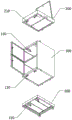
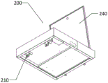
As shown in fig. 10 and 11, the top cabinet 200 includes a top cover 240, a power supply unit 220, and a control unit 230, in addition to the third connecting member 210 disposed under the top cabinet 200. The third connecting member 210 and the second connecting member 120 have the same structure, and the third connecting member 210 is fixed below the top cabinet 200, so that the top cabinet 200 and the body 130 can be detachably connected by clamping the third connecting member 210 and the first connecting member 110. The power supply unit 220 and the control unit 230 are fixed in the top cabinet 200, the top cover 240 is hinged to the top cabinet 200, and the top cover 240 closes the top cabinet 200 to enclose the power supply unit 220 and the control unit 230 in the top cabinet 200. Further, the control device 230 is a control circuit board, and is electrically connected to the power supply device 220 and the door lock device 150 in the express delivery cabinet 100, respectively. The control device 230 controls the locking and unlocking of the door lock device 150, thereby controlling the locking and unlocking of the door 140 and the body 130, and thus achieving the opening and closing of the cabinet 100. The power supply unit 220 supplies power to the control unit 230 and the door lock unit 150. Further, the power supply device 220 is a rechargeable battery. Further, a top cabinet opening 250 is formed in the position, corresponding to the emergency door lock assembly 153, of the door lock device 150 of the top cabinet 200, and the emergency door lock assembly 153 extends into the top cabinet 200 through the top cabinet opening 250, so that the emergency door lock device 153 can be used for manually unlocking the door lock device 150 only by opening the top cover 240 without detaching the top cabinet 200 from the box body 100.
As shown in fig. 12, the fourth connecting member 310 disposed on the base 300 has the same structure as the first connecting member 120, and the fourth connecting member 310 is fixed above the base 300, so that the detachable connection between the body 130 and the base 300 is realized by the clamping of the fourth connecting member 310 and the second connecting member 120.
As shown in fig. 12, the base 300 further includes a supporting leg 320 vertically disposed below the base 300, in addition to the fourth connecting member 310 disposed above the base 300, and the supporting leg 320 is used for supporting the combination express delivery cabinet. Further, there are 4 supporting legs 320 symmetrically disposed to support the base 300, so as to support the combined express delivery cabinet more stably. Optionally, one end of the supporting leg 320 is a supporting bar abutted to the base 300, and the other end of the supporting leg 320 is a non-slip mat. Optionally, one end of the supporting leg 320 is a supporting bar and is abutted to the base 300, and the other end of the supporting leg 320 is provided with a universal wheel so as to facilitate the movement of the combined express cabinet after the installation.
Modular express delivery cabinet just can realize through simple structure top cabinet 200 box 100 with can dismantle between the base 300 and connect. It should be noted that the number of the boxes 100 can be increased or decreased according to specific needs, for example, 3 boxes 100 can be detachably connected and placed between the top cabinet 200 and the base 300 according to the size of the space. Can transport each part to the predetermined place respectively like this before the installation, because the weight of single part is limited, the transportation degree of difficulty greatly reduced, and assemble the box of different quantity as required in the predetermined place, can effectively deal with the needs under the multiple scene, conveniently popularize and use the express delivery cabinet.
The utility model discloses a modular express delivery cabinet, including top cabinet, box and base the top of box is equipped with first connecting piece the below of box is equipped with the second connecting piece, the box passes through first connecting piece with the connection is held to the second connecting piece card. A third connecting piece is arranged below the top cabinet and is clamped with the first connecting piece in a matched manner; and a fourth connecting piece is arranged above the base and is matched with the second connecting piece in a clamping manner. The utility model discloses a simple structure has realized simple and easy installation and the dismantlement of express delivery cabinet, and the weight of every part is limited, conveniently transports respectively and installs behind the predetermined site, and easy to assemble simultaneously is accomplished the maintenance and is retrieved, is favorable to popularizing and using.
It should be understood that the above description of the preferred embodiments of the present invention is intended to be specific and not to be construed as limiting the scope of the invention, which is defined by the appended claims.
Claims (10)
1. A modular express delivery cabinet, its characterized in that includes:
the box body is provided with a first connecting piece above, a second connecting piece below, and the box bodies are detachably connected through the first connecting piece and the second connecting piece in a matched mode;
the third connecting piece is matched with the first connecting piece to realize detachable connection;
the base, the base top is equipped with the fourth connecting piece, the fourth connecting piece with the second connecting piece adaptation is realized dismantling the connection.
2. The modular courier cabinet of claim 1, wherein the first connector comprises:
the sliding buckle groove is fixed above the box body, and two ends of the sliding buckle groove are opened;
the slide fastener is arranged in the slide fastener groove, the first end of the slide fastener extends out of one end of the slide fastener groove and is clamped with the second connecting piece, the second end of the slide fastener extends out of the other end of the slide fastener groove, and the second end is pulled to realize the sliding of the slide fastener in the slide fastener groove.
3. The modular courier cabinet of claim 2, wherein the second connector comprises:
the baffles are arranged in pairs and are vertically fixed below the box body;
the buckle is arranged between the pair of baffles, one end of the buckle is hinged to the baffles, and the other end of the buckle is provided with a bayonet and is clamped with the first connecting piece.
4. The modular courier cabinet of claim 3, wherein the first connector further comprises:
the elastic piece is arranged between the sliding buckle groove and the sliding buckle and provides elastic force to ensure that one end of the first end of the sliding buckle, which extends out of the sliding buckle groove, is clamped with the second connecting piece.
5. The modular courier cabinet of claim 3, wherein the third connector is of the same configuration as the second connector and the fourth connector is of the same configuration as the first connector.
6. The modular courier cabinet of claim 1, wherein the cabinet comprises:
the first connecting piece is fixed above the body, and the second connecting piece is fixed below the body;
the box door is hinged with the body to realize the opening and closing of the box body;
the door lock device is arranged on one side of the body and used for realizing the locking connection of the box door and the body.
7. The modular courier cabinet of claim 6, wherein the door lock mechanism comprises:
the first door lock assembly is fixed on one side of the body;
the second door lock assembly is fixed on the box door, corresponds to the first door lock assembly when the box door and the body are closed, and realizes the locking connection of the box door and the body;
the emergency door lock assembly is connected with the first door lock assembly, and manual unlocking of the door lock device is achieved when the door lock device breaks down.
8. The modular courier cabinet of claim 6, wherein the top cabinet comprises:
the control device is fixed in the top cabinet, is electrically connected with the door lock device and controls the locking and unlocking of the door lock device;
the power supply device is fixed inside the top cabinet, is electrically connected with the control device and provides energy for the control device and the door lock device;
the top cover is hinged to the top cabinet, and the control device and the power supply device are sealed in the top cabinet after the top cover is buckled with the top cabinet.
9. The modular cabinet as recited in claim 1, wherein support legs are provided below the base for supporting the modular cabinet.
10. The modular express delivery cabinet of claim 9, wherein one end of the support foot is a support bar that abuts the base, and the other end of the support foot is a non-slip mat.
Priority Applications (1)
| Application Number | Priority Date | Filing Date | Title |
|---|---|---|---|
| CN202120751194.4U CN215076743U (en) | 2021-04-12 | 2021-04-12 | Combined express cabinet |
Applications Claiming Priority (1)
| Application Number | Priority Date | Filing Date | Title |
|---|---|---|---|
| CN202120751194.4U CN215076743U (en) | 2021-04-12 | 2021-04-12 | Combined express cabinet |
Publications (1)
| Publication Number | Publication Date |
|---|---|
| CN215076743U true CN215076743U (en) | 2021-12-10 |
Family
ID=79265500
Family Applications (1)
| Application Number | Title | Priority Date | Filing Date |
|---|---|---|---|
| CN202120751194.4U Active CN215076743U (en) | 2021-04-12 | 2021-04-12 | Combined express cabinet |
Country Status (1)
| Country | Link |
|---|---|
| CN (1) | CN215076743U (en) |
-
2021
- 2021-04-12 CN CN202120751194.4U patent/CN215076743U/en active Active
Similar Documents
| Publication | Publication Date | Title |
|---|---|---|
| KR101263446B1 (en) | Mortise door lock | |
| CN112932109A (en) | Combined express cabinet and assembling method thereof | |
| CN215076743U (en) | Combined express cabinet | |
| CN101289054B (en) | Twin-lock quick-release locking mechanism | |
| CN203852078U (en) | Multi-purpose horizontal cabinet with integrated bed and bureau | |
| CN215076741U (en) | Unit express delivery cabinet | |
| JP2020032181A (en) | Distribution terminal and article access device | |
| CN211632315U (en) | Data cabinet with remote control | |
| CN209182934U (en) | A kind of books locking device | |
| CN208089045U (en) | A kind of luggage security locking device | |
| CN113273825A (en) | Express cabinet combination setting method and express cabinet | |
| CN214176480U (en) | Switch board convenient to maintenance personal overhauls operation | |
| KR102453445B1 (en) | Door lock | |
| CN216118695U (en) | Hide folding from bullet type keyboard storehouse structure | |
| CN215732030U (en) | Battery fixing device for preventing battery of electric vehicle from being stolen | |
| CN211765052U (en) | Battery replacing structure and outdoor robot | |
| CN219355192U (en) | Folding strength training machine | |
| CN217707230U (en) | Container handle convenient to it is folding fixed | |
| CN217151593U (en) | Electric control lock emergency device and storage cabinet | |
| CN216529197U (en) | Make things convenient for outdoor energy storage battery cabinet of single-door that opens and shuts | |
| CN213785854U (en) | Hold box and install above-mentioned draw-bar box that holds box | |
| CN218029738U (en) | Drawer structure of base for safety cabinet | |
| CN215108322U (en) | Safety door capable of being rapidly disassembled and assembled | |
| CN213876545U (en) | Novel portable industrial computer | |
| CN218922088U (en) | Anti-lost intelligent household storage cabinet model |
Legal Events
| Date | Code | Title | Description |
|---|---|---|---|
| GR01 | Patent grant | ||
| GR01 | Patent grant |